belt NISSAN LATIO 2009 Service Repair Manual
[x] Cancel search | Manufacturer: NISSAN, Model Year: 2009, Model line: LATIO, Model: NISSAN LATIO 2009Pages: 4331, PDF Size: 58.04 MB
Page 3760 of 4331
ENGINE MAINTENANCE (HR16DE)
MA-17
< SERVICE INFORMATION >
C
D E
F
G H
I
J
K
M A
B MA
N
O P
• When the lock nut is loosened excessively, the idle
r pulley tilts and the correct tension adjust-
ment cannot be performed. Never loo sen it excessively (more than 45 degrees).
• Put a matching mark on the lock nut, and check turning angle with a protractor. Never visually
check the tightening angle.
2. Adjust the belt tension by turning the adjusting bolt. CAUTION:
• When checking immediately after in stallation, first adjust it to the specified value. Then, after
turning crankshaft two turns or more, re-adjust to the specified value to avoid variation in deflec-
tion between pulleys.
• When the tension adjustment is performed, the lo ck nut should be in the condition at step“2”. If
the tension adjustment is performed when the lo ck nut is loosened more than the standard, the
idler pulley tilts and the correct tens ion adjustment cannot be performed.
3. Tighten the idler pulley lock nut.
ENGINE COOLANT
ENGINE COOLANT : Inspection INFOID:0000000004806014
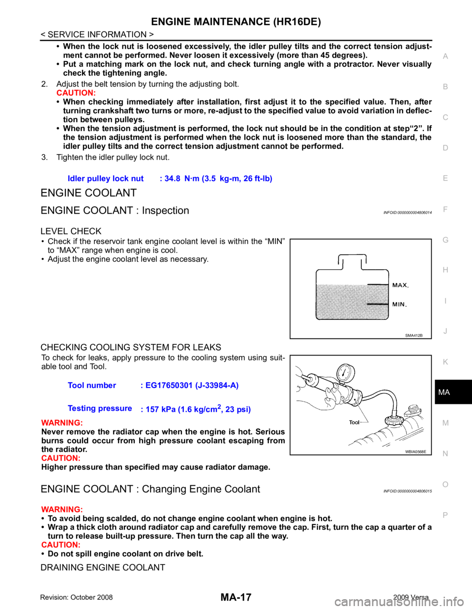
LEVEL CHECK • Check if the reservoir tank engine coolant level is within the “MIN” to “MAX” range when engine is cool.
• Adjust the engine coolant level as necessary.
CHECKING COOLING SYSTEM FOR LEAKS To check for leaks, apply pressure to the cooling system using suit-
able tool and Tool.
WARNING:
Never remove the radiator cap wh en the engine is hot. Serious
burns could occur from high pressure coolant escaping from
the radiator.
CAUTION:
Higher pressure than specified may cause radiator damage.
ENGINE COOLANT : Chang ing Engine Coolant INFOID:0000000004806015
WARNING:
• To avoid being scalded, do not change engine coolant when engine is hot.
• Wrap a thick cloth around radiator cap and carefully remove the cap. First, turn the cap a quarter of a
turn to release built-up pressure. Then turn the cap all the way.
CAUTION:
• Do not spill engine coolant on drive belt.
DRAINING ENGINE COOLANT Idler pulley lock nut : 34.8 N·m (3.5 kg-m, 26 ft-lb)
SMA412B
Tool number : EG17650301 (J-33984-A)
Testing pressure : 157 kPa (1.6 kg/cm 2
, 23 psi) WBIA0568E
Page 3761 of 4331
MA-18< SERVICE INFORMATION >
ENGINE MAINTENANCE (HR16DE)
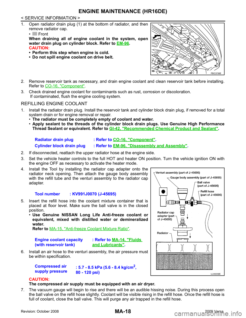
1. Open radiator drain plug (1) at the bottom of radiator, and then remove radiator cap.
• Front
When draining all of engine coolant in the system, open
water drain plug on cylinder block. Refer to EM-96 .
CAUTION:
• Perform this step when engine is cold.
• Do not spill engine coolant on drive belt.
2. Remove reservoir tank as necessary, and drain engine coolant and clean reservoir tank before installing. Refer to CO-16, " Component " .
3. Check drained engine coolant for contaminants such as rust, corrosion or discoloration. If contaminated, flush the engine cooling system.
REFILLING ENGINE COOLANT
1. Install the radiator drain plug. Install the reservoir tank and cylinder block drain plug, if removed for a total
system drain or for engine removal or repair.
• The radiator must be complete ly empty of coolant and water.
• Apply sealant to the threads of the cylinder bl ock drain plugs. Use Genuine High Performance
Thread Sealant or equivalent. Refer to GI-42, " Recommended Chemical Product and Sealant " .
2. If disconnected, reattach the upper radiator hose at the engine side.
3. Set the vehicle heater controls to the full HOT and heat er ON position. Turn the vehicle ignition ON with
the engine OFF as necessary to activate the heater mode.
4. Install the Tool by installing the radiator cap adapter onto the radiator neck opening. Then attach the gauge body assembly
with the refill tube and the venturi assembly to the radiator cap
adapter.
5. Insert the refill hose into the coolant mixture container that is placed at floor level. Make sure the ball valve is in the closed
position.
• Use Genuine NISSAN Long Life Anti-freeze coolant or
equivalent, mixed with distil led water or demineralized
water.
Refer to MA-15, " Anti-freeze Coolant Mixture Ratio " .
6. Install an air hose to the venturi assembly, the air pressure must be within specification.
CAUTION:
The compressed air supply must be equipped with an air dryer.
7. The vacuum gauge will begin to rise and there will be an audible hissing noise. During this process open the ball valve on the refill hose slightly. Coolant will be vi sible rising in the refill hose. Once the refill hose is
full of coolant, close the ball valve. This will purge any air trapped in the refill hose. PBIC3799E
Radiator drain plug : Refer to
CO-16, " Component " .
Cylinder block drain plug : Refer to EM-96, " Disassembly and Assembly " .
Tool number : KV991J0070 (J-45695)
Engine coolant capacity
(with reservoir tank) : Refer to
MA-14, " Fluids
and Lubricants " .
Compressed air
supply pressure : 5.7 - 8.5 kPa (5.6 - 8.4 kg/cm
2
,
80 - 120 psi) LLIA0058E
Page 3766 of 4331
ENGINE MAINTENANCE (HR16DE)
MA-23
< SERVICE INFORMATION >
C
D E
F
G H
I
J
K
M A
B MA
N
O P
OIL FILTER : Remova
l and Installation INFOID:0000000004806013
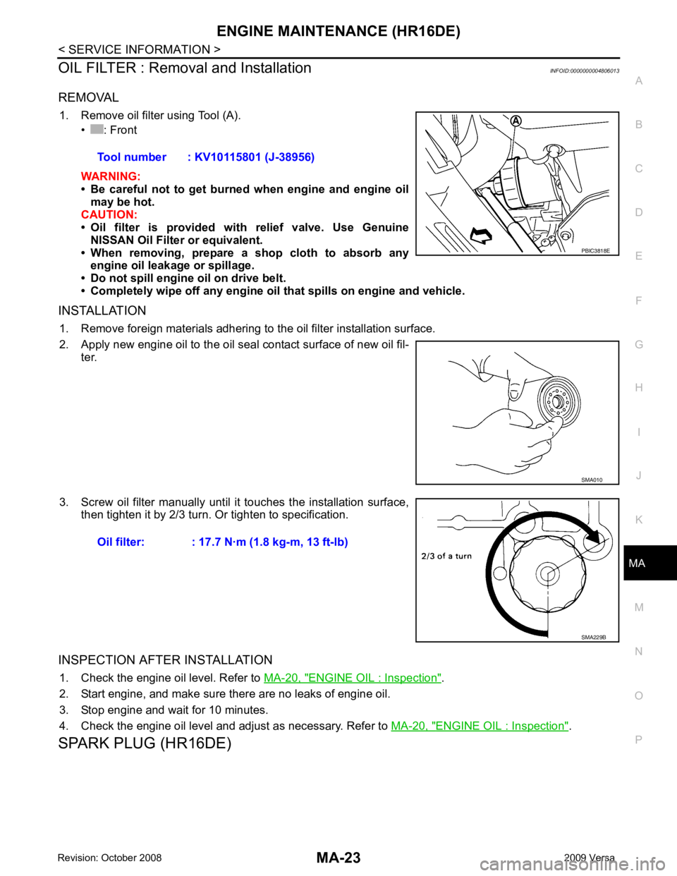
REMOVAL 1. Remove oil filter using Tool (A). • : Front
WARNING:
• Be careful not to get burned when engine and engine oil
may be hot.
CAUTION:
• Oil filter is provided with relief valve. Use Genuine
NISSAN Oil Filter or equivalent.
• When removing, prepare a s hop cloth to absorb any
engine oil leakage or spillage.
• Do not spill engine oil on drive belt.
• Completely wipe off any engine oil that spills on engine and vehicle.
INSTALLATION 1. Remove foreign materials adhering to the oil filter installation surface.
2. Apply new engine oil to the oil seal contact surface of new oil fil- ter.
3. Screw oil filter manually until it touches the installation surface,
then tighten it by 2/3 turn. Or tighten to specification.
INSPECTION AFTER INSTALLATION 1. Check the engine oil level. Refer to MA-20, " ENGINE OIL : Inspection " .
2. Start engine, and make sure there are no leaks of engine oil.
3. Stop engine and wait for 10 minutes.
4. Check the engine oil level and adjust as necessary. Refer to MA-20, " ENGINE OIL : Inspection " .
SPARK PLUG (HR16DE) Tool number : KV10115801 (J-38956) PBIC3818E
SMA010
Oil filter: : 17.7 N·m (1.8 kg-m, 13 ft-lb)
SMA229B
Page 3769 of 4331
MA-26< SERVICE INFORMATION >
ENGINE MAINTENANCE (MR18DE)
ENGINE MAINTENANCE (MR18DE)
DRIVE BELT
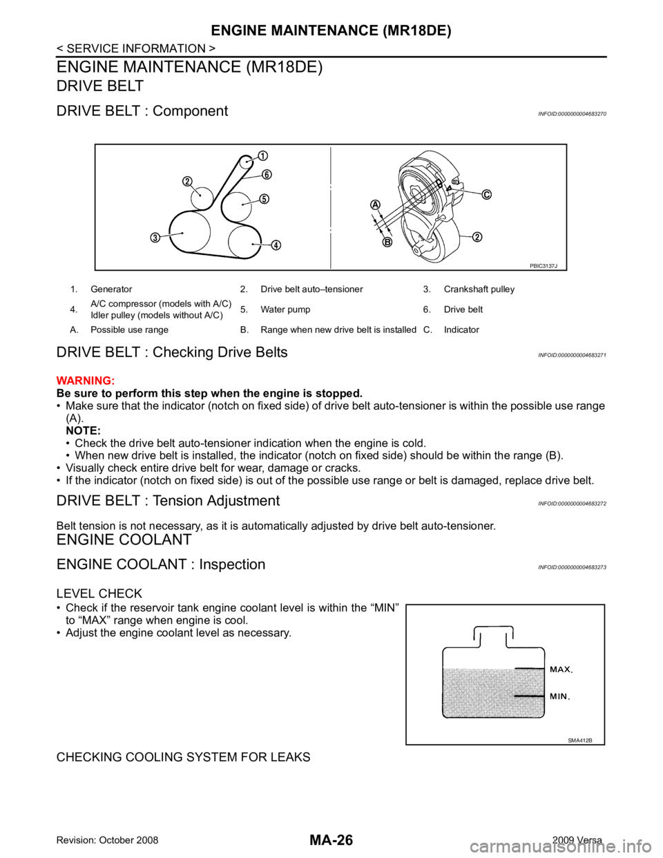
DRIVE BELT : Component INFOID:0000000004683270
DRIVE BELT : Checking Drive Belts INFOID:0000000004683271
WARNING:
Be sure to perform this step when the engine is stopped.
• Make sure that the indicator (notch on fixed side) of drive belt auto-tensioner is within the possible use range
(A).
NOTE:
• Check the drive belt auto-tensioner indication when the engine is cold.
• When new drive belt is installed, the indicator (notch on fixed side) should be within the range (B).
• Visually check entire drive belt for wear, damage or cracks.
• If the indicator (notch on fixed side) is out of t he possible use range or belt is damaged, replace drive belt.
DRIVE BELT : Tension Adjustment INFOID:0000000004683272
Belt tension is not necessary, as it is autom atically adjusted by drive belt auto-tensioner.
ENGINE COOLANT
ENGINE COOLANT : Inspection INFOID:0000000004683273
LEVEL CHECK
• Check if the reservoir tank engine coolant level is within the “MIN” to “MAX” range when engine is cool.
• Adjust the engine coolant level as necessary.
CHECKING COOLING SYSTEM FOR LEAKS 1. Generator 2. Drive belt auto–tensioner 3. Crankshaft pulley
4. A/C compressor (models with A/C)
Idler pulley (models without A/C) 5. Water pump 6. Drive belt
A. Possible use range B. Range when new drive belt is installed C. Indicator PBIC3137J
SMA412B
Page 3770 of 4331
ENGINE MAINTENANCE (MR18DE)
MA-27
< SERVICE INFORMATION >
C
D E
F
G H
I
J
K
M A
B MA
N
O P
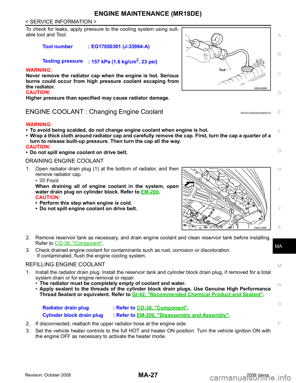
To check for leaks, apply pressure to the cooling system using suit-
able tool and Tool.
WARNING:
Never remove the radiator cap wh en the engine is hot. Serious
burns could occur from high pressure coolant escaping from
the radiator.
CAUTION:
Higher pressure than specified may cause radiator damage.
ENGINE COOLANT : Chang ing Engine Coolant INFOID:0000000004683274
WARNING:
• To avoid being scalded, do not change engine coolant when engine is hot.
• Wrap a thick cloth around radiator cap and carefully remove the cap. First, turn the cap a quarter of a
turn to release built-up pressure. Then turn the cap all the way.
CAUTION:
• Do not spill engine coolant on drive belt.
DRAINING ENGINE COOLANT 1. Open radiator drain plug (1) at the bottom of radiator, and then remove radiator cap.
• Front
When draining all of engine coolant in the system, open
water drain plug on cylinder block. Refer to EM-200 .
CAUTION:
• Perform this step when engine is cold.
• Do not spill engine coolant on drive belt.
2. Remove reservoir tank as necessary, and drain engi ne coolant and clean reservoir tank before installing.
Refer to CO-38, " Component " .
3. Check drained engine coolant for contaminants such as rust, corrosion or discoloration. If contaminated, flush the engine cooling system.
REFILLING ENGINE COOLANT 1. Install the radiator drain plug. Install the reservoir tank and cylinder block drain plug, if removed for a total
system drain or for engine removal or repair.
• The radiator must be complete ly empty of coolant and water.
• Apply sealant to the threads of the cylinder blo ck drain plugs. Use Genuine High Performance
Thread Sealant or equivalent. Refer to GI-42, " Recommended Chemical Product and Sealant " .
2. If disconnected, reattach the upper radiator hose at the engine side.
3. Set the vehicle heater controls to the full HOT and heat er ON position. Turn the vehicle ignition ON with
the engine OFF as necessary to activate the heater mode. Tool number : EG17650301 (J-33984-A)
Testing pressure : 157 kPa (1.6 kg/cm 2
, 23 psi) WBIA0568E
PBIC3799E
Radiator drain plug : Refer to
CO-38, " Component " .
Cylinder block drain plug : Refer to EM-200, " Disassembly and Assembly " .
Page 3776 of 4331
ENGINE MAINTENANCE (MR18DE)
MA-33
< SERVICE INFORMATION >
C
D E
F
G H
I
J
K
M A
B MA
N
O P
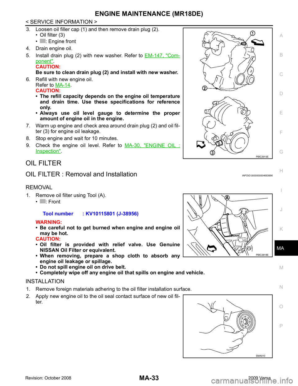
3. Loosen oil filler cap (1) and then remove drain plug (2).
• Oil filter (3)
• : Engine front
4. Drain engine oil.
5. Install drain plug (2) with new washer. Refer to EM-147, " Com-
ponent " .
CAUTION:
Be sure to clean drain plug (2 ) and install with new washer.
6. Refill with new engine oil. Refer to MA-14 .
CAUTION:
• The refill capacity depends on the engine oil temperature
and drain time. Use these sp ecifications for reference
only.
• Always use oil level gauge to determine the proper amount of engine oil in the engine.
7. Warm up engine and check area around drain plug (2) and oil fil- ter (3) for engine oil leakage.
8. Stop engine and wait for 10 minutes.
9. Check the engine oil level. Refer to MA-30, " ENGINE OIL :
Inspection " .
OIL FILTER
OIL FILTER : Remova l and Installation INFOID:0000000004683696
REMOVAL 1. Remove oil filter using Tool (A). • : Front
WARNING:
• Be careful not to get burned when engine and engine oil
may be hot.
CAUTION:
• Oil filter is provided with relief valve. Use Genuine NISSAN Oil Filter or equivalent.
• When removing, prepare a s hop cloth to absorb any
engine oil leakage or spillage.
• Do not spill engine oil on drive belt.
• Completely wipe off any engine oil that spills on engine and vehicle.
INSTALLATION 1. Remove foreign materials adhering to the oil filter installation surface.
2. Apply new engine oil to the oil seal contact surface of new oil fil- ter. PBIC3915E
Tool number : KV10115801 (J-38956)
PBIC3818E
SMA010
Page 3793 of 4331
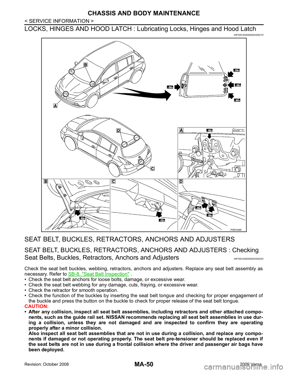
Seat Belt Inspection " .
• Check the seat belt anchors for loose bolts, damage, or excessive wear.
• Check the seat belt webbing for any damage, cuts, fraying, or excessive wear.
• Check the retractor for smooth operation.
• Check the function of the buckles by inserting the seat belt tongue and checking for proper engagement of
the buckle and press the button on the buckle to c heck for proper release of the seat belt tongue.
CAUTION:
• After any collision, inspect all seat belt assembli es, including retractors and other attached compo-
nents, such as the guide rail set. NISSAN recomme nds replacing all seat belt assemblies in use dur-
ing a collision, unless they are not damaged an d are inspected to confirm they are operating
properly after a minor collision.
Also inspect all seat belt assemblies that are not in use during a collision, and replace any compo-
nents if damaged or not operating properly. The seat belt pre-tensioner should be replaced even if
the seat belts are not in use during a frontal coll ision where the driver and passenger air bags have
been deployed.
Page 3794 of 4331

MA
N
O P
• If any component of the seat belt assembly is susp
ected of being damaged or not operating prop-
erly, do not repair the component. Replace the components as an assembly.
• If the seat belt webbing is cut, frayed, or damaged then replace the seat belt assembly.
• Never lubricate the seat belt buckle or tongue.
• When replacing any seat belt assembly alw ays use a Genuine NISSAN seat belt assembly.
Page 3795 of 4331

MT
N
O P
CONTENTS
MANUAL TRANSAXLE
RS5F91R
SERVICE INFORMATION .. ..........................
3
PRECAUTIONS .............................................. .....3
Precaution for Supplemental Restraint System
(SRS) "AIR BAG" and "SEAT BELT PRE-TEN-
SIONER" ............................................................. ......
3
PREPARATION .............................................. .....4
Special Service Tools ........................................ ......4
Commercial Service Tools ................................. ......5
NOISE, VIBRATION AND HARSHNESS
(NVH) TROUBLESHOOTING ........................ .....
7
NVH Troubleshooting Chart ................................ ......7
DESCRIPTION ............................................... .....8
System Diagram .................................................. ......8
System Description ............................................. ......8
M/T OIL ........................................................... ....10
Draining ............................................................... ....10
Refilling ............................................................... ....10
Inspection ............................................................ ....10
SIDE OIL SEAL .............................................. ....11
Removal and Installation .........................................11
POSITION SWITCH ........................................ ....12
Checking ............................................................. ....12
CONTROL LINKAGE ..................................... ....13
Exploded View .................................................... ....13
Removal and Installation .........................................13
Inspection ............................................................ ....14
AIR BREATHER HOSE .................................. ....15
Exploded View .................................................... ....15
Removal and Installation .........................................15
TRANSAXLE ASSEMBLY ............................. ....16
Exploded View .................................................... ....16 Removal and Installation .....................................
....16
Disassembly and Assembly ................................. ....17
INPUT SHAFT AND GEAR ............................... 36
Disassembly and Assembly ................................. ....36
MAINSHAFT AND GEAR ................................. 37
Disassembly and Assembly ................................. ....37
FINAL DRIVE .................................................... 41
Disassembly and Assembly ................................. ....41
SHIFT CONTROL .............................................. 42
Inspection ............................................................ ....42
SERVICE DATA AND SPECIFICATIONS
(SDS) ................................................................. 43
General Specification .......................................... ....43
RS6F94R
SERVICE INFORMATION .. .........................44
PRECAUTIONS ................................................. 44
Precaution for Supplemental Restraint System
(SRS) "AIR BAG" and "SEAT BELT PRE-TEN-
SIONER" ............................................................. ....
44
Precaution for Procedure without Cowl Top Cover ....44
Precaution ........................................................... ....44
PREPARATION ................................................. 45
Special Service Tool ............................................ ....45
Commercial Service Tool .................................... ....47
NOISE, VIBRATION AND HARSHNESS
(NVH) TROUBLESHOOTING ........................... 49
NVH Troubleshooting Chart ................................ ....49
DESCRIPTION .................................................. 50
Cross-Sectional View ...... ........................................50
M/T OIL .............................................................. 52
Changing M/T Oil ................................................. ....52
Checking M/T Oil ................................................. ....52
Page 3797 of 4331
MT
N
O P
SERVICE INFORMATION
PRECAUTIONS
Precaution for Supplemental Restraint System (SRS) "AIR BAG" and "SEAT BELT
PRE-TENSIONER" INFOID:0000000004786253
The Supplemental Restraint System such as “A IR BAG” and “SEAT BELT PRE-TENSIONER”, used along
with a front seat belt, helps to reduce the risk or severi ty of injury to the driver and front passenger for certain
types of collision. This system includes seat belt switch inputs and dual stage front air bag modules. The SRS
system uses the seat belt switches to determine the front air bag deployment, and may only deploy one front
air bag, depending on the severity of a collision and w hether the front occupants are belted or unbelted.
Information necessary to service the system safely is included in the SRS and SB section of this Service Man-
ual.
WARNING:
• To avoid rendering the SRS inoper ative, which could increase the risk of personal injury or death in
the event of a collision which would result in air bag inflation, all maintenance must be performed by
an authorized NISSAN/INFINITI dealer.
• Improper maintenance, including in correct removal and installation of the SRS can lead to personal
injury caused by unintentional act ivation of the system. For removal of Spiral Cable and Air Bag
Module, see the SRS section.
• Do not use electrical test equipm ent on any circuit related to the SRS unless instructed to in this
Service Manual. SRS wiring harnesses can be identi fied by yellow and/or orange harnesses or har-
ness connectors.
• When working near the Airbag Diagnosis Sensor Un it or other Airbag System sensors with the Igni-
tion ON or engine running, DO NOT use air or el ectric power tools or strike near the sensor(s) with a
hammer. Heavy vibration could activate the sensor( s) and deploy the air bag(s), possibly causing
serious injury.
• When using air or electric power tools or hammers , always switch the Ignition OFF, disconnect the
battery, and wait at least 3 minutes before performing any service.