belt NISSAN LATIO 2009 Service Manual PDF
[x] Cancel search | Manufacturer: NISSAN, Model Year: 2009, Model line: LATIO, Model: NISSAN LATIO 2009Pages: 4331, PDF Size: 58.04 MB
Page 3084 of 4331
![NISSAN LATIO 2009 Service Manual PDF DRIVE BELTS
EM-137
< SERVICE INFORMATION >
[MR18DE] C
D E
F
G H
I
J
K L
M A EM
NP
O
1. Hold the hexagonal part (A) of drive belt auto-tensioner (1) with
a box wrench securely. Then move the wre](/img/5/57359/w960_57359-3083.png "NISSAN LATIO 2009 Service Manual PDF DRIVE BELTS
EM-137
< SERVICE INFORMATION >
[MR18DE] C
D E
F
G H
I
J
K L
M A EM
NP
O
1. Hold the hexagonal part (A) of drive belt auto-tensioner (1) with
a box wrench securely. Then move the wre")
DRIVE BELTS
EM-137
< SERVICE INFORMATION >
[MR18DE] C
D E
F
G H
I
J
K L
M A EM
NP
O
1. Hold the hexagonal part (A) of drive belt auto-tensioner (1) with
a box wrench securely. Then move the wrench handle in the
direction of arrow (loosening direction of tensioner).
WARNING:
Never place hand in a location where pinching may occur if
the holding tool accidentally comes off.
2. Insert a rod such as short-length screwdriver approximately 6 mm (0.24 in) in diameter into the hole (B) of retaining boss to fix
drive belt auto-tensioner.
3. Install drive belt. CAUTION:
• Confirm drive belt is completely set to pulleys.
• Check for engine oil, working fluid and engine coolant are not adhered to drive belt and each
pulley groove.
4. Release drive belt auto-tensioner, and apply tension to drive belt.
5. Turn crankshaft pulley clockwise several times to equalize tension between each pulley.
6. Confirm tension of drive belt at indicator (notch on fixed side) is within the possible use range. Refer to
EM-136, " Checking Drive Belts " .
Component INFOID:0000000004307127
Removal and Installation of Drive Belt Auto Tensioner INFOID:0000000004307128
REMOVAL 1. Remove drive belt. Refer to EM-136, " Removal and Installation " .
2. Release the fixed drive belt auto-tensioner pulley.
3. Loosen bolt and remove drive belt auto-tensioner. NOTE: PBIC3936E
1. Front cover 2. Drive belt auto–tensioner 3. Idler pulley (models without A/C)
4. Bracket (models without A/C) 5. Shaft (models without A/C) PBIC4698E
Page 3108 of 4331
EM
NP
O
Removal and Installation
INFOID:0000000004307143
CAUTION:
The rotating direction indicated in the text indicates all directions seen from the engine front.
REMOVAL 1. Remove front RH wheel. Refer to WT-7, " Rotation " .
2. Remove front fender protector (RH). Refer to EI-24, " Removal and Installation " .
3. Drain engine oil. Refer to LU-17, " Changing Engine Oil " .
CAUTION:
Perform this step when engine is cold.
4. Remove the following parts. • Rocker cover: Refer to EM-153, " Component " .
• Drive belt: Refer to EM-136, " Removal and Installation " .
• Water pump pulley: Refer to CO-43, " Component " .
• Ground cable (between engine bracket (RH) and radiator core support)
5. Support the bottom surface of engine using a transmission jack, and then remove the engine bracket and insulator (RH). Refer to EM-195, " Component " .
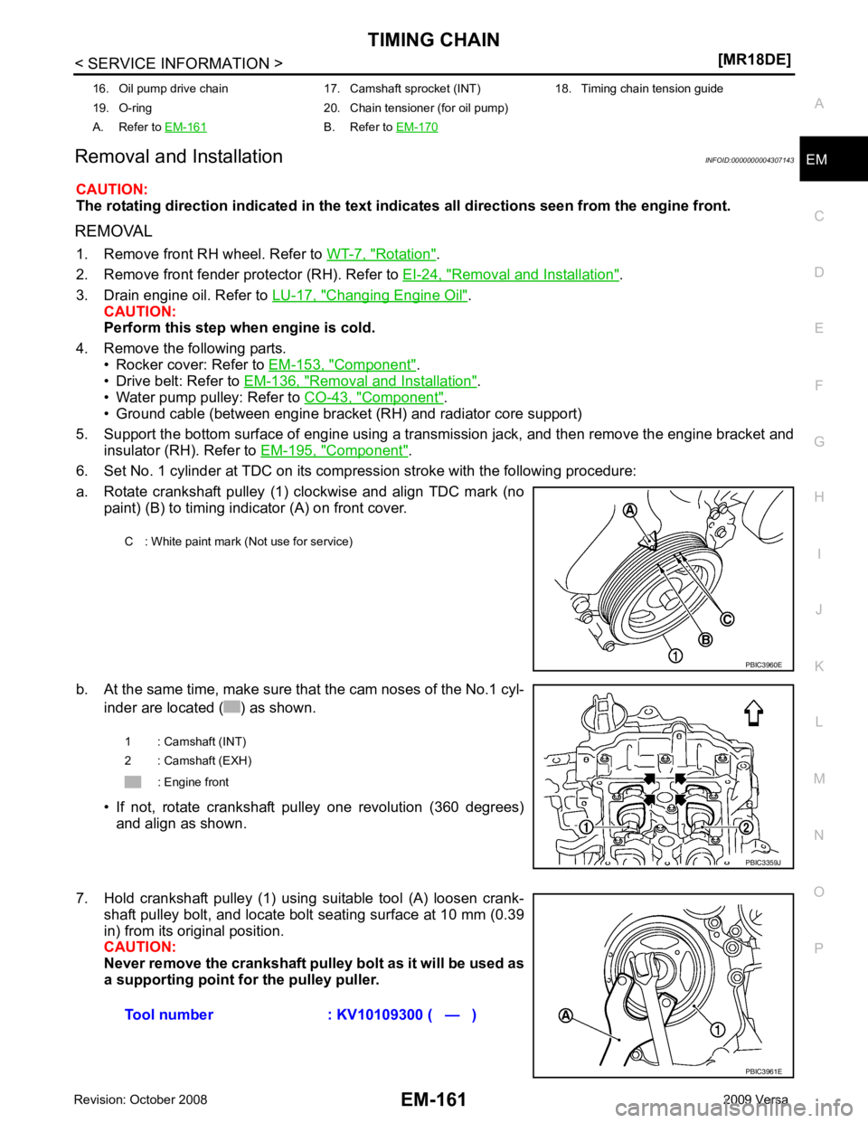
6. Set No. 1 cylinder at TDC on its compression stroke with the following procedure:
a. Rotate crankshaft pulley (1) clockwise and align TDC mark (no paint) (B) to timing indicator (A) on front cover.
b. At the same time, make sure that the cam noses of the No.1 cyl- inder are located ( ) as shown.
• If not, rotate crankshaft pulley one revolution (360 degrees) and align as shown.
7. Hold crankshaft pulley (1) using suitable tool (A) loosen crank- shaft pulley bolt, and locate bolt seating surface at 10 mm (0.39
in) from its original position.
CAUTION:
Never remove the crankshaft pulley bolt as it will be used as
a supporting point for the pulley puller.
16. Oil pump drive chain 17. Camshaft sprocket (INT) 18. Timing chain tension guide
19. O-ring 20. Chain tensioner (for oil pump)
A. Refer to EM-161 B. Refer to
EM-170 C : White paint mark (Not use for service)
Page 3109 of 4331
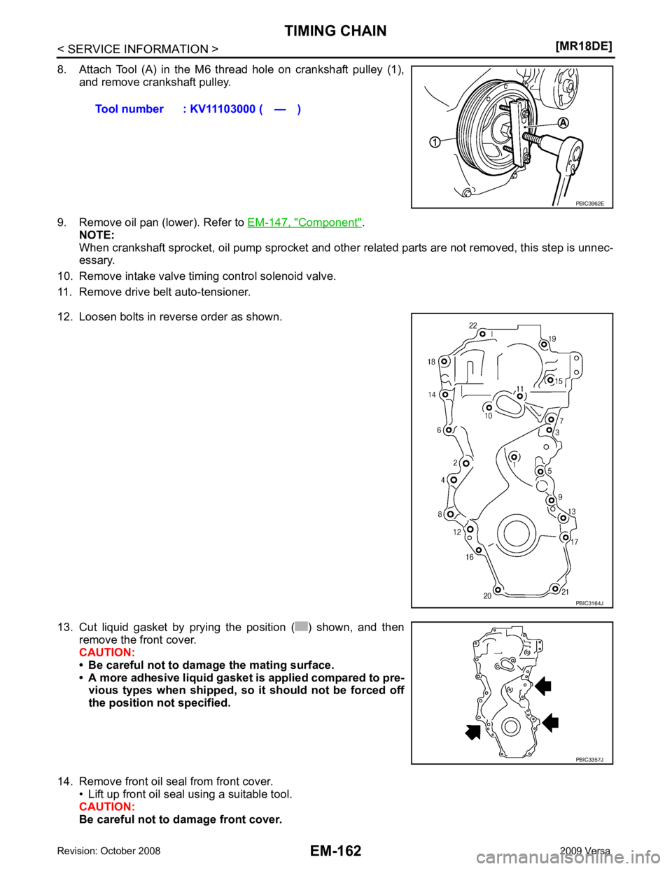
Component " .
NOTE:
When crankshaft sprocket, oil pump sprocket and other related parts are not removed, this step is unnec-
essary.
10. Remove intake valve timing control solenoid valve.
11. Remove drive belt auto-tensioner.
12. Loosen bolts in reverse order as shown.
13. Cut liquid gasket by prying the position ( ) shown, and then remove the front cover.
CAUTION:
• Be careful not to damage the mating surface.
• A more adhesive liquid gasket is applied compared to pre- vious types when shipped, so it should not be forced off
the position not specified.
14. Remove front oil seal from front cover. • Lift up front oil seal using a suitable tool.
CAUTION:
Be careful not to damage front cover. Tool number : KV11103000 ( — )
PBIC3164J
PBIC3357J
Page 3125 of 4331
Component " .
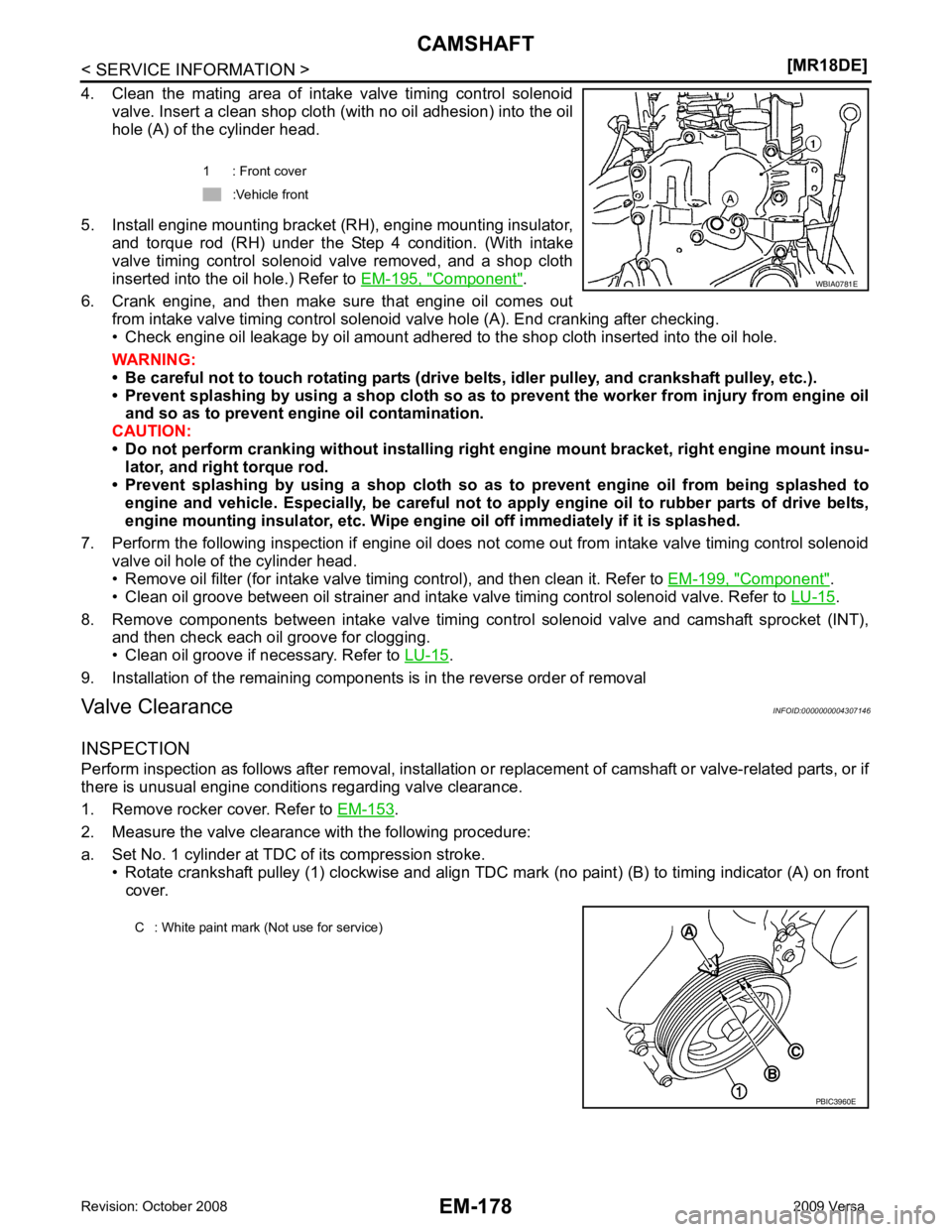
6. Crank engine, and then make sure that engine oil comes out from intake valve timing control solenoid valve hole (A). End cranking after checking.
• Check engine oil leakage by oil amount adhered to the shop cloth inserted into the oil hole.
WARNING:
• Be careful not to touch rotating parts (drive be lts, idler pulley, and crankshaft pulley, etc.).
• Prevent splashing by using a shop cloth so as to prevent the worker from injury from engine oil
and so as to prevent engi ne oil contamination.
CAUTION:
• Do not perform cranking without installing right engine mount bracket, right engine mount insu-
lator, and right torque rod.
• Prevent splashing by using a shop cloth so as to prevent engine oil from being splashed to
engine and vehicle. Especially, be careful not to apply engine oil to rubber parts of drive belts,
engine mounting insulator, etc. Wipe engi ne oil off immediately if it is splashed.
7. Perform the following inspection if engine oil does not come out from intake valve timing control solenoid valve oil hole of the cylinder head.
• Remove oil filter (for intake valve timing control), and then clean it. Refer to EM-199, " Component " .
• Clean oil groove between oil strainer and intake valve timing control solenoid valve. Refer to LU-15 .
8. Remove components between intake valve timing c ontrol solenoid valve and camshaft sprocket (INT),
and then check each oil groove for clogging.
• Clean oil groove if necessary. Refer to LU-15 .
9. Installation of the remaining components is in the reverse order of removal
Valve Clearance INFOID:0000000004307146
INSPECTION
Perform inspection as follows after removal, installation or replacement of camshaft or valve-related parts, or if
there is unusual engine conditions regarding valve clearance.
1. Remove rocker cover. Refer to EM-153 .
2. Measure the valve clearance with the following procedure:
a. Set No. 1 cylinder at TDC of its compression stroke. • Rotate crankshaft pulley (1) clockwise and align TDC mark (no paint) (B) to timing indicator (A) on front
cover. 1 : Front cover
:Vehicle front
Page 3130 of 4331
![NISSAN LATIO 2009 Service Manual PDF OIL SEAL
EM-183
< SERVICE INFORMATION >
[MR18DE] C
D E
F
G H
I
J
K L
M A EM
NP
O
• Drive belt; Refer to
EM-136, " Component " .
• Crankshaft pulley; Refer to EM-160, " Component " .
2. Remove fr](/img/5/57359/w960_57359-3129.png "NISSAN LATIO 2009 Service Manual PDF OIL SEAL
EM-183
< SERVICE INFORMATION >
[MR18DE] C
D E
F
G H
I
J
K L
M A EM
NP
O
• Drive belt; Refer to
EM-136, \" Component \" .
• Crankshaft pulley; Refer to EM-160, \" Component \" .
2. Remove fr")
OIL SEAL
EM-183
< SERVICE INFORMATION >
[MR18DE] C
D E
F
G H
I
J
K L
M A EM
NP
O
• Drive belt; Refer to
EM-136, " Component " .
• Crankshaft pulley; Refer to EM-160, " Component " .
2. Remove front oil seal using a suitable tool. CAUTION:
Be careful not to damage front cover and crankshaft.
INSTALLATION 1. Apply new engine oil to new front oil seal joint surface and seal lip.
2. Install front oil seal so that each seal lip is oriented as shown.
• Install front oil seal (2) using a suitable tool with outer diameter57 mm (2.24 in) and inner diameter 45 mm (1.77 in) (A) to the
dimension as shown.
CAUTION:
• Be careful not to damage front cover and crankshaft.
• Press-fit oil seal straight to avoid causing burrs or tilting.
• Do not touch grease applied on oil seal lip.
3. Installation of the remaining components is in the reverse order of removal.
Removal and Installation of Rear Oil Seal INFOID:0000000004307149
REMOVAL 1. Remove transaxle assembly. Refer to MT-58 (M/T models),
AT-232 (A/T models),
CVT-182 or
CVT-354 (CVT models).
2. Remove clutch cover and clutch disk (M/T models). Refer to CL-15 .
3. Remove drive plate (A/T or CVT models) or flywheel (M/T models). Refer to EM-199, " Component " .
4. Remove rear oil seal with a suitable tool. CAUTION:
Be careful not to damage crankshaft and cylinder block.
INSTALLATION 1. Apply the liquid gasket lightly to entire outside area of new rear oil seal. Use Genuine Silicone RTV Seal ant or equivalent. Refer to GI-42, " Recommended Chemical Prod-
uct and Sealant " .
A : Dust seal lip
B : Oil seal lip
: Engine front
: Engine rear PBIC3485J
1 : Front cover
: Engine front
Within 0.3 mm (0.012 in) toward engine front
Within 0.5 mm (0.020 in) toward engine rear PBIC3729E
Page 3133 of 4331
Trouble Diagnosis Introduction "
(Type 1) or
EC-1089, " Trouble Diagnosis Introduction " (Type 2).
Component INFOID:0000000004307151
Removal and Installation INFOID:0000000004307152
REMOVAL
WARNING:
• Put a “CAUTION: FLAMMABLE” sign in the workshop.
• Be sure to work in a well ventilate d area and furnish workshop with a CO
2 fire extinguisher.
• Do not smoke while servicing fuel system. Keep open flames and sparks away from the work area.
1. Release the fuel pressure. Refer to EC-574, " Fuel Pressure Check " (Type 1) or
EC-1086, " Fuel Pressure
Check " (Type 2).
2. Drain engine coolant and engine oil. Refer to CO-35 and
LU-16 .
CAUTION:
• Perform this step when the engine is cold.
• Never spill engine coolant an d engine oil on drive belt.
3. Remove front fender protector (RH). Refer to EI-24 .
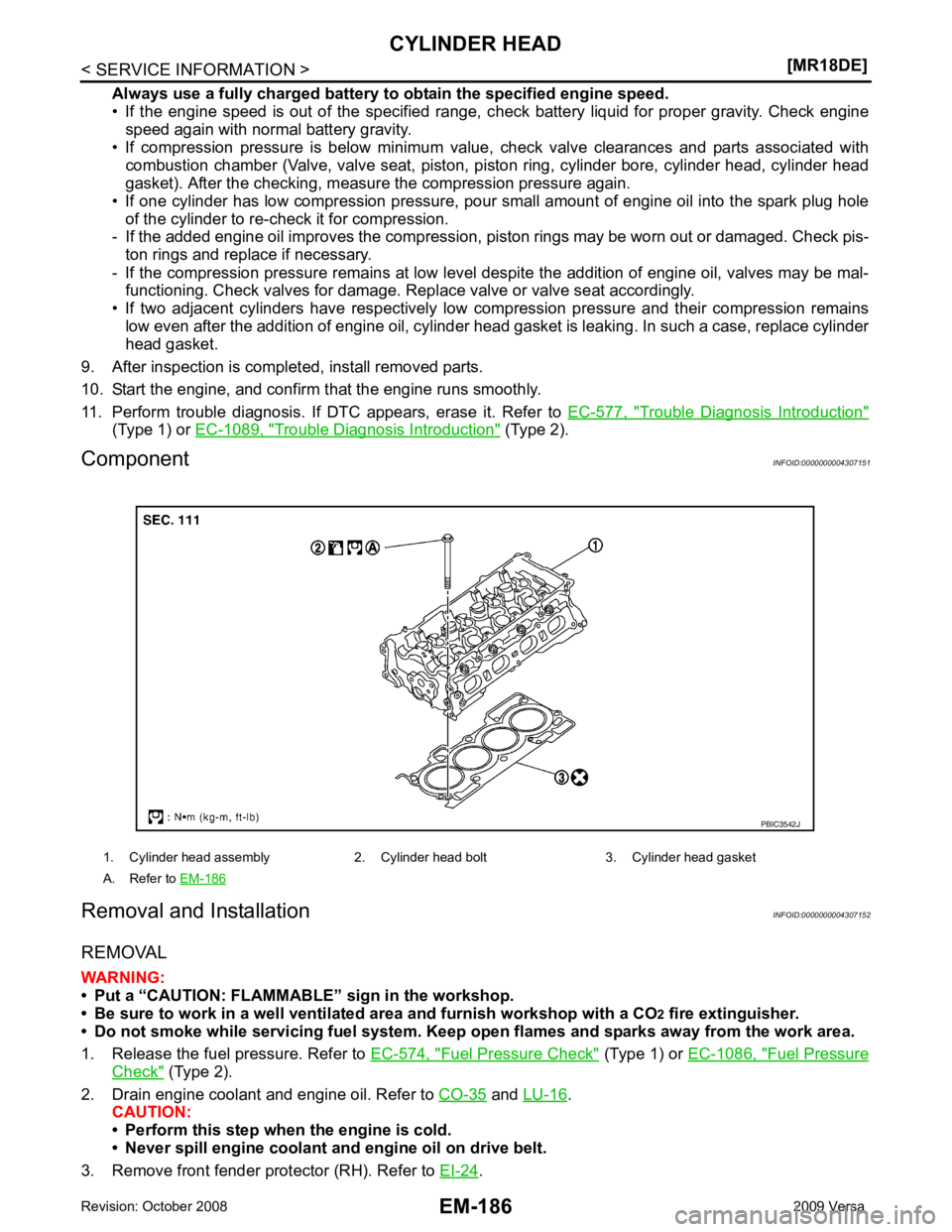
1. Cylinder head assembly 2. Cylinder head bolt 3. Cylinder head gasket
A. Refer to EM-186
Page 3134 of 4331
![NISSAN LATIO 2009 Service Manual PDF CYLINDER HEAD
EM-187
< SERVICE INFORMATION >
[MR18DE] C
D E
F
G H
I
J
K L
M A EM
NP
O
4. Remove drive belt. Refer to
EM-136, " Removal and Installation " .
5. Remove the following components and rela](/img/5/57359/w960_57359-3133.png "NISSAN LATIO 2009 Service Manual PDF CYLINDER HEAD
EM-187
< SERVICE INFORMATION >
[MR18DE] C
D E
F
G H
I
J
K L
M A EM
NP
O
4. Remove drive belt. Refer to
EM-136, \" Removal and Installation \" .
5. Remove the following components and rela")
CYLINDER HEAD
EM-187
< SERVICE INFORMATION >
[MR18DE] C
D E
F
G H
I
J
K L
M A EM
NP
O
4. Remove drive belt. Refer to
EM-136, " Removal and Installation " .
5. Remove the following components and related parts. • Exhaust manifold; Refer to EM-144 .
• Intake manifold; Refer to EM-141 .
• Fuel tube and fuel injector assembly; Refer to EM-156 .
• Water outlet; Refer to CO-47 .
• Rocker cover; Refer to EM-153 .
• Front cover, timing chain; Refer to EM-160 .
• Camshaft; Refer to EM-170 .
6. Remove cylinder head. • Loosen bolts in reverse order as shown.
• Using TORX socket (size E18), loosen cylinder head bolts.
7. Remove cylinder head gasket.
INSPECTION AFTER REMOVAL
Cylinder Head Bolts Outer Diameter • Cylinder head bolts are tightened by plastic zone tightening method. Whenever the size difference between (d1) and (d2)
exceeds the limit, replac e them with a new one.
• If reduction of outer diameter appear s in a position other than (d2),
use it as (d2) point.
Cylinder Head Distortion NOTE:
When performing this inspection, cylinder block distortion should be also checked. Refer to EM-216, " Inspec-
tion After Disassembly " .
1. Wipe off engine oil and remove water scale (like deposit ), gasket, sealant, carbon, etc. with a scraper.
CAUTION:
Never allow gasket debris to enter passag es for engine oil or engine coolant.
2. At each of several locations on bottom surface of cylinder head, measure the distortion in six di rections using straightedge (A)
and feeler gauge (B).
• If it exceeds the limit, replace cylinder head.
INSTALLATION 1. Install cylinder head gasket.
2. Apply new engine oil to threads and seating surface of bolts. CAUTION: : Engine front
PBIC3206J
Limit [(d1) – (d2)]: 0.15 mm (0.0059 in)
PBIC3994E
Limit: 0.1 mm (0.004 in)
PBIC3207J
Page 3143 of 4331
Garage Jack and
Safety Stand and 2-Pole Lift " .
REMOVAL
Remove the engine and the transaxle assembly from t he vehicle downward. Separate the engine and the tran-
saxle.
1. Remove engine undercover.
2. Drain engine coolant from radiator. Refer to CO-35, " Changing Engine Coolant " .
CAUTION:
• Perform this step when the engine is cold.
• Do not spill engine coolant on drive belt.
3. Remove front fender protector (RH and LH). Refer to EI-24 .
4. Remove exhaust front tube. Refer to EX-9 .
5. Remove drive shafts (LH and RH) from steering knuckle. Refer to FAX-9 .
6. Remove transaxle joint bolts which pierce at oil pan (upper) lower rear side. Refer to AT-232 (A/T models),
CVT-182 or
CVT-354 (CVT models) or
MT-58 (M/T models).
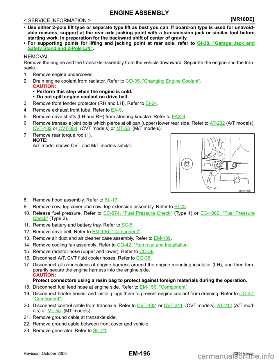
7. Remove rear torque rod (1). NOTE:
A/T model shown CVT and M/T models similar.
8. Remove hood assembly. Refer to BL-13 .
9. Remove cowl top cover and cowl top extension assembly. Refer to EI-22 .
10. Release fuel pressure. Refer to EC-574, " Fuel Pressure Check " (Type 1) or
EC-1086, " Fuel Pressure
Check " (Type 2).
11. Remove battery and battery tray. Refer to SC-5 .
12. Remove drive belt; Refer to EM-136, " Component " .
13. Remove air duct and air cleaner case assembly. Refer to EM-139 .
14. Remove cooling fan assembly. Refer to CO-42, " Removal and Installation " .
15. Remove radiator hose (upper and lower). Refer to CO-38 .
16. Disconnect A/T, CVT fluid cooler hoses. Refer to CO-38 .
17. Disconnect all connections of engine harness around the engine mounting insulator (LH), and then tem- porarily secure the engine harness into the engine side.
CAUTION:
Protect connectors using a resin bag to protect against foreign materials during the operation.
18. Disconnect fuel feed hose at engine side. Refer to EM-156, " Component " .
19. Disconnect heater hoses, and install plugs them to prevent engine coolant from draining. Refer to CO-47," Component " .
20. Disconnect control cable from transaxle. Refer to CVT-182 or
CVT-341 (CVT models),
AT-212 (A/T mod-
els) or MT-55 (MT models).
21. Remove ground cable at transaxle side.
22. Remove ground cable between front cover and vehicle.
23. Remove generator. Refer to SC-21 .
Page 3174 of 4331

EM
NP
O
SERVICE DATA AND SPECIFICATIONS (SDS)
Standard and Limit INFOID:0000000004307162
GENERAL SPECIFICATIONS
DRIVE BELT
WATER CONTROL VALVE
EXHAUST MANIFOLD Unit: mm (in)
THERMOSTAT
SPARK PLUG Unit: mm (in)
CYLINDER HEAD Unit: mm (in)
Engine type
MR18DE
Cylinder arrangement In-line 4
Displacement cm3
(cu in) 1,797 (109.65)
Bore and stroke mm (in) 84.0 x 81.1 (3.307 x 3.192)
Valve arrangement DOHC
Firing order 1-3-4-2
Number of piston rings Compression 2
Oil 1
Compression ratio 9.9
Compression pressure
kPa (bar, kg/cm 2
, psi) / 250 rpm Standard 1,500 (15.0, 15.3, 217.6)
Minimum 1,200 (12.0, 12.2, 174)
Differential limit between cylinders 100 (1.0, 1.0, 15) Tension of drive belt Auto adjustment by auto-tensioner
Valve opening temperature 93.5 - 96.5
°C (200 - 206 °F)
Full-open valve lift amount 8 mm/ 108 °C (0.315 in/ 226 °F)
Valve closing temperature More than 90 °C (194 °F) Items
Limit
Surface distortion Each exhaust port 0.3 (0.012)
Entire part 0.7 (0.028) Valve opening temperature 80.5 - 83.5
°C (177 - 182 °F)
Full-open valve lift amount 8 mm/ 95 °C (0.315 in/ 203 °F)
Valve closing temperature More than 77 °C (171 °F) Make
DENSO
Standard type FXE20HR11
Spark plug gap Nominal: 1.1 (0.043)Items Standard Limit
Head surface distortion — 0.1 (0.004)
Normal cylinder head height (H) 130.9 (5.15) —
Page 3185 of 4331

EX
N
O P
CONTENTS
EXHAUST SYSTEM
HR16DE
PRECAUTION ....... ........................................
2
PRECAUTIONS .............................................. .....2
Precaution for Supplemental Restraint System
(SRS) "AIR BAG" and "SEAT BELT PRE-TEN-
SIONER" ............................................................. ......
2
Precaution Necessary fo r Steering Wheel Rota-
tion After Battery Disconnect ............................... ......
2
PREPARATION .... ........................................3
PREPARATION .............................................. .....3
Special Service Tool ........................................... ......3
Commercial Service Tool .................................... ......3
ON-VEHICLE MAINTENA NCE .....................4
EXHAUST SYSTEM ....................................... .....4
Checking Exhaust System .................................. ......4
ON-VEHICLE REPAIR .... ..............................5 EXHAUST SYSTEM
........................................... 5
Component .......................................................... .....5
Removal and Installation ..................................... .....5
MR18DE
SERVICE INFORMATION .. ..........................7
PRECAUTIONS .................................................. 7
Precaution for Supplemental Restraint System
(SRS) "AIR BAG" and "SEAT BELT PRE-TEN-
SIONER" ............................................................. .....
7
Precaution Necessary for Steering Wheel Rota-
tion After Battery Disconnect ............................... .....
7
PREPARATION .................................................. 8
Special Service Tool ............................................ .....8
Commercial Service Tool .................................... .....8
EXHAUST SYSTEM ........................................... 9
Checking Exhaust System ................................... .....9
Component .......................................................... .....9
Removal and Installation ..................................... .....9