ground NISSAN LATIO 2009 Service User Guide
[x] Cancel search | Manufacturer: NISSAN, Model Year: 2009, Model line: LATIO, Model: NISSAN LATIO 2009Pages: 4331, PDF Size: 58.04 MB
Page 116 of 4331
AT
N
O P
5. Accelerate vehicle to 20 to 25 km/h (12 to 16 MPH) under the following conditions and release the accel-
erator pedal completely.
THROTTLE POSI: Less th an 1.0/8 (at all times during step 4)
SLCT LVR POSI: “D” position
- Make sure that “GEAR” shows “2” after releasing pedal.
6. Depress accelerator pedal to WOT (more than 7.0/ 8 of “THROTTLE POSI”) quickly from a speed of 20 to
25 km/h (12 to 16 MPH) until “TESTING” changes to “STOP VEHICLE” or “COMPLETED”. (It will take
approximately 3 seconds.)
If the check result NG appears on CONSULT-III screen, go to AT-111, " Diagnosis Procedure " .
If “STOP VEHICLE” appears on CONSULT-III screen, go to the following step.
- Make sure that “GEAR” shows “1” when depressing accelerator pedal to WOT.
- If “TESTING” does not appear on CONSULT-III fo r a long time, select “SELF-DIAG RESULTS” for
“TRANSMISSION”. In case a DTC other than “P0731 A/T 1ST GR FNCTN” is shown, refer to AT-79," CONSULT-III Function (TRANSMISSION) " .
7. Stop vehicle.
8. Follow the instruction displayed. (Check for normal shifting referring to the table below.)
9. Make sure that “OK” is disp layed. (If “NG” is displayed, refer to “Diagnostic Procedure”.)
Refer to AT-111, " Diagnosis Procedure " .
Refer to AT-64, " Vehicle Speed at Which Gear Shifting Occurs " .
WITH GST
Follow the procedure “WITH CONSULT-III”.
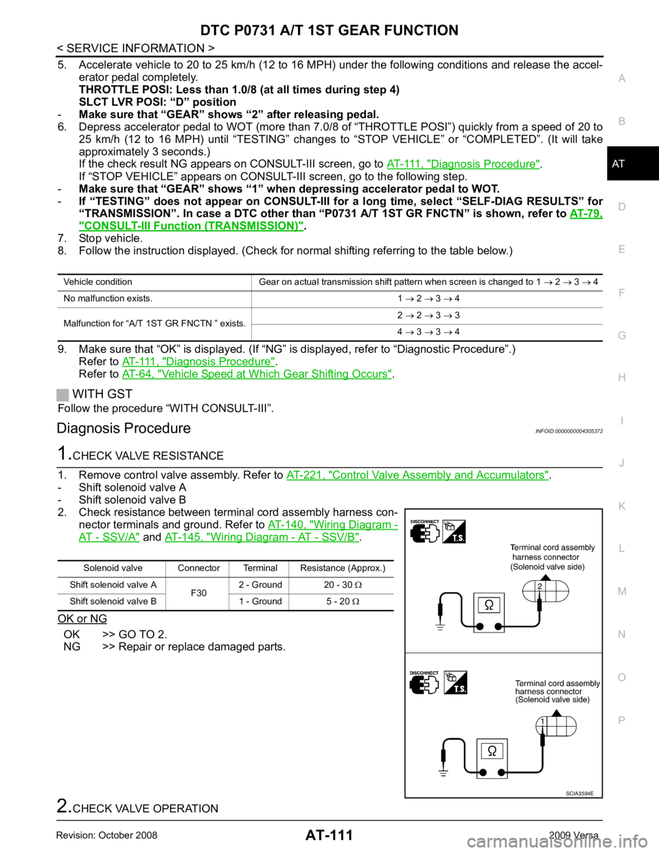
Diagnosis Procedure INFOID:0000000004305372Control Valve Assembly and Accumulators " .
- Shift solenoid valve A
- Shift solenoid valve B
2. Check resistance between terminal cord assembly harness con- nector terminals and ground. Refer to AT-140, " Wiring Diagram -
AT - SSV/A " and
AT-145, " Wiring Diagram - AT - SSV/B " .
OK or NG OK >> GO TO 2.
NG >> Repair or replace damaged parts. Solenoid valve Connector Terminal Resistance (Approx.)
Shift solenoid valve A F302 - Ground 20 - 30
Ω
Shift solenoid valve B 1 - Ground 5 - 20 Ω
Page 117 of 4331
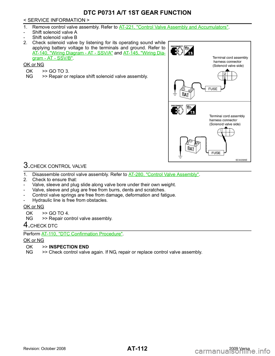
Control Valve Assembly and Accumulators " .
- Shift solenoid valve A
- Shift solenoid valve B
2. Check solenoid valve by listening for its operating sound while
applying battery voltage to the terminals and ground. Refer to
AT-140, " Wiring Diagram - AT - SSV/A " and
AT-145, " Wiring Dia-
gram - AT - SSV/B " .
OK or NG OK >> GO TO 3.
NG >> Repair or replace shift solenoid valve assembly. Control Valve Assembly " .
2. Check to ensure that:
- Valve, sleeve and plug slide along valve bore under their own weight.
- Valve, sleeve and plug are free from burrs, dents and scratches.
- Control valve springs are free from damage, deformation and fatigue.
- Hydraulic line is free from obstacles.
OK or NG OK >> GO TO 4.
NG >> Repair control valve assembly. DTC Confirmation Procedure " .
OK or NG OK >>
INSPECTION END
NG >> Check control valve again. If NG, repair or replace control valve assembly.
Page 119 of 4331
Diagnosis Procedure " .
If “STOP VEHICLE” appears on CONSUL T-III screen, go to following step.
- Make sure that “GEAR” shows “2” wh en depressing accelerator pedal to WOT.
- If “TESTING” does not appear on CONSULT-III fo r a long time, select “SELF-DIAG RESULTS” for
“TRANSMISSION”. In case a DTC other than “P0732 A/T 2ND GR FNCTN” is shown, refer to AT-79," CONSULT-III Function (TRANSMISSION) " .
7. Stop vehicle.
8. Follow the instruction displayed. (Check for normal shifting referring to the table below.)
9. Make sure that “OK” is displayed. (If “NG” is displayed, refer to “Diagnostic Procedure”.)
Refer to AT-114, " Diagnosis Procedure " .
Refer to AT-64, " Vehicle Speed at Which Gear Shifting Occurs " .
WITH GST
Follow the procedure “WITH CONSULT-III”.
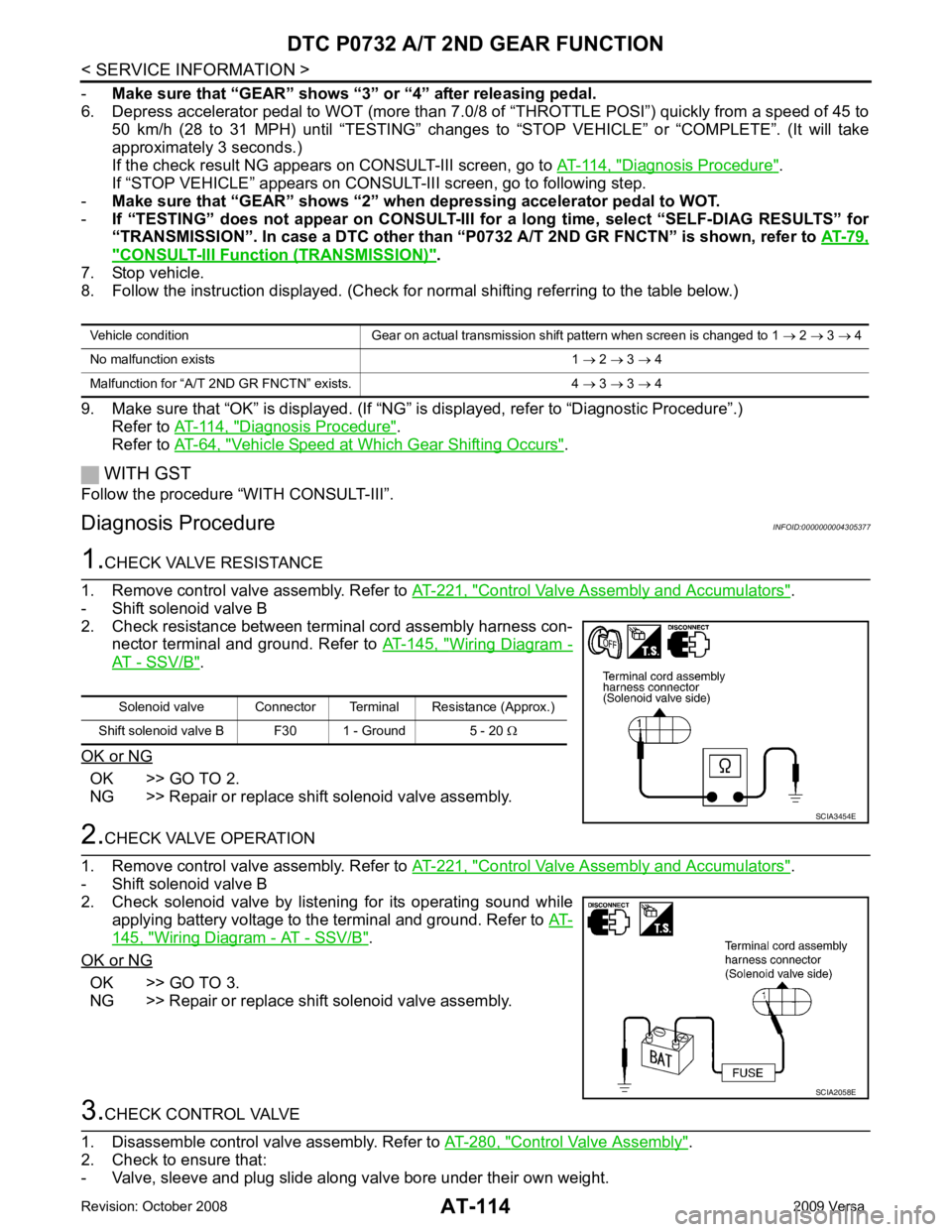
Diagnosis Procedure INFOID:0000000004305377Control Valve Assembly and Accumulators " .
- Shift solenoid valve B
2. Check resistance between terminal cord assembly harness con- nector terminal and ground. Refer to AT-145, " Wiring Diagram -
AT - SSV/B " .
OK or NG OK >> GO TO 2.
NG >> Repair or replace shift solenoid valve assembly. Control Valve Assembly and Accumulators " .
- Shift solenoid valve B
2. Check solenoid valve by listening for its operating sound while applying battery voltage to the terminal and ground. Refer to AT-145, " Wiring Diagram - AT - SSV/B " .
OK or NG OK >> GO TO 3.
NG >> Repair or replace shift solenoid valve assembly. Control Valve Assembly " .
2. Check to ensure that:
- Valve, sleeve and plug slide along valve bore under their own weight. Vehicle condition Gear on actual transmission shift pattern when screen is changed to 1
→ 2 → 3 → 4
No malfunction exists 1 → 2 → 3 → 4
Malfunction for “A/T 2ND GR FNCTN” exists. 4 → 3 → 3 → 4 Solenoid valve Connector Terminal Resistance (Approx.)
Shift solenoid valve B F30 1 - Ground 5 - 20 Ω SCIA2058E
Page 122 of 4331
DTC P0733 A/T 3RD GEAR FUNCTION
AT-117
< SERVICE INFORMATION >
D
E
F
G H
I
J
K L
M A
B AT
N
O P
-
Make sure that “GEAR” shows “4” after releasing pedal.
6. Depress accelerator pedal steadily with 3.5/8 - 4.5/ 8 of “THROTTLE POSI” from a speed of 60 to 75 km/h
(37 to 47 MPH) until “TESTING” changes to “STOP VE HICLE” or “COMPLETED”. (It will take approxi-
mately 3 seconds.)
If the check result NG appears on CONSULT-III screen, go to AT-117, " Diagnosis Procedure " .
If “STOP VEHICLE” appears on CONSULT-III screen, go to following step.
- Make sure that “GEAR” shows “3” when depr essing accelerator pedal with 3.5/8 - 4.5/8 of
“THROTTLE POSI”.
- If “TESTING” does not appear on CONSULT-III fo r a long time, select “SELF-DIAG RESULTS” for
“TRANSMISSION”. In case a DTC ot her than “P0733 A/T 3RD GR FNCTN” is shown, refer to AT-79," CONSULT-III Function (TRANSMISSION) " .
7. Stop vehicle.
8. Follow the instruction displayed. (Check for normal shifting referring to the table below.)
9. Make sure that “OK” is disp layed. (If “NG” is displayed, refer to “Diagnostic Procedure”.)
Refer to AT-117, " Diagnosis Procedure " .
Refer to AT-64, " Vehicle Speed at Which Gear Shifting Occurs " .
WITH GST
Follow the procedure “WITH CONSULT-III”.
Diagnosis Procedure INFOID:00000000043053821.
CHECK VALVE RESISTANCE
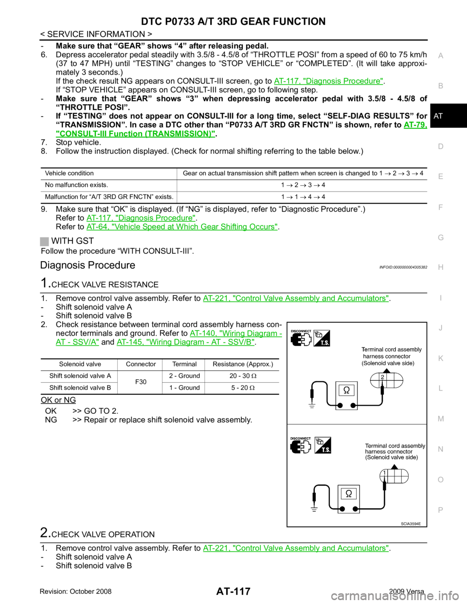
1. Remove control valve assembly. Refer to AT-221, " Control Valve Assembly and Accumulators " .
- Shift solenoid valve A
- Shift solenoid valve B
2. Check resistance between terminal cord assembly harness con- nector terminals and ground. Refer to AT-140, " Wiring Diagram -
AT - SSV/A " and
AT-145, " Wiring Diagram - AT - SSV/B " .
OK or NG OK >> GO TO 2.
NG >> Repair or replace shift solenoid valve assembly. 2.
CHECK VALVE OPERATION
1. Remove control valve assembly. Refer to AT-221, " Control Valve Assembly and Accumulators " .
- Shift solenoid valve A
- Shift solenoid valve B Vehicle condition Gear on actual transmission shift pattern when screen is changed to 1
→ 2 → 3 → 4
No malfunction exists. 1 → 2 → 3 → 4
Malfunction for “A/T 3 RD GR FNCTN” exists. 1 → 1 → 4 → 4 Solenoid valve Connector Terminal Resistance (Approx.)
Shift solenoid valve A F302 - Ground 20 - 30
Ω
Shift solenoid valve B 1 - Ground 5 - 20 Ω SCIA3594E
Page 123 of 4331
AT-118< SERVICE INFORMATION >
DTC P0733 A/T 3RD GEAR FUNCTION
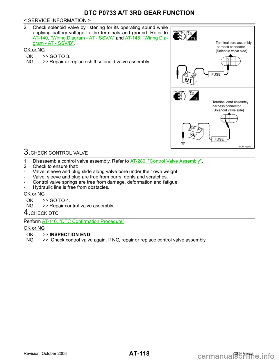
2. Check solenoid valve by listening for its operating sound while applying battery voltage to the terminals and ground. Refer to
AT-140, " Wiring Diagram - AT - SSV/A " and
AT-145, " Wiring Dia-
gram - AT - SSV/B " .
OK or NG OK >> GO TO 3.
NG >> Repair or replace shift solenoid valve assembly. 3.
CHECK CONTROL VALVE
1. Disassemble control valve assembly. Refer to AT-280, " Control Valve Assembly " .
2. Check to ensure that:
- Valve, sleeve and plug slide along valve bore under their own weight.
- Valve, sleeve and plug are free from burrs, dents and scratches.
- Control valve springs are free from damage, deformation and fatigue.
- Hydraulic line is free from obstacles.
OK or NG OK >> GO TO 4.
NG >> Repair control valve assembly. 4.
CHECK DTC
Perform AT-116, " DTC Confirmation Procedure " .
OK or NG OK >>
INSPECTION END
NG >> Check control valve again. If NG, repair or replace control valve assembly. SCIA3595E
Page 126 of 4331
DTC P0734 A/T 4TH GEAR FUNCTION
AT-121
< SERVICE INFORMATION >
D
E
F
G H
I
J
K L
M A
B AT
N
O P 3.
CHECK VALVE RESISTANCE
1. Remove control valve assembly. Refer to AT-221, " Control Valve Assembly and Accumulators " .
- Shift solenoid valve A
- Shift solenoid valve B
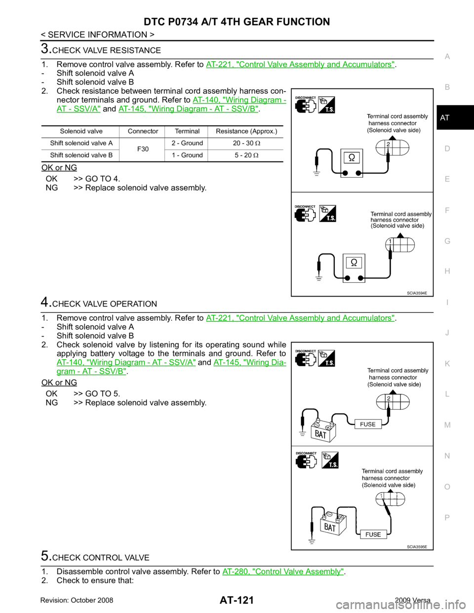
2. Check resistance between terminal cord assembly harness con- nector terminals and ground. Refer to AT-140, " Wiring Diagram -
AT - SSV/A " and
AT-145, " Wiring Diagram - AT - SSV/B " .
OK or NG OK >> GO TO 4.
NG >> Replace solenoid valve assembly. 4.
CHECK VALVE OPERATION
1. Remove control valve assembly. Refer to AT-221, " Control Valve Assembly and Accumulators " .
- Shift solenoid valve A
- Shift solenoid valve B
2. Check solenoid valve by listening for its operating sound while applying battery voltage to the terminals and ground. Refer to
AT-140, " Wiring Diagram - AT - SSV/A " and
AT-145, " Wiring Dia-
gram - AT - SSV/B " .
OK or NG OK >> GO TO 5.
NG >> Replace solenoid valve assembly. 5.
CHECK CONTROL VALVE
1. Disassemble control valve assembly. Refer to AT-280, " Control Valve Assembly " .
2. Check to ensure that: Solenoid valve Connector Terminal Resistance (Approx.)
Shift solenoid valve A F302 - Ground 20 - 30
Ω
Shift solenoid valve B 1 - Ground 5 - 20 Ω SCIA3594E
SCIA3595E
Page 127 of 4331
AT-122< SERVICE INFORMATION >
DTC P0734 A/T 4TH GEAR FUNCTION
- Valve, sleeve and plug slide along valve bore under their own weight.
- Valve, sleeve and plug are free from burrs, dents and scratches.
- Control valve springs are free from damage, deformation and fatigue.
- Hydraulic line is free from obstacles.
OK or NG OK >> GO TO 6.
NG >> Repair control valve. 6.
CHECK SHIFT-UP (D 3 TO D 4)
During AT-58, " Cruise Test - Part 1 " .
Does A/T shift from D 3 to D 4 at the specified speed?
YES >> GO TO 11.
NO >> Check control valve again. Repair or replace control
valve assembly. 7.
CHECK VALVE RESISTANCE
1. Remove control valve assembly. Refer to AT-221, " Control Valve Assembly and Accumulators " .
- Line pressure solenoid valves
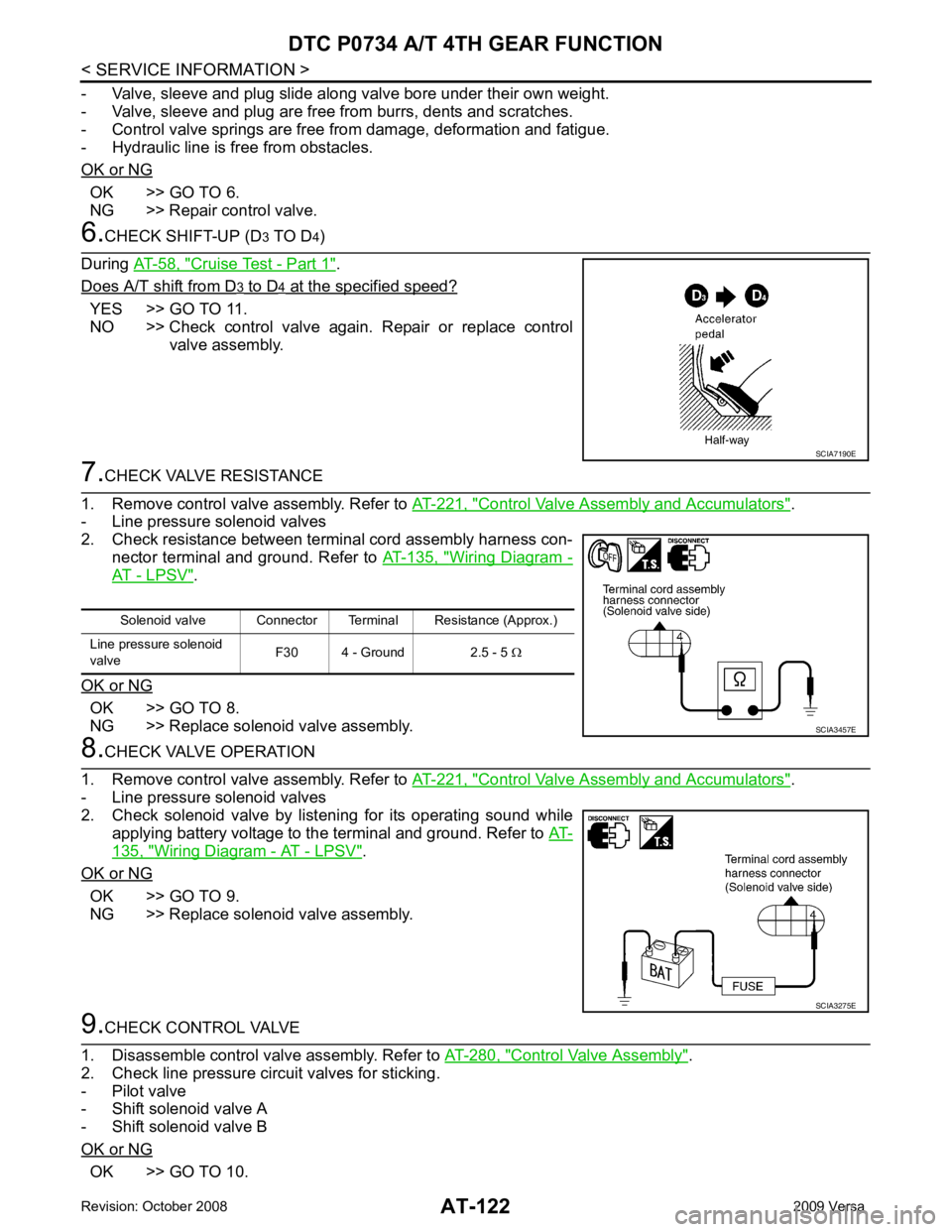
2. Check resistance between terminal cord assembly harness con- nector terminal and ground. Refer to AT-135, " Wiring Diagram -
AT - LPSV " .
OK or NG OK >> GO TO 8.
NG >> Replace solenoid valve assembly. 8.
CHECK VALVE OPERATION
1. Remove control valve assembly. Refer to AT-221, " Control Valve Assembly and Accumulators " .
- Line pressure solenoid valves
2. Check solenoid valve by listening for its operating sound while
applying battery voltage to the terminal and ground. Refer to AT-135, " Wiring Diagram - AT - LPSV " .
OK or NG OK >> GO TO 9.
NG >> Replace solenoid valve assembly. 9.
CHECK CONTROL VALVE
1. Disassemble control valve assembly. Refer to AT-280, " Control Valve Assembly " .
2. Check line pressure circuit valves for sticking.
- Pilot valve
- Shift solenoid valve A
- Shift solenoid valve B
OK or NG OK >> GO TO 10. SCIA7190E
Solenoid valve Connector Terminal Resistance (Approx.)
Line pressure solenoid
valve F30 4 - Ground 2.5 - 5
Ω SCIA3457E
SCIA3275E
Page 131 of 4331
OK >> GO TO 5.
NG >> GO TO 2. OK >> GO TO 5.
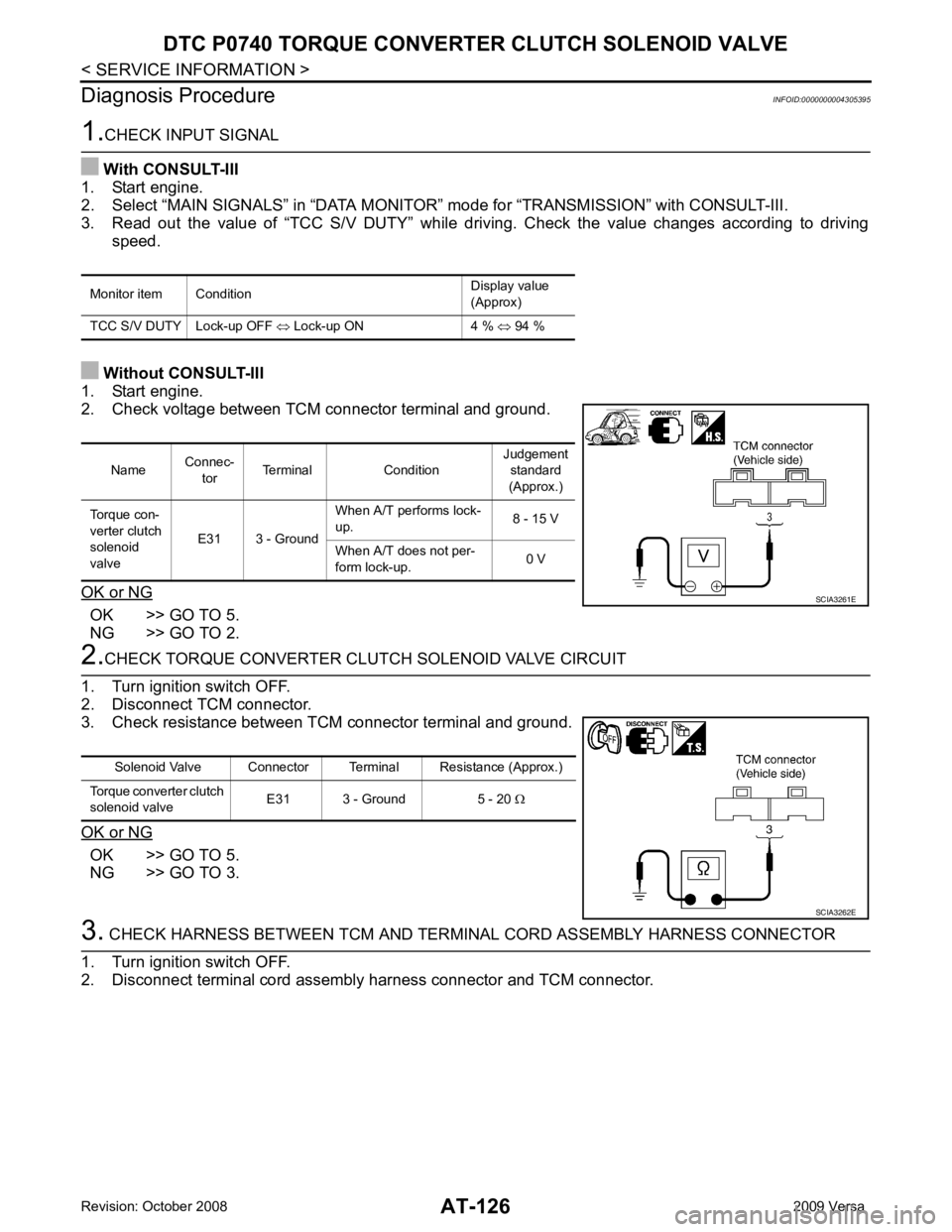
NG >> GO TO 3. Name
Connec-
tor Terminal Condition Judgement
standard
(Approx.)
Torque con-
verter clutch
solenoid
valve E31 3 - Ground When A/T performs lock-
up. 8 - 15 V
When A/T does not per-
form lock-up. 0 V
Page 132 of 4331
AT
N
O P
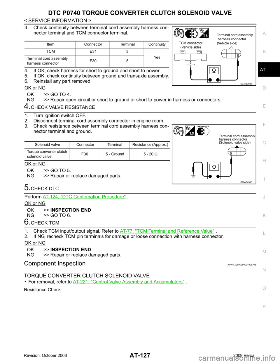
3. Check continuity between terminal cord assembly harness con-
nector terminal and TCM connector terminal.
4. If OK, check harness for short to ground and short to power.
5. If OK, check continuity between ground and transaxle assembly.
6. Reinstall any part removed.
OK or NG OK >> GO TO 4.
NG >> Repair open circuit or short to ground or short to power in harness or connectors. OK >> GO TO 5.
NG >> Repair or replace damaged parts. DTC Confirmation Procedure " .
OK or NG OK >>
INSPECTION END
NG >> GO TO 6. TCM Terminal and Reference Value " .
2. If NG, recheck TCM pin terminals for dam age or loose connection with harness connector.
OK or NG OK >>
INSPECTION END
NG >> Repair or replace damaged parts.
Component Inspection INFOID:0000000004305396
TORQUE CONVERTER CLUTCH SOLENOID VALVE • For removal, refer to AT-221, " Control Valve Assembly and Accumulators " .
Resistance Check Item Connector Terminal Continuity
TCM E31 3 Yes
Terminal cord assembly
harness connector F30 5
Page 136 of 4331
DTC P0744 A/T TCC S/
V FUNCTION (LOCK-UP)
AT-131
< SERVICE INFORMATION >
D
E
F
G H
I
J
K L
M A
B AT
N
O P
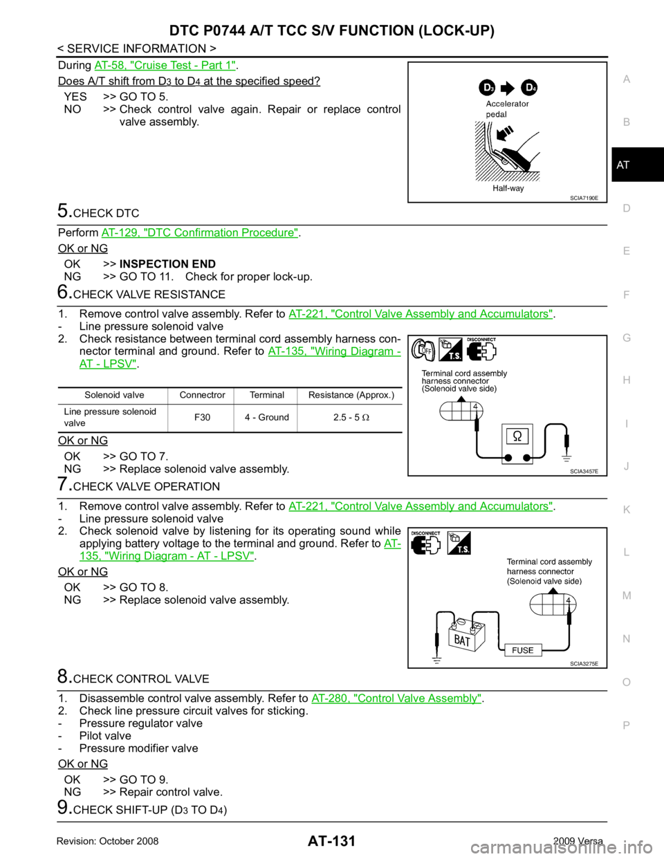
During
AT-58, " Cruise Test - Part 1 " .
Does A/T shift from D 3 to D 4 at the specified speed?
YES >> GO TO 5.
NO >> Check control valve again. Repair or replace control valve assembly. 5.
CHECK DTC
Perform AT-129, " DTC Confirmation Procedure " .
OK or NG OK >>
INSPECTION END
NG >> GO TO 11. Check for proper lock-up. 6.
CHECK VALVE RESISTANCE
1. Remove control valve assembly. Refer to AT-221, " Control Valve Assembly and Accumulators " .
- Line pressure solenoid valve
2. Check resistance between terminal cord assembly harness con- nector terminal and ground. Refer to AT-135, " Wiring Diagram -
AT - LPSV " .
OK or NG OK >> GO TO 7.
NG >> Replace solenoid valve assembly. 7.
CHECK VALVE OPERATION
1. Remove control valve assembly. Refer to AT-221, " Control Valve Assembly and Accumulators " .
- Line pressure solenoid valve
2. Check solenoid valve by listening for its operating sound while
applying battery voltage to the terminal and ground. Refer to AT-135, " Wiring Diagram - AT - LPSV " .
OK or NG OK >> GO TO 8.
NG >> Replace solenoid valve assembly. 8.
CHECK CONTROL VALVE
1. Disassemble control valve assembly. Refer to AT-280, " Control Valve Assembly " .
2. Check line pressure circuit valves for sticking.
- Pressure regulator valve
- Pilot valve
- Pressure modifier valve
OK or NG OK >> GO TO 9.
NG >> Repair control valve. 9.
CHECK SHIFT-UP (D 3 TO D 4) SCIA7190E
Solenoid valve Connectror Terminal Resistance (Approx.)
Line pressure solenoid
valve F30 4 - Ground 2.5 - 5
Ω SCIA3457E
SCIA3275E