ground NISSAN LATIO 2009 Service Owner's Guide
[x] Cancel search | Manufacturer: NISSAN, Model Year: 2009, Model line: LATIO, Model: NISSAN LATIO 2009Pages: 4331, PDF Size: 58.04 MB
Page 153 of 4331
AT-148< SERVICE INFORMATION >
DTC P0755 SHIFT SOLENOID VALVE B
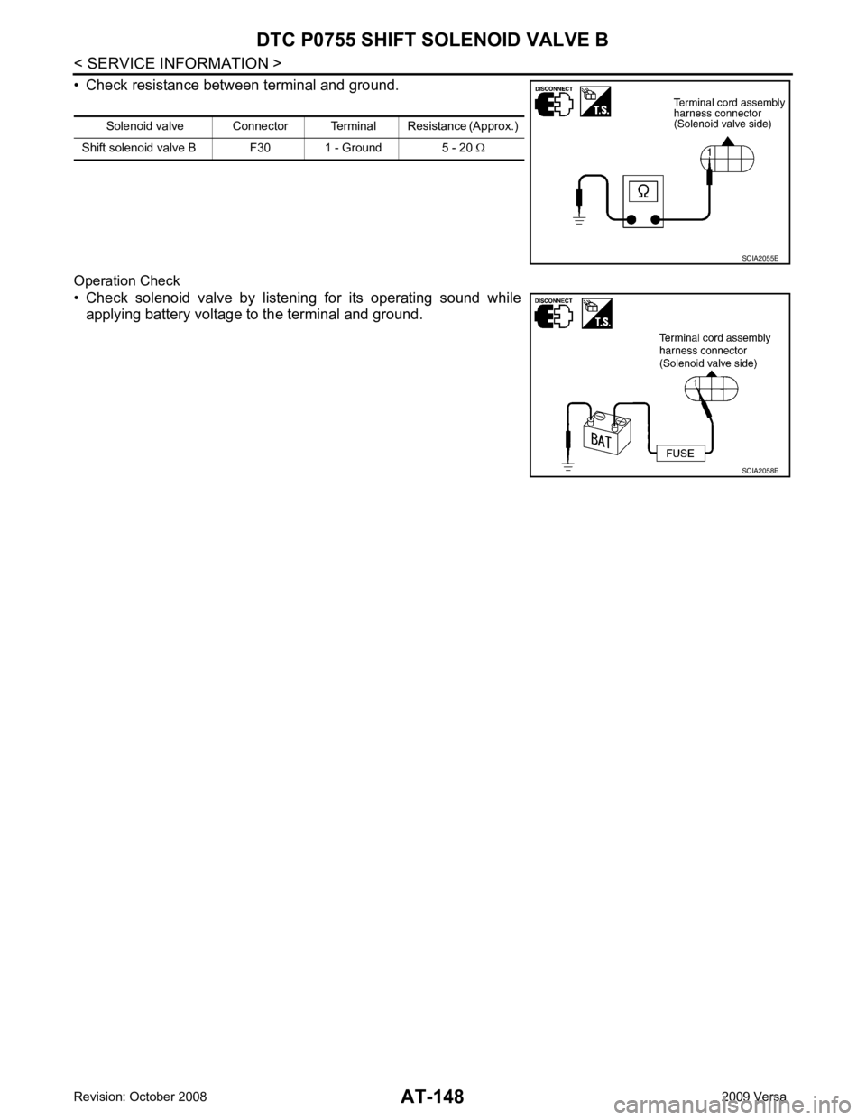
• Check resistance between terminal and ground.
Operation Check
• Check solenoid valve by listening for its operating sound while applying battery voltage to the terminal and ground. Solenoid valve Connector Terminal Resistance (Approx.)
Shift solenoid valve B F30 1 - Ground 5 - 20 Ω SCIA2055E
SCIA2058E
Page 156 of 4331
AT
N
O P
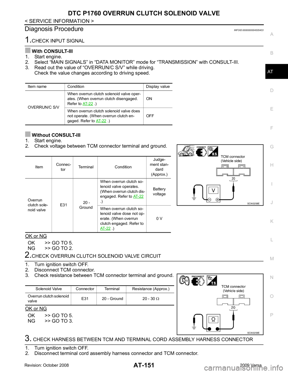
Diagnosis Procedure
INFOID:0000000004305433OK >> GO TO 5.
NG >> GO TO 2. OK >> GO TO 5.
NG >> GO TO 3. .)
ON
When overrun clutch solenoid valve does
not operate. (When overrun clutch en-
gaged. Refer to AT-22 .)
OFFItem
Connec-
tor Terminal Condition Judge-
ment stan- dard
(Approx.)
Overrun
clutch sole-
noid valve E31
20 -
Ground When overrun clutch so-
lenoid valve operates.
(When overrun clutch dis-
engaged. Refer to AT-22
.) Battery
voltage
When overrun clutch so-
lenoid valve dose not op-
erate. (When overrun
clutch engaged. Refer to
AT-22 .)
0 V
Page 157 of 4331
OK >> GO TO 4.
NG >> Repair open circuit or short to ground or short to power in harness or connectors. OK >> GO TO 5.
NG >> Repair or replace damaged parts. DTC Confirmation Procedure " .
OK or NG OK >>
INSPECTION END
NG >> GO TO 6. TCM Terminal and Reference Value " .
2. If NG, recheck TCM pin terminals for damage or loose connection with harness connector.
OK or NG OK >>
INSPECTION END
NG >> Repair or replace damaged parts.
Component Inspection INFOID:0000000004305434
OVERRUN CLUTCH SOLENOID VALVE
• For removal, refer to AT-221, " Control Valve Assembly and Accumulators " .
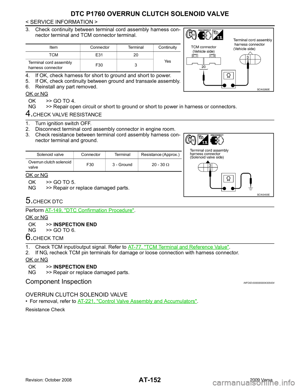
Resistance Check Item Connector Terminal Continuity
TCM E31 20 Yes
Terminal cord assembly
harness connector F30 3
Page 158 of 4331
AT
N
O P
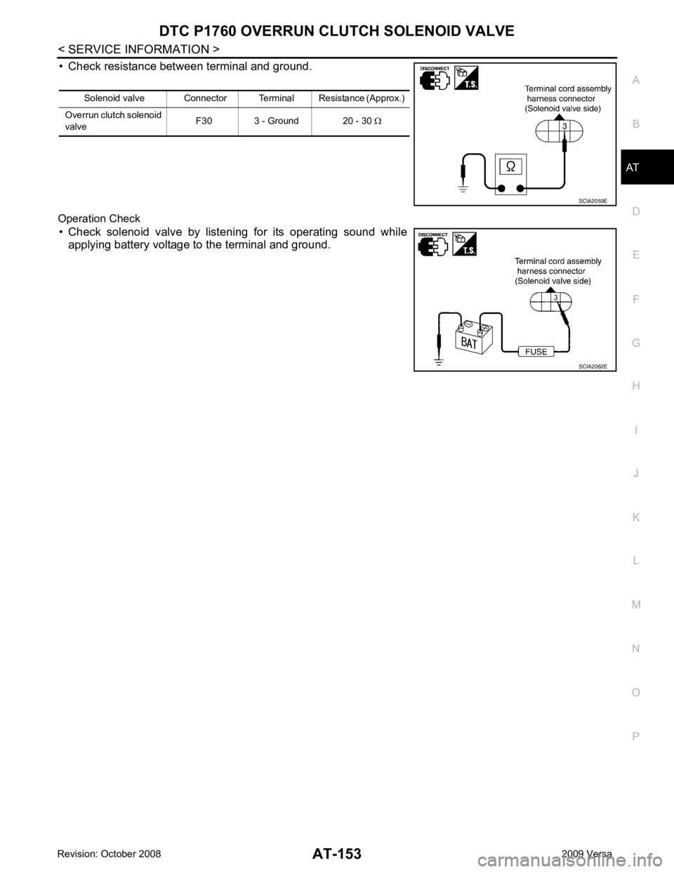
• Check resistance between terminal and ground.
Operation Check • Check solenoid valve by listening for its operating sound while applying battery voltage to the terminal and ground. Solenoid valve Connector Terminal Resistance (Approx.)
Overrun clutch solenoid
valve F30 3 - Ground 20 - 30
Ω
Page 161 of 4331
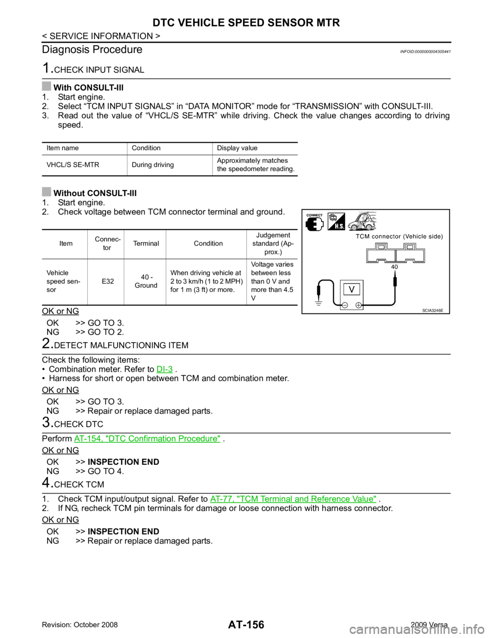
OK >> GO TO 3.
NG >> GO TO 2. .
• Harness for short or open between TCM and combination meter.
OK or NG OK >> GO TO 3.
NG >> Repair or replace damaged parts. DTC Confirmation Procedure " .
OK or NG OK >>
INSPECTION END
NG >> GO TO 4. TCM Terminal and Reference Value " .
2. If NG, recheck TCM pin terminals for damage or loose connection with harness connector.
OK or NG OK >>
INSPECTION END
NG >> Repair or replace damaged parts.
Item name Condition Display value
VHCL/S SE-MTR During driving Approximately matches
the speedometer reading. Item
Connec-
tor Terminal Condition Judgement
standard (Ap- prox.)
Vehicle
speed sen-
sor E32
40 -
Ground When driving vehicle at
2 to 3 km/h (1 to 2 MPH)
for 1 m (3 ft) or more. Voltage varies
between less
than 0 V and
more than 4.5
V
Page 165 of 4331
AT-160< SERVICE INFORMATION >
DTC BATT/FLUID TEMP SEN (A/T FLU
ID TEMP SENSOR CIRCUIT AND TCM
POWER SOURCE)
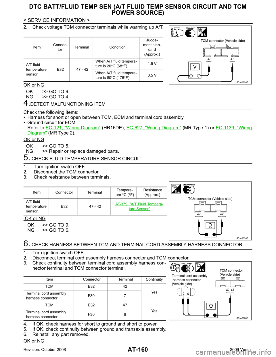
2. Check voltage TCM connector terminals while warming up A/T.
OK or NG OK >> GO TO 9.
NG >> GO TO 4. 4.
DETECT MALFUNCTIONING ITEM
Check the following items:
• Harness for short or open between TCM, ECM and terminal cord assembly
• Ground circuit for ECM
Refer to EC-121, " Wiring Diagram " (HR16DE),
EC-627, " Wiring Diagram " (MR Type 1) or
EC-1139, " Wiring
Diagram " (MR Type 2).
OK or NG OK >> GO TO 5.
NG >> Repair or replace damaged parts. 5.
CHECK FLUID TEMPERATURE SENSOR CIRCUIT
1. Turn ignition switch OFF.
2. Disconnect the TCM connector.
3. Check resistance between terminals.
OK or NG OK >> GO TO 9.
NG >> GO TO 6. 6.
CHECK HARNESS BETWEEN TCM AND TERM INAL CORD ASSEMBLY HARNESS CONNECTOR
1. Turn ignition switch OFF.
2. Disconnect terminal cord assembly harness connector and TCM connector.
3. Check continuity between terminal cord assembly harness con-
nector terminal and TCM connector terminal.
4. If OK, check harness for short to ground and short to power.
5. If OK, check continuity bet ween ground and transaxle assembly.
6. Reinstall any part removed.
OK or NG Item
Connec-
tor Terminal Condition Judge-
ment stan-
dard
(Approx.)
A/T fluid
temperature
sensor E32 47 - 42 When A/T fluid tempera-
ture is 20 °C (68 °F). 1.5 V
When A/T fluid tempera-
ture is 80 °C (176 °F). 0.5 V SCIA2658E
Item Connector Terminal
Tempera-
ture °C ( °F) Resistance
(Approx.)
A/T fluid
temperature
sensor E32 47 - 42
AT-379, " A/T Fluid Tempera-
ture Sensor "
SCIA2338E
Item Connector Terminal Continuity
TCM E32 42 Yes
Terminal cord assembly
harness connector F30 7
TCM E32 47 Yes
Terminal cord assembly
harness connector F30 6 SCIA2660E
Page 166 of 4331
DTC BATT/FLUID TEMP SEN (A/T FLU
ID TEMP SENSOR CIRCUIT AND TCM
POWER SOURCE)
AT-161
< SERVICE INFORMATION >
D
E
F
G H
I
J
K L
M A
B AT
N
O P
OK >> GO TO 7.
NG >> Repair open circuit or short to ground or short to power in harness or connectors. 7.
CHECK A/T FLUID TEMPERATURE SENSOR WITH TERMINAL CORD ASSEMBLY
1. Turn ignition switch OFF.
2. Disconnect terminal cord assembly connector in engine room.
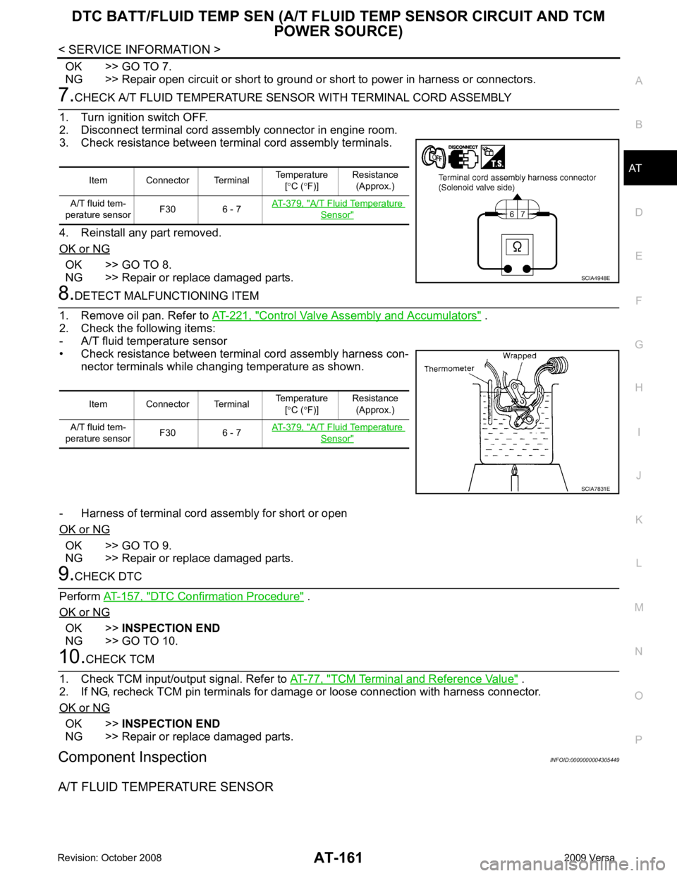
3. Check resistance between terminal cord assembly terminals.
4. Reinstall any part removed.
OK or NG OK >> GO TO 8.
NG >> Repair or replace damaged parts. 8.
DETECT MALFUNCTIONING ITEM
1. Remove oil pan. Refer to AT-221, " Control Valve Assembly and Accumulators " .
2. Check the following items:
- A/T fluid temperature sensor
• Check resistance between terminal cord assembly harness con- nector terminals while changing temperature as shown.
- Harness of terminal cord assembly for short or open
OK or NG OK >> GO TO 9.
NG >> Repair or replace damaged parts. 9.
CHECK DTC
Perform AT-157, " DTC Confirmation Procedure " .
OK or NG OK >>
INSPECTION END
NG >> GO TO 10. 10.
CHECK TCM
1. Check TCM input/output signal. Refer to AT-77, " TCM Terminal and Reference Value " .
2. If NG, recheck TCM pin terminals for dam age or loose connection with harness connector.
OK or NG OK >>
INSPECTION END
NG >> Repair or replace damaged parts.
Component Inspection INFOID:0000000004305449
A/T FLUID TEMPERATURE SENSOR Item Connector Terminal
Temperature
[° C ( °F)] Resistance
(Approx.)
A/T fluid tem-
perature sensor F30 6 - 7 AT-379, " A/T Fluid Temperature
Sensor "
SCIA4948E
Item Connector Terminal
Temperature
[° C ( °F)] Resistance
(Approx.)
A/T fluid tem-
perature sensor F30 6 - 7 AT-379, " A/T Fluid Temperature
Sensor "
SCIA7831E
Page 171 of 4331
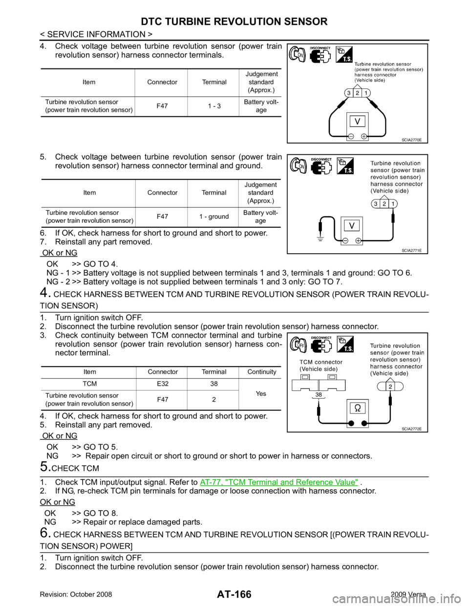
OK >> GO TO 4.
NG - 1 >> Battery voltage is not supplied betw een terminals 1 and 3, terminals 1 and ground: GO TO 6.
NG - 2 >> Battery voltage is not supp lied between terminals 1 and 3 only: GO TO 7.
4. CHECK HARNESS BETWEEN TCM AND TURBINE RE VOLUTION SENSOR (POWER TRAIN REVOLU- OK >> GO TO 5.
NG >> Repair open circuit or short to ground or short to power in harness or connectors. TCM Terminal and Reference Value " .
2. If NG, re-check TCM pin terminals for damage or loose connection with harness connector.
OK or NG OK >> GO TO 8.
NG >> Repair or replace damaged parts.
6. CHECK HARNESS BETWEEN TCM AND TURBINE REVOLUTION SENSOR [(POWER TRAIN REVOLU-
Page 172 of 4331
AT
N
O P
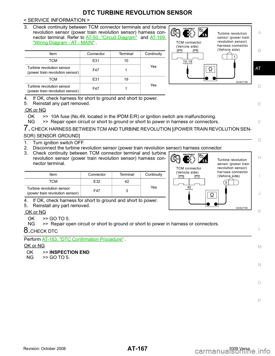
3. Check continuity between TCM connector terminals and turbine
revolution sensor (power train revolution sensor) harness con-
nector terminal. Refer to AT-50, " Circuit Diagram " and
AT-169, " Wiring Diagram - AT - MAIN " .
4. If OK, check harness for short to ground and short to power.
5. Reinstall any part removed.
OK or NG OK >> 10A fuse (No.49, located in the IPDM
E/R) or ignition switch are malfunctioning.
NG >> Repair open circuit or short to ground or short to power in harness or connectors.
7. CHECK HARNESS BETWEEN TCM AND TURBINE R EVOLUTION [(POWER TRAIN REVOLUTION SEN- OK >> GO TO 5.
NG >> Repair open circuit or short to ground or short to power in harness or connectors. DTC Confirmation Procedure " .
OK or NG OK >>
INSPECTION END
NG >> GO TO 5. Item Connector Terminal Continuity
TCM E31 10 Yes
Turbine revolu tion sensor
(power train revolution sensor) F47 1
TCM E31 19 Yes
Turbine revolu tion sensor
(power train revolution sensor) F47 1
Page 174 of 4331
AT
N
O P
MAIN POWER SUPPLY AND GROUND CIRCUIT
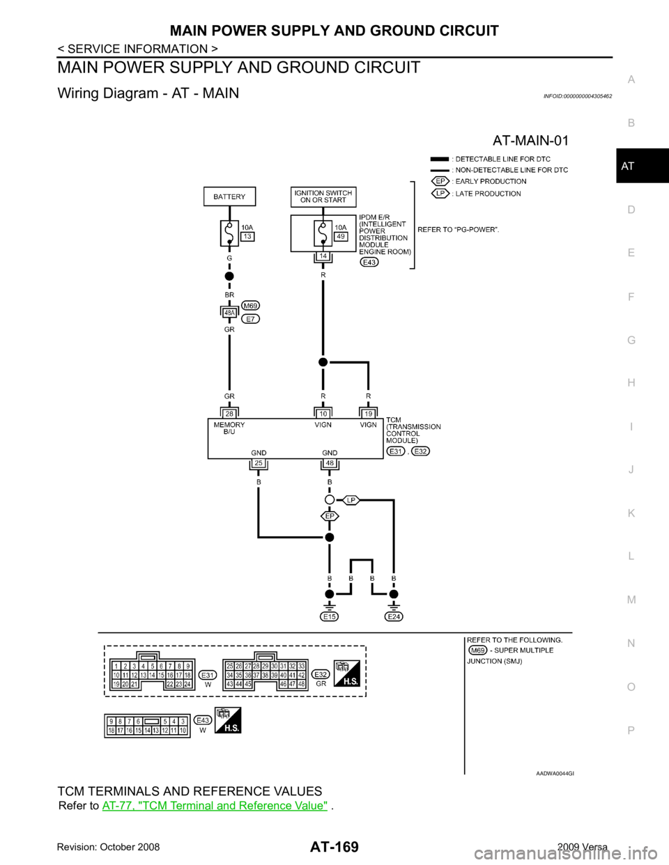
Wiring Diagram - AT - MAIN INFOID:0000000004305462
TCM TERMINALS AND REFERENCE VALUES Refer to AT-77, " TCM Terminal and Reference Value " . B