instrument panel NISSAN LATIO 2009 Service Owner's Manual
[x] Cancel search | Manufacturer: NISSAN, Model Year: 2009, Model line: LATIO, Model: NISSAN LATIO 2009Pages: 4331, PDF Size: 58.04 MB
Page 2407 of 4331
EC
NP
O
ON BOARD DIAGNOSTIC (OBD) SYSTEM
Introduction INFOID:0000000004499924
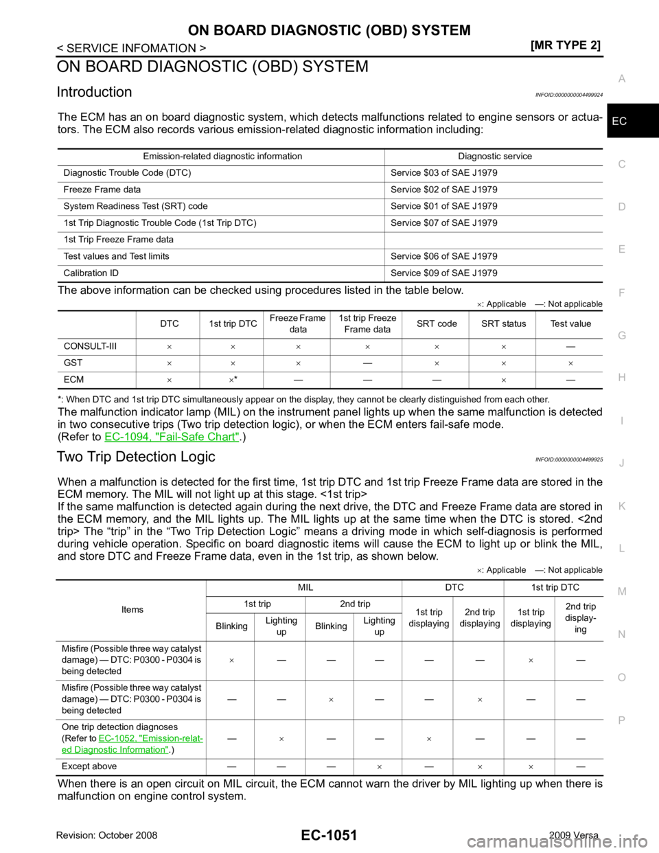
The ECM has an on board diagnostic system, which detects malfunctions related to engine sensors or actua-
tors. The ECM also records various emis sion-related diagnostic information including:
The above information can be checked using procedures listed in the table below. ×: Applicable —: Not applicable
*: When DTC and 1st trip DTC simultaneously appear on the display, they cannot be clearly distinguished from each other.
The malfunction indicator lamp (MIL) on the instrument panel lights up when the same malfunction is detected
in two consecutive trips (Two trip detection logic), or when the ECM enters fail-safe mode.
(Refer to EC-1094, " Fail-Safe Chart " .)
Two Trip Detection Logic INFOID:0000000004499925
When a malfunction is detected for the first time, 1st tr ip DTC and 1st trip Freeze Frame data are stored in the
ECM memory. The MIL will not light up at this stage. <1st trip>
If the same malfunction is detected again during the next drive, the DTC and Freeze Frame data are stored in
the ECM memory, and the MIL lights up. The MIL lights up at the same time when the DTC is stored. <2nd
trip> The “trip” in the “Two Trip Detection Logic” m eans a driving mode in which self-diagnosis is performed
during vehicle operation. Specific on board diagnostic item s will cause the ECM to light up or blink the MIL,
and store DTC and Freeze Frame data, even in the 1st trip, as shown below.
×: Applicable —: Not applicable
When there is an open circuit on MIL circuit, the ECM c annot warn the driver by MIL lighting up when there is
malfunction on engine control system. Emission-related diagnostic information Diagnostic service
Diagnostic Tr ouble Code (DTC) Service $03 of SAE J1979
Freeze Frame data Service $02 of SAE J1979
System Readiness Test (SRT) code Service $01 of SAE J1979
1st Trip Diagnostic Trou ble Code (1st Trip DTC) Service $07 of SAE J1979
1st Trip Freeze Frame data
Test values and Test limi ts Service $06 of SAE J1979
Calibration ID Servic e $09 of SAE J1979
DTC 1st trip DTC Freeze Frame
data 1st trip Freeze
Frame data SRT code SRT status Test value
CONSULT-III × × × × × × —
GST × × × —× × ×
ECM × ×* — — — ×— Items
MIL DTC 1st trip DTC
1st trip 2nd trip 1st trip
displaying 2nd trip
displaying 1st trip
displaying 2nd trip
display-
ing
Blinking Lighting
up Blinking
Lighting
up
Misfire (Possible three way catalyst
damage) — DTC: P0300 - P0304 is
being detected ×
— — — — — ×—
Misfire (Possible three way catalyst
damage) — DTC: P0300 - P0304 is
being detected — —
×— — ×— —
One trip detection diagnoses
(Refer to EC-1052, " Emission-relat-
ed Diagnostic Information " .)
—
×— — ×— — —
Except above — — — ×— × × —
Page 2425 of 4331
![NISSAN LATIO 2009 Service Owners Manual ON BOARD DIAGNOSTIC (OBD) SYSTEM
EC-1069
< SERVICE INFOMATION >
[MR TYPE 2] C
D E
F
G H
I
J
K L
M A EC
NP
O
4. Touch "ERASE". (The DTC in the ECM will be erased.)
With GST
NOTE:
If the ignition switc](/img/5/57359/w960_57359-2424.png "NISSAN LATIO 2009 Service Owners Manual ON BOARD DIAGNOSTIC (OBD) SYSTEM
EC-1069
< SERVICE INFOMATION >
[MR TYPE 2] C
D E
F
G H
I
J
K L
M A EC
NP
O
4. Touch \"ERASE\". (The DTC in the ECM will be erased.)
With GST
NOTE:
If the ignition switc")
ON BOARD DIAGNOSTIC (OBD) SYSTEM
EC-1069
< SERVICE INFOMATION >
[MR TYPE 2] C
D E
F
G H
I
J
K L
M A EC
NP
O
4. Touch "ERASE". (The DTC in the ECM will be erased.)
With GST
NOTE:
If the ignition switch stays ON after repair work, be sure to turn ignition switch OFF once. Wait at least 10 sec-
onds and then turn it ON (engine stopped) again.
1. Select Service $04 with GST.
No Tools
NOTE:
If the ignition switch stays ON after repair work, be sure to turn ignition switch OFF once. Wait at least 10 sec-
onds and then turn it ON (engine stopped) again.
1. Erase DTC in ECM. Refer to How to Erase Diagnostic Test Mode II (Self-diagnostic Results).
• If the battery is disconnected, the emission-relate d diagnostic information will be lost within 24
hours.
• The following data are cleared when the ECM memory is erased.
- Diagnostic trouble codes
- 1st trip diagnostic trouble codes
- Freeze frame data
- 1st trip freeze frame data
- System readiness test (SRT) codes
- Test values
Malfunction Indicator Lamp (MIL) INFOID:0000000004499927
DESCRIPTION The MIL is located on the instrument panel.
1. The MIL will light up when the ignition switch is turned ON with- out the engine running. This is a bulb check.
If the MIL does not light up, refer to DI-20 or see
EC-1532 .
2. When the engine is start ed, the MIL should go off.
If the MIL remains on, the on board diagnostic system has
detected an engine system malfunction.
ON BOARD DIAGNOSTIC SYSTEM FUNCTION The on board diagnostic system has the following three functions. SEF217U
Page 2427 of 4331
![NISSAN LATIO 2009 Service Owners Manual ON BOARD DIAGNOSTIC (OBD) SYSTEM
EC-1071
< SERVICE INFOMATION >
[MR TYPE 2] C
D E
F
G H
I
J
K L
M A EC
NP
O
ECM has entered to Diagnostic Test Mode II (Self-diagnostic results).
How to Erase Diagnosti](/img/5/57359/w960_57359-2426.png "NISSAN LATIO 2009 Service Owners Manual ON BOARD DIAGNOSTIC (OBD) SYSTEM
EC-1071
< SERVICE INFOMATION >
[MR TYPE 2] C
D E
F
G H
I
J
K L
M A EC
NP
O
ECM has entered to Diagnostic Test Mode II (Self-diagnostic results).
How to Erase Diagnosti")
ON BOARD DIAGNOSTIC (OBD) SYSTEM
EC-1071
< SERVICE INFOMATION >
[MR TYPE 2] C
D E
F
G H
I
J
K L
M A EC
NP
O
ECM has entered to Diagnostic Test Mode II (Self-diagnostic results).
How to Erase Diagnostic Test Mode II (Self-diagnostic Results) 1. Set ECM in Diagnostic Test Mode II (Self-diagnostic results). Refer to "How to Set Diagnostic Test Mode II (Self-diagnostic Results)".
2. Fully depress the accelerator pedal and keep it for more than 10 seconds. The emission-related diagnostic information has been erased from the backup memory in the ECM.
3. Fully release the accelerator pedal, and confirm the DTC 0000 is displayed.
DIAGNOSTIC TEST MODE I — BULB CHECK In this mode, the MIL on the instrument panel shoul d stay ON. If it remains OFF, check the bulb.
Refer to DI-20 or
EC-1532 .
DIAGNOSTIC TEST MODE I — MALFUNCTION WARNING
These DTC numbers are clarified in Diagnostic Test Mode II (SELF-DIAGNOSTIC RESULTS)
DIAGNOSTIC TEST MODE II — SELF-DIAGNOSTIC RESULTS In this mode, the DTC and 1st trip DTC are indicated by the number of blinks of the MIL as shown below.
The DTC and 1st trip DTC are displayed at the same time. If the MIL does not illuminate in diagnostic test
mode I (Malfunction warning), all displa yed items are 1st trip DTCs. If only one code is displayed when the MIL
illuminates in diagnostic test mode II (SELF-DIAGNOSTIC RESULTS), it is a DTC; if two or more codes are
displayed, they may be either DTCs or 1st trip DTCs. DTC No. is same as that of 1st trip DTC. These uniden- PBIB0092E
MIL Condition
ON When the malfunction is detected.
OFF No malfunction
Page 2898 of 4331
EI
N
O P
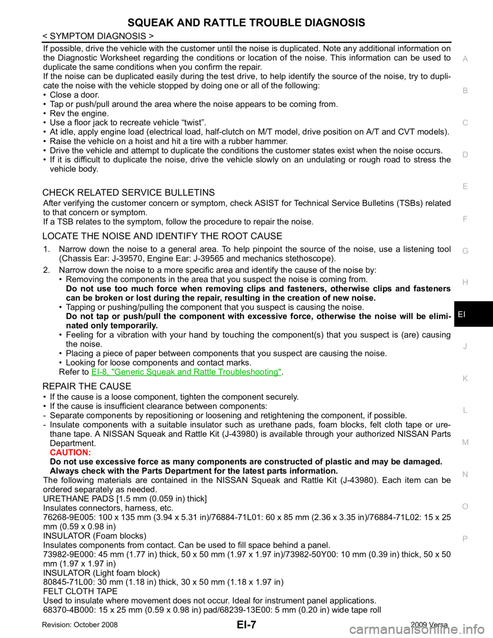
If possible, drive the vehicle with
the customer until the noise is duplicated. Note any additional information on
the Diagnostic Worksheet regarding the conditions or lo cation of the noise. This information can be used to
duplicate the same conditions when you confirm the repair.
If the noise can be duplicated easily during the test drive, to help identify the source of the noise, try to dupli-
cate the noise with the vehicle stopped by doing one or all of the following:
• Close a door.
• Tap or push/pull around the area where the noise appears to be coming from.
• Rev the engine.
• Use a floor jack to recreate vehicle “twist”.
• At idle, apply engine load (electrical load, half-clutch on M/T model, drive position on A/T and CVT models).
• Raise the vehicle on a hoist and hit a tire with a rubber hammer.
• Drive the vehicle and attempt to duplicate the conditions the customer states exist when the noise occurs.
• If it is difficult to duplicate the noise, drive the vehicle slowly on an undulating or rough road to stress the
vehicle body.
CHECK RELATED SERVICE BULLETINS After verifying the customer concern or symptom, che ck ASIST for Technical Service Bulletins (TSBs) related
to that concern or symptom.
If a TSB relates to the symptom, follow the procedure to repair the noise.
LOCATE THE NOISE AND IDENTIFY THE ROOT CAUSE 1. Narrow down the noise to a general area. To help pi npoint the source of the noise, use a listening tool
(Chassis Ear: J-39570, Engine Ear: J-39565 and mechanics stethoscope).
2. Narrow down the noise to a more specific area and identify the cause of the noise by: • Removing the components in the area that you suspect the noise is coming from.
Do not use too much force when removing clips and fasteners, otherwise clips and fasteners
can be broken or lost during the repair , resulting in the creation of new noise.
• Tapping or pushing/pulling the component that you suspect is causing the noise.
Do not tap or push/pull the component with excessi ve force, otherwise the noise will be elimi-
nated only temporarily.
• Feeling for a vibration with your hand by touching t he component(s) that you suspect is (are) causing
the noise.
• Placing a piece of paper between components that you suspect are causing the noise.
• Looking for loose components and contact marks.
Refer to EI-8, " Generic Squeak and Rattle Troubleshooting " .
REPAIR THE CAUSE • If the cause is a loose component, tighten the component securely.
• If the cause is insufficient clearance between components:
- Separate components by repositioning or loosening and retightening the component, if possible.
- Insulate components with a suitable insulator such as urethane pads, foam blocks, felt cloth tape or ure- thane tape. A NISSAN Squeak and Rattle Kit (J-43980) is available through your authorized NISSAN Parts
Department.
CAUTION:
Do not use excessive force as many components are constructed of plastic and may be damaged.
Always check with the Parts Department for the latest parts information.
The following materials are contained in the NISSA N Squeak and Rattle Kit (J-43980). Each item can be
ordered separately as needed.
URETHANE PADS [1.5 mm (0.059 in) thick]
Insulates connectors, harness, etc.
76268-9E005: 100 x 135 mm (3.94 x 5.31 in)/76884-71L01: 60 x 85 mm (2.36 x 3.35 in)/76884-71L02: 15 x 25
mm (0.59 x 0.98 in)
INSULATOR (Foam blocks)
Insulates components from contact. Can be used to fill space behind a panel.
73982-9E000: 45 mm (1.77 in) thick, 50 x 50 mm (1.97 x 1.97 in)/73982-50Y00: 10 mm (0.39 in) thick, 50 x 50
mm (1.97 x 1.97 in)
INSULATOR (Light foam block)
80845-71L00: 30 mm (1.18 in) thick, 30 x 50 mm (1.18 x 1.97 in)
FELT CLOTH TAPE
Used to insulate where movement does not occur. Ideal for instrument panel applications.
68370-4B000: 15 x 25 mm (0.59 x 0.98 in) pad/ 68239-13E00: 5 mm (0.20 in) wide tape roll
Page 3310 of 4331
GW
N
O P
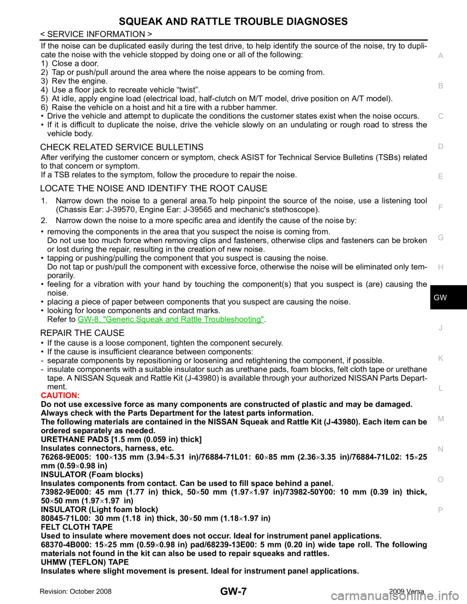
If the noise can be duplicated easily during the test drive,
to help identify the source of the noise, try to dupli-
cate the noise with the vehicle stopped by doing one or all of the following:
1) Close a door.
2) Tap or push/pull around the area where the noise appears to be coming from.
3) Rev the engine.
4) Use a floor jack to recreate vehicle “twist”.
5) At idle, apply engine load (electrical load, half- clutch on M/T model, drive position on A/T model).
6) Raise the vehicle on a hoist and hit a tire with a rubber hammer.
• Drive the vehicle and attempt to duplicate the conditions the customer states exist when the noise occurs.
• If it is difficult to duplicate the noise, drive the vehicle slowly on an undulating or rough road to stress the vehicle body.
CHECK RELATED SERVICE BULLETINS After verifying the customer concern or symptom, che ck ASIST for Technical Service Bulletins (TSBs) related
to that concern or symptom.
If a TSB relates to the symptom, follow the procedure to repair the noise.
LOCATE THE NOISE AND IDENTIFY THE ROOT CAUSE 1. Narrow down the noise to a general area.To help pinpoint the source of the noise, use a listening tool (Chassis Ear: J-39570, Engine Ear: J-39565 and mechanic's stethoscope).
2. Narrow down the noise to a more specific area and identify the cause of the noise by:
• removing the components in the area that you suspect the noise is coming from. Do not use too much force when removing clips and fasteners, otherwise clips and fasteners can be broken
or lost during the repair, resulting in the creation of new noise.
• tapping or pushing/pulling the component that you suspect is causing the noise.
Do not tap or push/pull the component with excessive force, otherwise the noise will be eliminated only tem-
porarily.
• feeling for a vibration with your hand by touching the component(s) that you suspect is (are) causing the
noise.
• placing a piece of paper between components that you suspect are causing the noise.
• looking for loose components and contact marks. Refer to GW-8, " Generic Squeak and Rattle Troubleshooting " .
REPAIR THE CAUSE • If the cause is a loose component, tighten the component securely.
• If the cause is insufficient clearance between components:
- separate components by repositioning or loos ening and retightening the component, if possible.
- insulate components with a suitable insulator such as urethane pads, foam blocks, felt cloth tape or urethane tape. A NISSAN Squeak and Rattle Kit (J-43980) is av ailable through your authorized NISSAN Parts Depart-
ment.
CAUTION:
Do not use excessive force as many components are constructed of plastic and may be damaged.
Always check with the Parts Department for the latest parts information.
The following materials are contained in the NISS AN Squeak and Rattle Kit (J-43980). Each item can be
ordered separately as needed.
URETHANE PADS [1.5 mm (0.059 in) thick]
Insulates connectors, harness, etc.
76268-9E005: 100 ×135 mm (3.94 ×5.31 in)/76884-71L01: 60 ×85 mm (2.36 ×3.35 in)/76884-71L02: 15 ×25
mm (0.59 ×0.98 in)
INSULATOR (Foam blocks)
Insulates components from contact. Can be used to fill space behind a panel.
73982-9E000: 45 mm (1.77 in) thick, 50 ×50 mm (1.97 ×1.97 in)/73982-50Y00: 10 mm (0.39 in) thick,
50 ×50 mm (1.97 ×1.97 in)
INSULATOR (Light foam block)
80845-71L00: 30 mm (1.18 in) thick, 30 ×50 mm (1.18 ×1.97 in)
FELT CLOTH TAPE
Used to insulate where movement does not occu r. Ideal for instrument panel applications.
68370-4B000: 15 ×25 mm (0.59 ×0.98 in) pad/68239-13E00: 5 mm (0.20 in) wide tape roll. The following
materials not found in the kit can also be used to repair squeaks and rattles.
UHMW (TEFLON) TAPE
Insulates where slight movement is present. Ideal for instrument panel applications.
Page 3317 of 4331

Removal and Installation " .
2. Remove the instrument side panel. Refer to IP-11 .
3. Apply protective tape around the opera window glas s to protect the painted surface from damage.
• If a opera window glass is to be reused, mark the body and the glass with mating marks.
4. Remove the opera window glass using piano wire or power cutting tool and inflatable pump bag.
WARNING:
When cutting the glass from the vehicle, always wear safety glasses and heavy gloves to help prevent
glass splinters from entering your eyes or cutting your hands.
CAUTION:
• When a opera window glass is to be reused, do not use a cutting knife or power cutting tool.
• Be careful not to scratch the glass when removing.
• Do not set or stand the glass on its edge. Small chips may develop into cracks.
• Clips are molded to the side window glass. Re place the clips with new ones if they are damaged
when removing the side window glass.
INSTALLATION
• Use a genuine NISSAN Urethane Adhesive Kit (if available) or equivalent and follow the instructions fur- nished with it.
• While the urethane adhesive is curing, open a door window . This will prevent the glass from being forced out
by passenger room air pressure when a door is closed.
• The opera window glass must be installed securely so that the molding around glass is in position and
leaves no gap.
Page 3371 of 4331

IP
N
O P
CONTENTS
INSTRUMENT PANEL
PRECAUTION ....... ........................................2
PRECAUTIONS .............................................. .....2
Precaution for Supplemental Restraint System
(SRS) "AIR BAG" and "SEAT BELT PRE-TEN-
SIONER" ............................................................. ......
2
Precaution Necessary fo r Steering Wheel Rota-
tion After Battery Disconnect ............................... ......
2
Precaution ........................................................... ......2
PREPARATION .... ........................................4
PREPARATION .............................................. .....4
Special Service Tool ........................................... ......4
Commercial Service Tool .................................... ......4 SYMPTOM DIAGNOSIS ....
...........................5
SQUEAK AND RATTLE TROUBLE DIAG-
NOSES ............................................................... 5
Work Flow ............................................................ .....5
Generic Squeak and Rattle Troubleshooting ....... .....7
Diagnostic Worksheet .......................................... .....9
ON-VEHICLE REPAIR ..... ............................11
INSTRUMENT PANEL ASSEMBLY ................. 11
Component Parts ................................................. ....11
Removal and Installation ..................................... ....12
Disassembly and Assembly ................................. ....23
Page 3376 of 4331
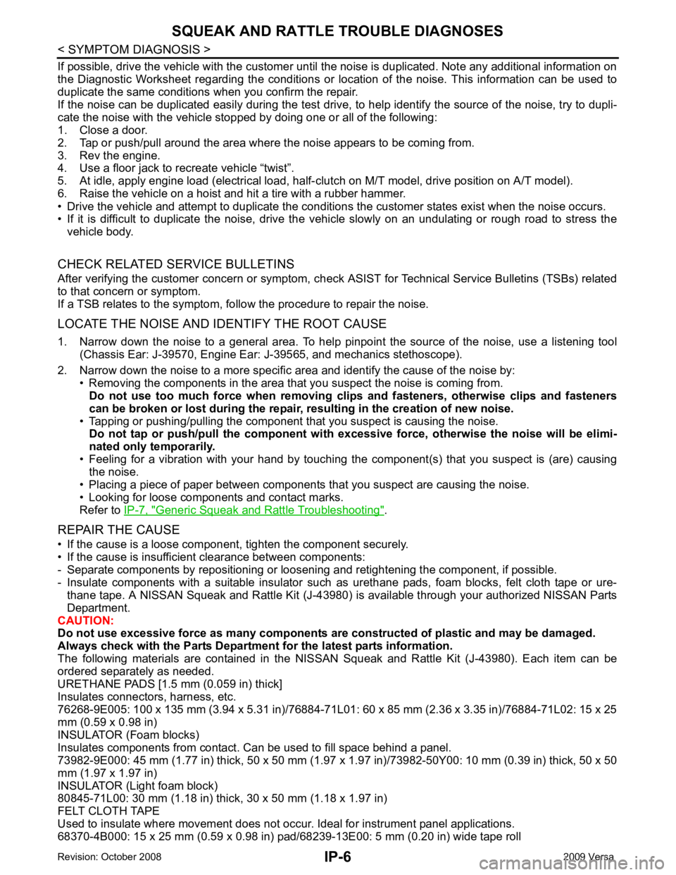
Generic Squeak and Rattle Troubleshooting " .
REPAIR THE CAUSE
• If the cause is a loose component, tighten the component securely.
• If the cause is insufficient clearance between components:
- Separate components by repositioning or loos ening and retightening the component, if possible.
- Insulate components with a suitable insulator such as urethane pads, foam blocks, felt cloth tape or ure-
thane tape. A NISSAN Squeak and Rattle Kit (J-43980) is available through your authorized NISSAN Parts
Department.
CAUTION:
Do not use excessive force as many components are constructed of plastic and may be damaged.
Always check with the Parts Department for the latest parts information.
The following materials are contained in the NISSAN Squeak and Rattle Kit (J-43980). Each item can be
ordered separately as needed.
URETHANE PADS [1.5 mm (0.059 in) thick]
Insulates connectors, harness, etc.
76268-9E005: 100 x 135 mm (3.94 x 5.31 in)/76884-71L01: 60 x 85 mm (2.36 x 3.35 in)/76884-71L02: 15 x 25
mm (0.59 x 0.98 in)
INSULATOR (Foam blocks)
Insulates components from contact. Can be used to fill space behind a panel.
73982-9E000: 45 mm (1.77 in) thick, 50 x 50 mm (1.97 x 1.97 in)/73982-50Y00: 10 mm (0.39 in) thick, 50 x 50
mm (1.97 x 1.97 in)
INSULATOR (Light foam block)
80845-71L00: 30 mm (1.18 in) thick, 30 x 50 mm (1.18 x 1.97 in)
FELT CLOTH TAPE
Used to insulate where movement does not occu r. Ideal for instrument panel applications.
68370-4B000: 15 x 25 mm (0.59 x 0.98 in) pad/68239-13E00: 5 mm (0.20 in) wide tape roll
Page 3377 of 4331
IP
N
O P
The following materials, not found in the kit, can also be used to repair squeaks and rattles.
UHMW (TEFLON) TAPE
Insulates where slight movement is present. Ideal for instrument panel applications.
SILICONE GREASE
Used in place of UHMW tape that will be visible or not fit.
Note: Will only last a few months.
SILICONE SPRAY
Use when grease cannot be applied.
DUCT TAPE
Use to eliminate movement.
CONFIRM THE REPAIR Confirm that the cause of a noise is repaired by test driving the vehicle. Operate the vehicle under the same
conditions as when the noise originally occurred. Refer to the notes on the Diagnostic Worksheet.
Generic Squeak and Rattle Troubleshooting INFOID:0000000004307245
Refer to Table of Contents for specific component removal and installation information.
INSTRUMENT PANEL Most incidents are caused by contact and movement between:
1. The cluster lid A and instrument panel
2. Acrylic lens and combination meter housing
3. Instrument panel to front pillar garnish
4. Instrument panel to windshield
5. Instrument panel mounting pins
6. Wiring harnesses behind the combination meter
7. A/C defroster duct and duct joint
These incidents can usually be located by tapping or moving the components to duplicate the noise or by
pressing on the components while driving to stop the noi se. Most of these incidents can be repaired by apply-
ing felt cloth tape or silicone spray (in hard to reach areas). Urethane pads can be used to insulate wiring har-
ness.
CAUTION:
Do not use silicone spray to isolate a squeak or ra ttle. If you saturate the area with silicone, you will
not be able to recheck the repair.
CENTER CONSOLE Components to pay attention to include:
1. Shifter assembly cover to finisher
2. A/C control unit and cluster lid C
3. Wiring harnesses behind audio and A/C control unit
The instrument panel repair and isolation pr ocedures also apply to the center console.
DOORS Pay attention to the:
1. Finisher and inner panel making a slapping noise
2. Inside handle escutcheon to door finisher
3. Wiring harnesses tapping
4. Door striker out of alignment causing a popping noise on starts and stops
Tapping or moving the components or pressing on them wh ile driving to duplicate the conditions can isolate
many of these incidents. You can usually insulate the ar eas with felt cloth tape or insulator foam blocks from
the NISSAN Squeak and Rattle Kit (J-43980) to repair the noise.
TRUNK Trunk noises are often caused by a loose jack or loose items put into the trunk by the owner.
In addition look for:
1. Trunk lid bumpers out of adjustment
2. Trunk lid striker out of adjustment
Page 3381 of 4331
IP
N
O P
ON-VEHICLE REPAIR
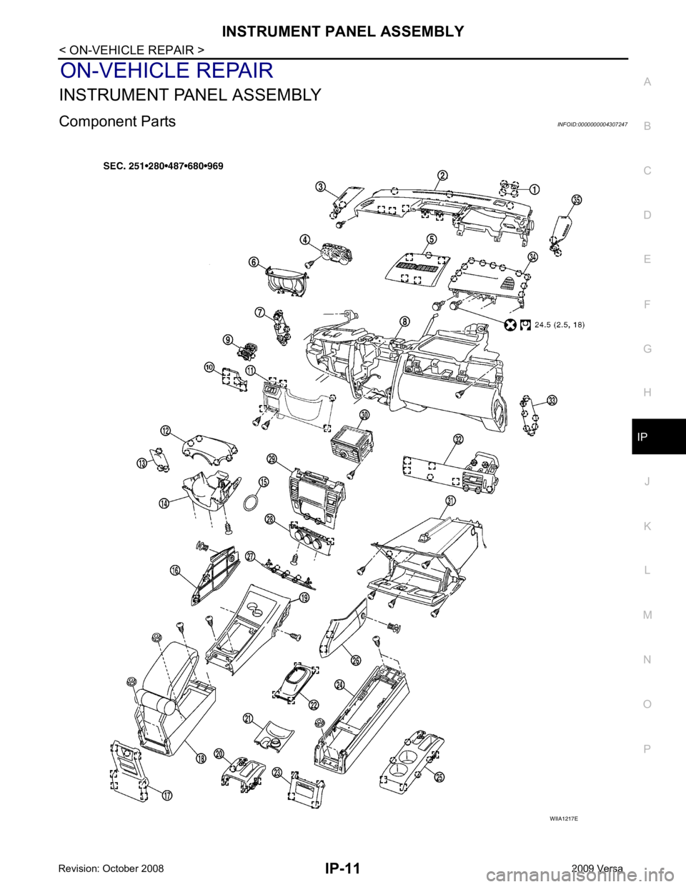
INSTRUMENT PANEL ASSEMBLY
Component Parts INFOID:0000000004307247