NISSAN LATIO 2009 Service Repair Manual
LATIO 2009
NISSAN
NISSAN
https://www.carmanualsonline.info/img/5/57359/w960_57359-0.png
NISSAN LATIO 2009 Service Repair Manual
Trending: sunroof, fuel filter location, fuel cap release, fuel cap, seats, child seat, steering wheel
Page 291 of 4331
AT-286< SERVICE INFORMATION >
REPAIR FOR COMPONENT PARTS
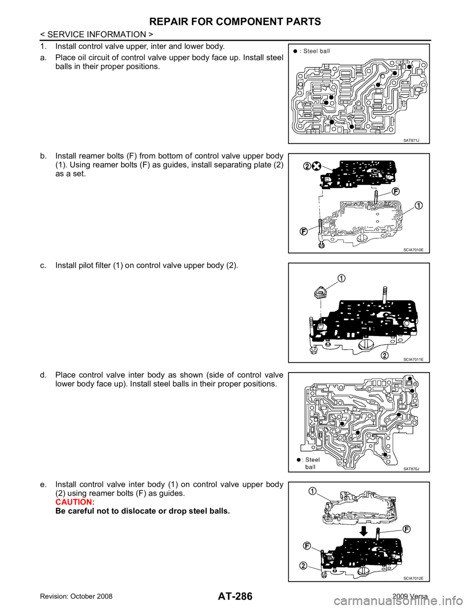
1. Install control valve upper, inter and lower body.
a. Place oil circuit of control valve upper body face up. Install steel balls in their proper positions.
b. Install reamer bolts (F) from bottom of control valve upper body (1). Using reamer bolts (F) as guides, install separating plate (2)
as a set.
c. Install pilot filter (1) on control valve upper body (2).
d. Place control valve inter body as shown (side of control valve lower body face up). Install steel balls in their proper positions.
e. Install control valve inter body (1) on control valve upper body (2) using reamer bolts (F) as guides.
CAUTION:
Be careful not to dislocate or drop steel balls. SAT871J
SCIA7010E
SCIA7011E
SAT870J
SCIA7012E
Page 292 of 4331
AT
N
O P
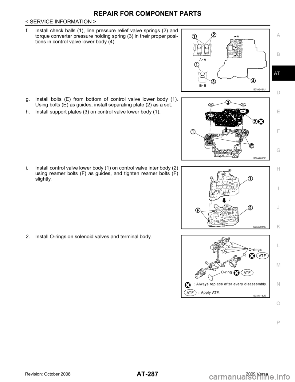
f. Install check balls (1), line pressure relief valve springs (2) and
torque converter pressure holding spring (3) in their proper posi-
tions in control valve lower body (4).
g. Install bolts (E) from bottom of control valve lower body (1). Using bolts (E) as guides, install separating plate (2) as a set.
h. Install support plates (3) on control valve lower body (1).
i. Install control valve lower body (1) on control valve inter body (2) using reamer bolts (F) as guides, and tighten reamer bolts (F)
slightly.
2. Install O-rings on solenoid valves and terminal body.
Page 293 of 4331
Page 294 of 4331
AT
N
O P
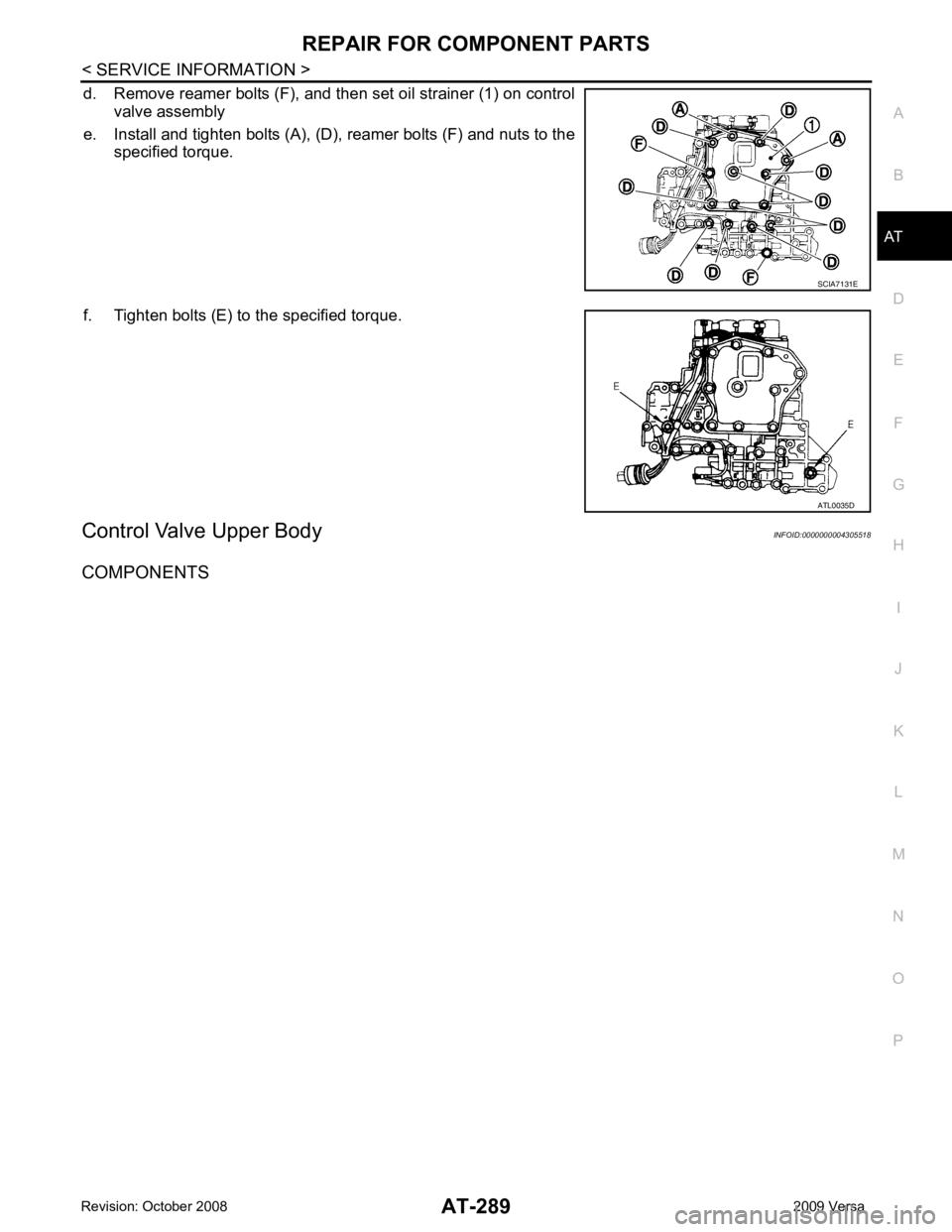
d. Remove reamer bolts (F), and then set oil strainer (1) on control
valve assembly
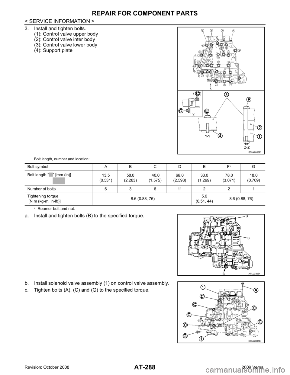
e. Install and tighten bolts (A), (D), reamer bolts (F) and nuts to the specified torque.
f. Tighten bolts (E) to the specified torque.
Control Valve Upper Body INFOID:0000000004305518
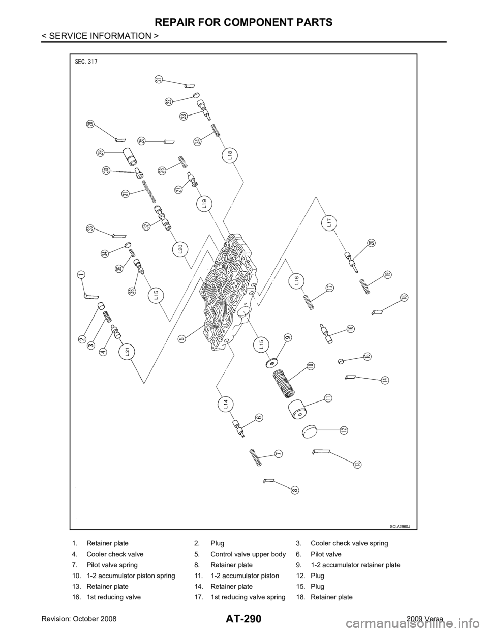
COMPONENTS
Page 295 of 4331
Page 296 of 4331
AT
N
O P
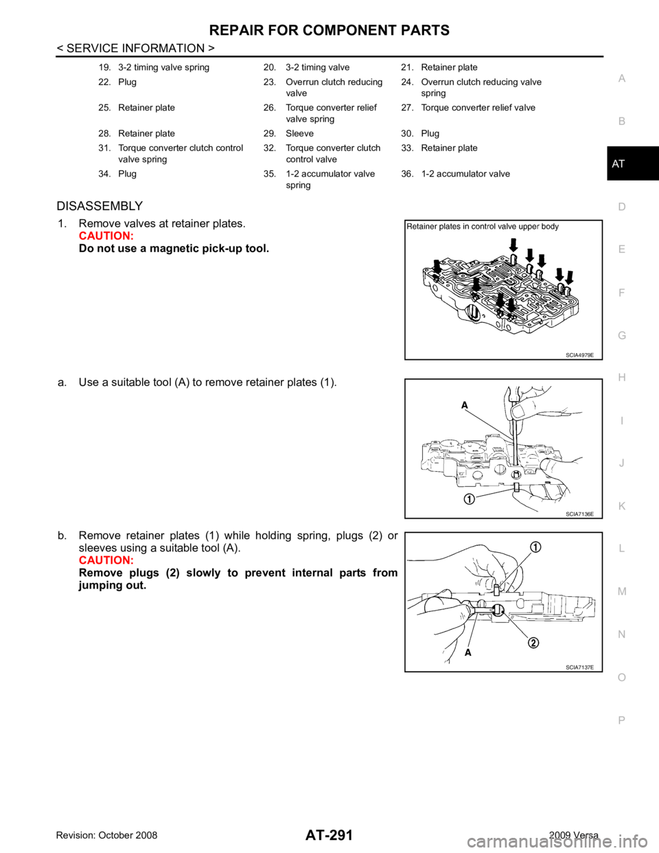
DISASSEMBLY
1. Remove valves at retainer plates. CAUTION:
Do not use a magnetic pick-up tool.
a. Use a suitable tool (A) to remove retainer plates (1).
b. Remove retainer plates (1) while holding spring, plugs (2) or sleeves using a suitable tool (A).
CAUTION:
Remove plugs (2) slowly to prevent internal parts from
jumping out. 19. 3-2 timing valve spring 20. 3-2 timing valve 21. Retainer plate
22. Plug 23. Overrun clutch reducing valve24. Overrun clutch reducing valve
spring
25. Retainer plate 26. Torque converter relief valve spring27. Torque converter relief valve
28. Retainer plate 29. Sleeve 30. Plug
31. Torque converter clutch control valve spring 32. Torque converter clutch
control valve 33. Retainer plate
34. Plug 35. 1-2 accumulator valve spring36. 1-2 accumulator valve
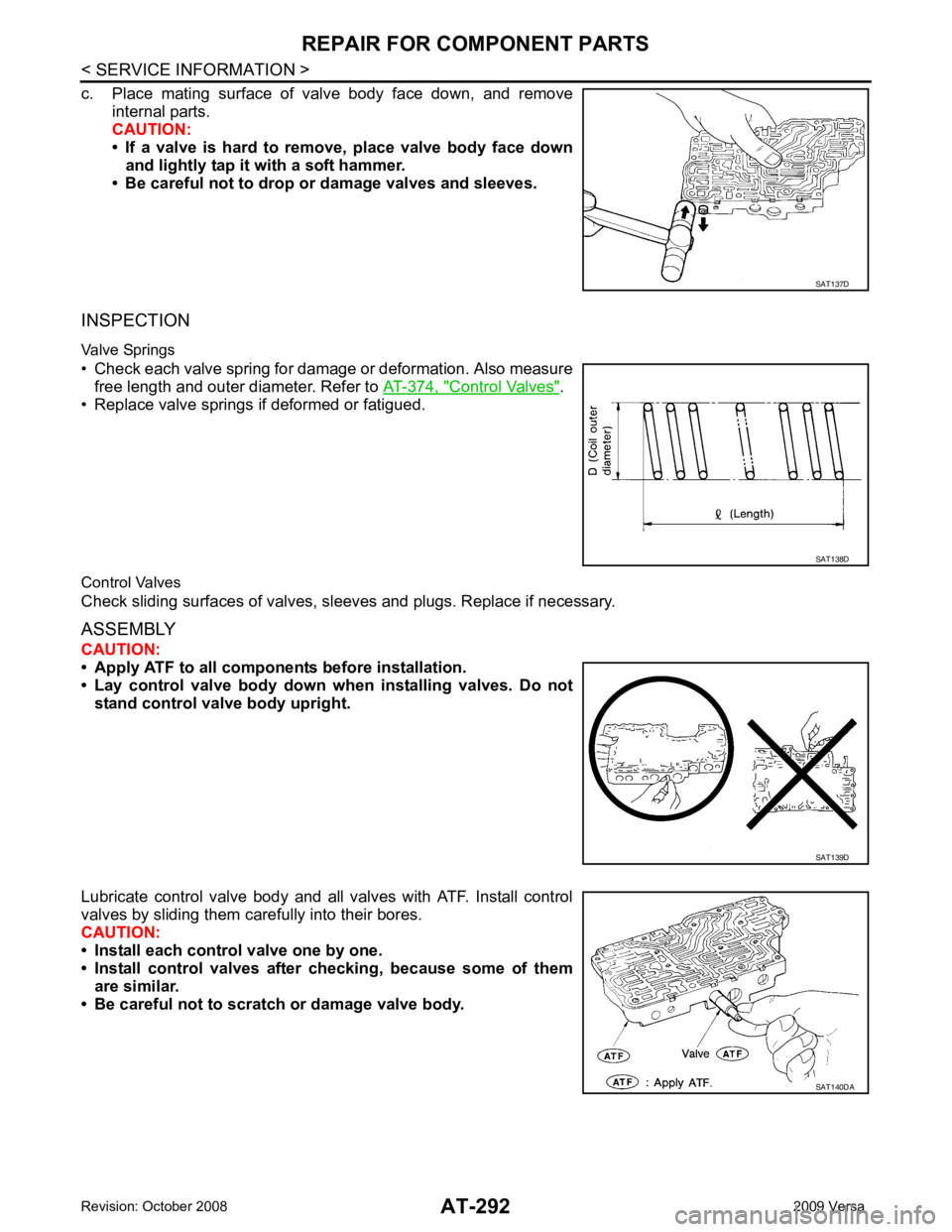
Page 297 of 4331
Control Valves " .
• Replace valve springs if deformed or fatigued.
Control Valves
Check sliding surfaces of valves, sl eeves and plugs. Replace if necessary.
ASSEMBLY
CAUTION:
• Apply ATF to all componen ts before installation.
• Lay control valve body down wh en installing valves. Do not
stand control valve body upright.
Lubricate control valve body and all valves with ATF. Install control
valves by sliding them carefully into their bores.
CAUTION:
• Install each control valve one by one.
• Install control valves after checking, because some of them
are similar.
• Be careful not to scratch or damage valve body. SAT138D
SAT140DA
Page 298 of 4331
AT
N
O P
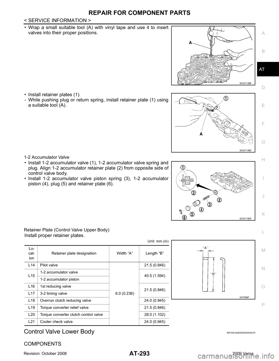
• Wrap a small suitable tool (A) with vinyl tape and use it to insert
valves into their proper positions.
• Install retainer plates (1).
- While pushing plug or return spring, install retainer plate (1) using a suitable tool (A).
1-2 Accumulator Valve • Install 1-2 accumulator valve (1), 1-2 accumulator valve spring and plug. Align 1-2 accumulator retainer plate (2) from opposite side of
control valve body.
• Install 1-2 accumulator valve piston spring (3), 1-2 accumulator
piston (4), plug (5) and retainer plate (6).
Retainer Plate (Control Valve Upper Body) Install proper retainer plates. Unit: mm (in)
Control Valve Lower Body INFOID:0000000004305519
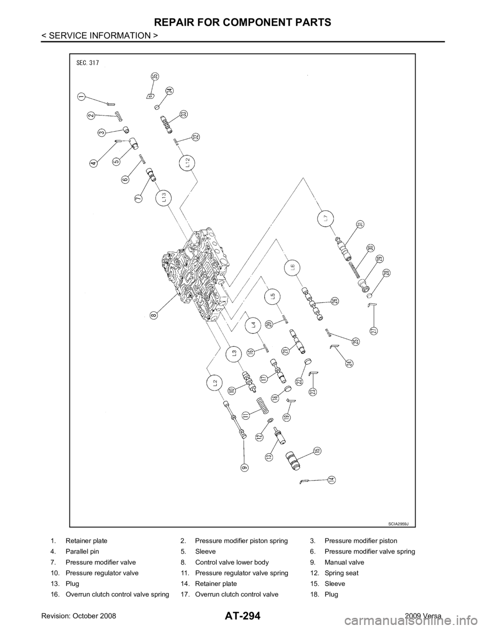
COMPONENTS
Page 299 of 4331
Page 300 of 4331
REPAIR FOR COMPONENT PARTS
AT-295
< SERVICE INFORMATION >
D
E
F
G H
I
J
K L
M A
B AT
N
O P
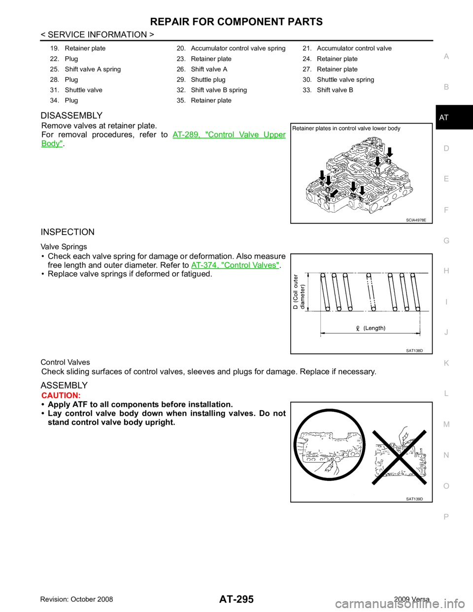
DISASSEMBLY
Remove valves at retainer plate.
For removal procedures, refer to AT-289, " Control Valve Upper
Body " .
INSPECTION
Valve Springs • Check each valve spring for damage or deformation. Also measure free length and outer diameter. Refer to AT-374, " Control Valves " .
• Replace valve springs if deformed or fatigued.
Control Valves Check sliding surfaces of control valves, sl eeves and plugs for damage. Replace if necessary.
ASSEMBLY CAUTION:
• Apply ATF to all componen ts before installation.
• Lay control valve body down wh en installing valves. Do not
stand control valve body upright. 19. Retainer plate 20. Accumulator control valve spring 21. Accumulator control valve
22. Plug 23. Retainer plate 24. Retainer plate
25. Shift valve A spring 26. Shift valve A 27. Retainer plate
28. Plug 29. Shuttle plug 30. Shuttle valve spring
31. Shuttle valve 32. Shift valve B spring 33. Shift valve B
34. Plug 35. Retainer plate SCIA4978E
SAT138D
SAT139D
Trending: tires, check engine, air condition, oil change, oil dipstick, coolant capacity, roof rack
