NISSAN LATIO 2009 Service Repair Manual
LATIO 2009
NISSAN
NISSAN
https://www.carmanualsonline.info/img/5/57359/w960_57359-0.png
NISSAN LATIO 2009 Service Repair Manual
Trending: steering, suspension, instrument cluster, service indicator, tow, fuel pump, radio
Page 3831 of 4331
MT
N
O P
MAINSHAFT AND GEAR
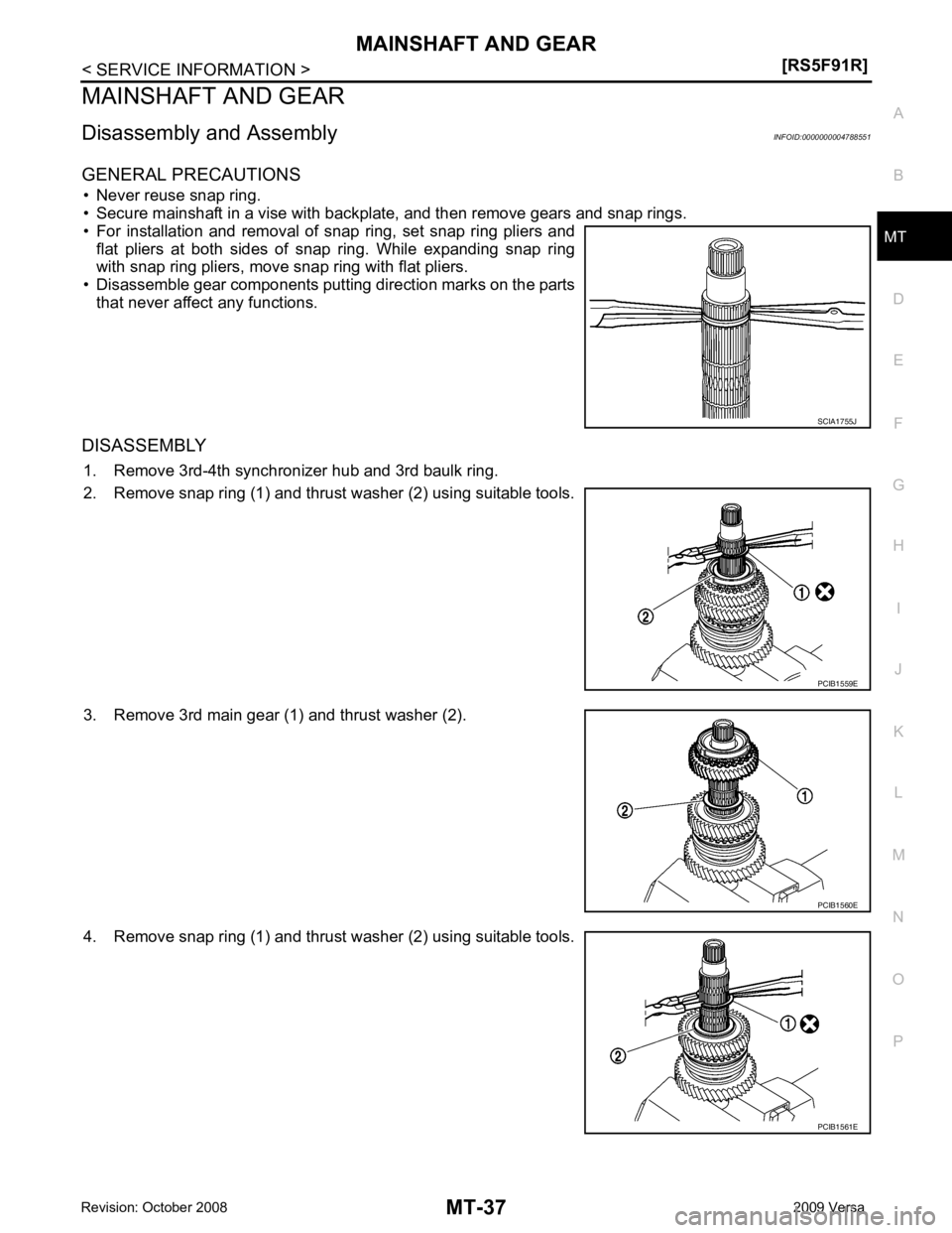
Disassembly and Assembly INFOID:0000000004788551
GENERAL PRECAUTIONS • Never reuse snap ring.
• Secure mainshaft in a vise with backplate, and then remove gears and snap rings.
• For installation and removal of snap ring, set snap ring pliers and flat pliers at both sides of snap ring. While expanding snap ring
with snap ring pliers, move snap ring with flat pliers.
• Disassemble gear components putting direction marks on the parts that never affect any functions.
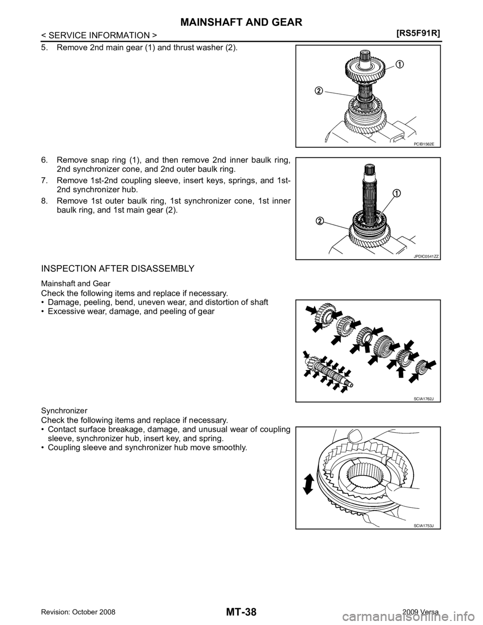
DISASSEMBLY 1. Remove 3rd-4th synchronizer hub and 3rd baulk ring.
2. Remove snap ring (1) and thrust washer (2) using suitable tools.
3. Remove 3rd main gear (1) and thrust washer (2).
4. Remove snap ring (1) and thrust washer (2) using suitable tools.
Page 3832 of 4331
Page 3833 of 4331
MT
N
O P
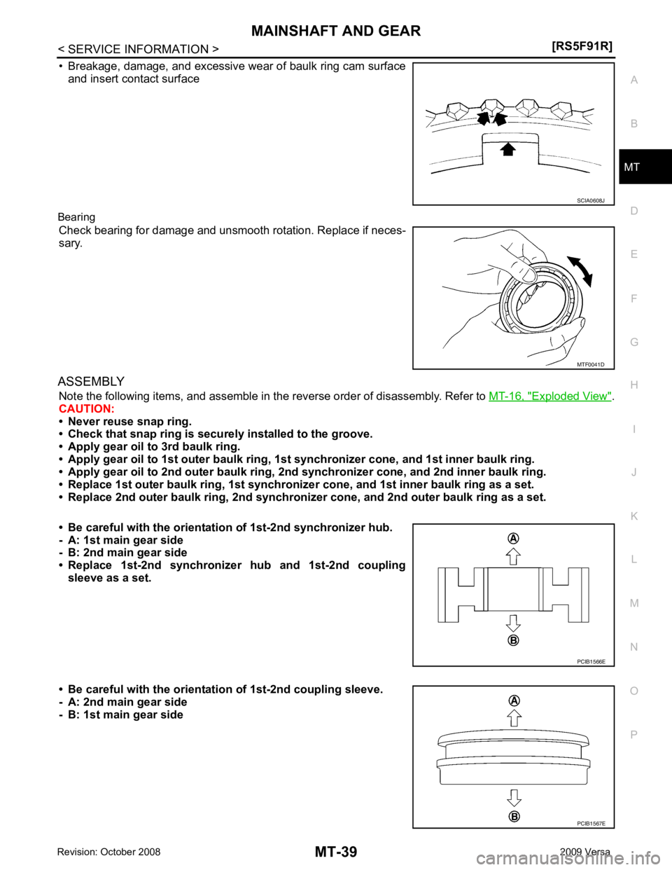
• Breakage, damage, and excessive wear of baulk ring cam surface
and insert contact surface
Bearing Check bearing for damage and unsmooth rotation. Replace if neces-
sary.
ASSEMBLY Note the following items, and assemble in t he reverse order of disassembly. Refer to MT-16, " Exploded View " .
CAUTION:
• Never reuse snap ring.
• Check that snap ring is secu rely installed to the groove.
• Apply gear oil to 3rd baulk ring.
• Apply gear oil to 1st outer baulk ring, 1st synchronizer cone, and 1st inner baulk ring.
• Apply gear oil to 2nd outer baulk ring, 2n d synchronizer cone, and 2nd inner baulk ring.
• Replace 1st outer baulk ring, 1st synchronize r cone, and 1st inner baulk ring as a set.
• Replace 2nd outer baulk ring, 2nd synchronize r cone, and 2nd outer baulk ring as a set.
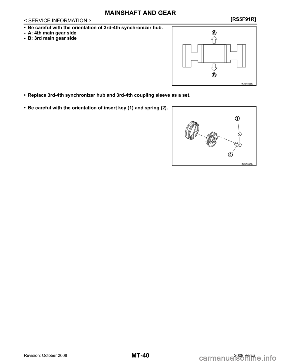
• Be careful with the orientation of 1st-2nd synchronizer hub.
- A: 1st main gear side
- B: 2nd main gear side
• Replace 1st-2nd synchronize r hub and 1st-2nd coupling
sleeve as a set.
• Be careful with the orientation of 1st-2nd coupling sleeve.
- A: 2nd main gear side
- B: 1st main gear side MTF0041D
Page 3834 of 4331
Page 3835 of 4331
FINAL DRIVE
MT-41
< SERVICE INFORMATION >
[RS5F91R] D
E
F
G H
I
J
K L
M A
B MT
N
O P
FINAL DRIVE
Disassembly and Assembly INFOID:0000000004788552
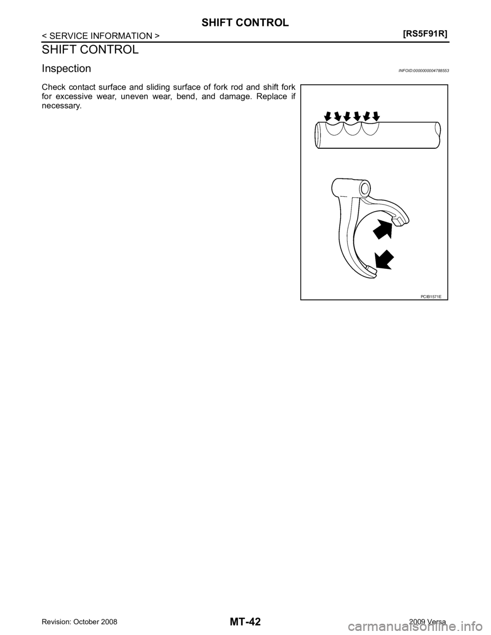
DISASSEMBLY 1. Remove differential side bearings using Tool (A) and a suitable tool.
2. Remove speedometer drive gear.
INSPECTION AFTER DISASSEMBLY
Case Check differential case and replace if necessary.
Bearing Check bearing for damage and unsmooth rotation. Replace if neces-
sary.
CAUTION:
Replace differential side bearing outer race and differential side
bearing as a set.
ASSEMBLY 1. Install speedometer drive gear.
2. Install differential side bearings using Tool (A).
CAUTION:
Replace differential side bearing outer race and differential
side bearing as a set. Tool number A: ST33052000 ( — ) PCIB1568E
SPD715
Tool number A: KV40104920 ( — )
PCIB1570E
Page 3836 of 4331
Page 3837 of 4331
MT
N
O P
SERVICE DATA AND SPECIFICATIONS (SDS)
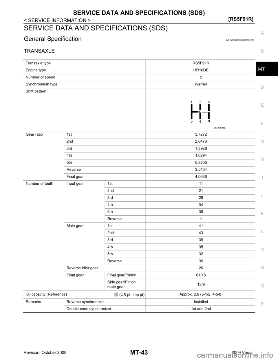
General Specification INFOID:0000000004784251
TRANSAXLE Transaxle type RS5F91R
Engine type HR16DE
Number of speed 5
Synchromesh type Warner
Shift pattern
Gear ratio 1st 3.7272
2nd 2.0476
3rd 1.3928
4th 1.0294
5th 0.8205
Reverse 3.5454
Final gear 4.0666
Number of teeth Input gear 1st 11 2nd 21
3rd 28
4th 34
5th 39
Reverse 11
Main gear 1st 41 2nd 43
3rd 39
4th 35
5th 32
Reverse 39
Reverse idler gear 26
Final gear Final gear/Pinion 61/15 Side gear/Pinion
mate gear 13/9
Oil capacity (Reference) (US pt, Imp pt)Approx. 2.6 (5-1/2, 4-5/8)
Remarks Reverse synchronizer Installed Double-cone synchronizer 1st and 2nd
Page 3838 of 4331
![NISSAN LATIO 2009 Service Repair Manual MT-44< SERVICE INFORMATION >
[RS6F94R]
PRECAUTIONS
SERVICE INFORMATION
PRECAUTIONS
Precaution for Supplemental Restraint Syst em (SRS) "AIR BAG" and "SEAT BELT
PRE-TENSIONER" INFOID:0000000004305264
NISSAN LATIO 2009 Service Repair Manual MT-44< SERVICE INFORMATION >
[RS6F94R]
PRECAUTIONS
SERVICE INFORMATION
PRECAUTIONS
Precaution for Supplemental Restraint Syst em (SRS) "AIR BAG" and "SEAT BELT
PRE-TENSIONER" INFOID:0000000004305264](/img/5/57359/w960_57359-3837.png)
MT-44< SERVICE INFORMATION >
[RS6F94R]
PRECAUTIONS
SERVICE INFORMATION
PRECAUTIONS
Precaution for Supplemental Restraint Syst em (SRS) "AIR BAG" and "SEAT BELT
PRE-TENSIONER" INFOID:0000000004305264
The Supplemental Restraint System such as “A IR BAG” and “SEAT BELT PRE-TENSIONER”, used along
with a front seat belt, helps to reduce the risk or severi ty of injury to the driver and front passenger for certain
types of collision. This system includes seat belt switch inputs and dual stage front air bag modules. The SRS
system uses the seat belt switches to determine the front air bag deployment, and may only deploy one front
air bag, depending on the severity of a collision and w hether the front occupants are belted or unbelted.
Information necessary to service the system safely is included in the SRS and SB section of this Service Man-
ual.
WARNING:
• To avoid rendering the SRS inopera tive, which could increase the risk of personal injury or death in
the event of a collision which would result in air bag inflation, all maintenance must be performed by
an authorized NISS AN/INFINITI dealer.
• Improper maintenance, including in correct removal and installation of the SRS, can lead to personal
injury caused by unintent ional activation of the system. For re moval of Spiral Cable and Air Bag
Module, see the SRS section.
• Do not use electrical test equipmen t on any circuit related to the SRS unless instructed to in this
Service Manual. SRS wiring harn esses can be identified by yellow and/or orange harnesses or har-
ness connectors.
Precaution for Procedure without Cowl Top Cover INFOID:0000000004305265
When performing the procedure after removing cowl top cover, cover
the lower end of windshield with urethane, etc.
Precaution INFOID:0000000004305266
• If transaxle assembly is removed from the vehi cle, always replace CSC (Concentric Slave Cylinder).
Installed CSC returns to the original position when removing transaxle assembly. Dust on clutch disc sliding
parts may damage CSC seal, and may cause clutch fluid leakage.
• Do not reuse transaxle oil.
• Drain, fill and check transaxle oil with the vehicle on level surface.
• During removal or installation, keep inside of transaxle clear of dust or dirt.
• Check for the correct installation orientation prior to removal or disassembly. If matching marks are required,
be certain they do not interfere with the f unction of the parts they are applied to.
• In principle, tighten bolts or nuts gradually in several steps working diagonally from inside to outside. If tight-
ening sequence is specified, follow it.
• Be careful not to damage the sliding surfaces and mating surfaces of parts. PIIB3706J
Page 3839 of 4331
MT
N
O P
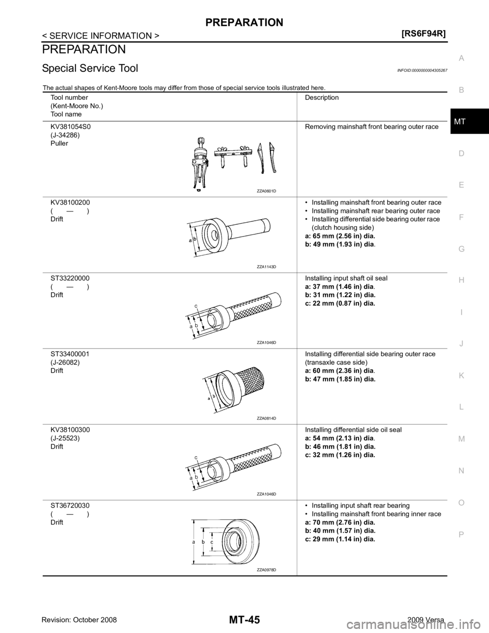
PREPARATION
Special Service Tool INFOID:0000000004305267
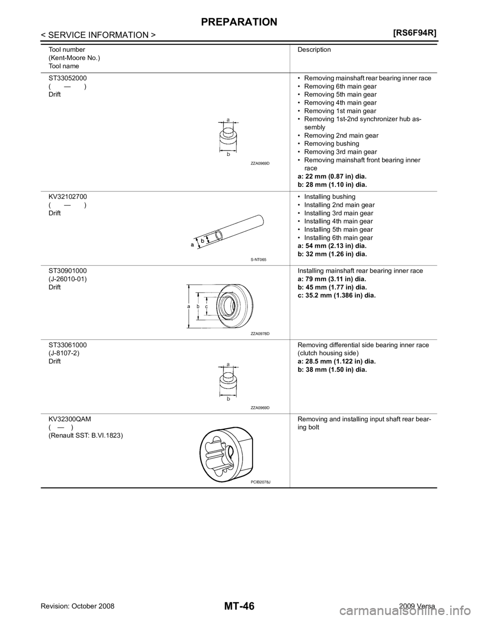
The actual shapes of Kent-Moore tools may differ fr om those of special service tools illustrated here.
Tool number
(Kent-Moore No.)
Tool name Description
KV381054S0
(J-34286)
Puller Removing mainshaft front bearing outer race
KV38100200
( — )
Drift • Installing mainshaft front bearing outer race
• Installing mainshaft rear bearing outer race
• Installing differential side bearing outer race
(clutch housing side)
a: 65 mm (2.56 in) dia.
b: 49 mm (1.93 in) dia .
ST33220000
( — )
Drift Installing input shaft oil seal
a: 37 mm (1.46 in) dia .
b: 31 mm (1.22 in) dia.
c: 22 mm (0.87 in) dia.
ST33400001
(J-26082)
Drift Installing differential side bearing outer race
(transaxle case side)
a: 60 mm (2.36 in) dia .
b: 47 mm (1.85 in) dia.
KV38100300
(J-25523)
Drift Installing differential side oil seal
a: 54 mm (2.13 in) dia .
b: 46 mm (1.81 in) dia.
c: 32 mm (1.26 in) dia.
ST36720030
( — )
Drift • Installing input shaft rear bearing
• Installing mainshaft front bearing inner race
a: 70 mm (2.76 in) dia.
b: 40 mm (1.57 in) dia.
c: 29 mm (1.14 in) dia. ZZA1143D
ZZA1046D
ZZA1046D
ZZA0978D
Page 3840 of 4331
S-NT065
ZZA0978D
PCIB2078J
Trending: wipers, keyless entry, spare wheel, fuel tank removal, engine overheat, lock, wheel bolt torque

![NISSAN LATIO 2009 Service Repair Manual FINAL DRIVE
MT-41
< SERVICE INFORMATION >
[RS5F91R] D
E
F
G H
I
J
K L
M A
B MT
N
O P
FINAL DRIVE
Disassembly and Assembly INFOID:0000000004788552
DISASSEMBLY 1. Remove differential side bearings u NISSAN LATIO 2009 Service Repair Manual FINAL DRIVE
MT-41
< SERVICE INFORMATION >
[RS5F91R] D
E
F
G H
I
J
K L
M A
B MT
N
O P
FINAL DRIVE
Disassembly and Assembly INFOID:0000000004788552
DISASSEMBLY 1. Remove differential side bearings u](/img/5/57359/w960_57359-3834.png)
![NISSAN LATIO 2009 Service Repair Manual MT-44< SERVICE INFORMATION >
[RS6F94R]
PRECAUTIONS
SERVICE INFORMATION
PRECAUTIONS
Precaution for Supplemental Restraint Syst em (SRS) "AIR BAG" and "SEAT BELT
PRE-TENSIONER" INFOID:0000000004305264
NISSAN LATIO 2009 Service Repair Manual MT-44< SERVICE INFORMATION >
[RS6F94R]
PRECAUTIONS
SERVICE INFORMATION
PRECAUTIONS
Precaution for Supplemental Restraint Syst em (SRS) "AIR BAG" and "SEAT BELT
PRE-TENSIONER" INFOID:0000000004305264](/img/5/57359/w960_57359-3837.png)

