air bleeding NISSAN LATIO 2009 Service Repair Manual
[x] Cancel search | Manufacturer: NISSAN, Model Year: 2009, Model line: LATIO, Model: NISSAN LATIO 2009Pages: 4331, PDF Size: 58.04 MB
Page 801 of 4331

BR
N
O P
CONTENTS
BRAKE SYSTEM
SERVICE INFORMATION .. ..........................2
PRECAUTIONS .............................................. .....2
Precaution for Supplemental Restraint System
(SRS) "AIR BAG" and "SEAT BELT PRE-TEN-
SIONER" ............................................................. ......
2
Precaution Necessary fo r Steering Wheel Rota-
tion After Battery Disconnect ............................... ......
2
Precaution for Brake System .............................. ......3
PREPARATION .............................................. .....4
Special Service Tool ........................................... ......4
Commercial Service Tool .................................... ......4
NOISE, VIBRATION AND HARSHNESS
(NVH) TROUBLESHOOTING ........................ .....5
NVH Troubleshooting Chart ................................ ......5
BRAKE PEDAL .............................................. .....6
Inspection and Adjustment .................................. ......6
Removal and Installation ...........................................7
BRAKE FLUID .....................................................9
On Board Inspection ........................................... ......9
Drain and Refill .................................................... ......9
Bleeding Brake System ....................................... ......9
BRAKE TUBE AND HOSE ............................ ....11
Hydraulic Circuit .................................................. ....11
Front Brake Tube and Hose ................................ ....12
Rear Brake Tube and Hose ................................ ....12
Inspection After Installation ................................. ....13
DUAL PROPORTIONING VALVE ................. ....14
Removal and Installation .........................................14
Inspection ............................................................ ....14
BRAKE MASTER CY LINDER ........................ ....15
On-Board Inspection ........................................... ....15 Removal and Installation .....................................
....15
Disassembly and Assembly ................................. ....16
BRAKE BOOSTER ........................................... 20
On Board Inspection ............................................ ....20
Removal and Installation ..................................... ....21
VACUUM LINES ............................................... 23
Component .......................................................... ....23
Removal and Installation ..................................... ....23
Inspection ............................................................ ....23
FRONT DISC BRAKE ....................................... 25
On Board Inspection ............................................ ....25
Component .......................................................... ....25
Removal and Installation of Brake Pad ...................26
Removal and Installation of Brake Caliper Assem-
bly ........................................................................ ....
28
Disassembly and Assembly of Brake Caliper As-
sembly ................................................................. ....
29
Brake Burnishing Procedure ................................ ....32
REAR DRUM B RAKE ....................................... 33
Component .......................................................... ....33
Removal and Installation of Drum Brake Assembly ....34
Removal and Installation of Wheel Cylinder ........ ....37
Disassembly and Assembly of Wheel Cylinder ... ....37
SERVICE DATA AND SPECIFICATIONS
(SDS) ................................................................. 38
General Specification .......................................... ....38
Brake Pedal ......................................................... ....39
Check Valve ........................................................ ....39
Brake Booster ...................................................... ....40
Front Disc Brake .................................................. ....40
Rear Drum Brake ................................................. ....40
Page 809 of 4331
BR
N
O P
BRAKE FLUID
On Board Inspection INFOID:0000000004305892
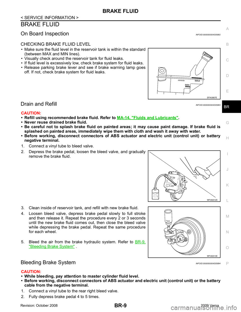
CHECKING BRAKE FLUID LEVEL • Make sure the fluid level in the reservoir tank is within the standard (between MAX and MIN lines).
• Visually check around the reservoir tank for fluid leaks.
• If fluid level is excessively low, check brake system for fluid leaks.
• Release parking brake lever and see if brake warning lamp goes
off. If not, check brake system for fluid leaks.
Drain and Refill INFOID:0000000004305893
CAUTION:
• Refill using recommended brake fluid. Refer to MA-14, " Fluids and Lubricants " .
• Never reuse drained brake fluid.
• Be careful not to splash brake fluid on painted areas; it may cause paint damage. If brake fluid is
splashed on painted areas, immediately wipe th em with cloth and wash it away with water.
• Before working, disconnect connect ors of ABS actuator and electric unit (control unit) or battery
negative terminal.
1. Connect a vinyl tube to bleed valve.
2. Depress the brake pedal, loosen the bleed valve, and gradually remove the brake fluid.
3. Clean inside of reservoir tank, and refill with new brake fluid.
4. Loosen bleed valve, depress brake pedal slowly to full stroke and then release it. Repeat the procedure every 2 or 3 seconds
until the new brake fluid comes out, then close the bleed valve
while depressing the brake pedal . Repeat the same procedure
for each wheel.
5. Bleed the air from the brake hydraulic system. Refer to BR-9," Bleeding Brake System " .
Bleeding Brake System INFOID:0000000004305894
CAUTION:
• While bleeding, pay attention to master cylinder fluid level.
• Before working, disconnect connectors of ABS actuator and electri c unit (control unit) or the battery
cable from the negative terminal.
1. Connect a vinyl tube to the rear right bleed valve.
2. Fully depress brake pedal 4 to 5 times.
Page 812 of 4331
Fluids and Lubricants " .
• Never reuse drained brake fluid.
Front Brake Tube and Hose INFOID:0000000004305896
REMOVAL
1. Drain brake fluid. Refer to BR-9, " Drain and Refill " .
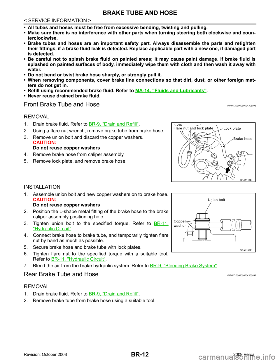
2. Using a flare nut wrench, remove brake tube from brake hose.
3. Remove union bolt and discard the copper washers. CAUTION:
Do not reuse copper washers
4. Remove brake hose from caliper assembly.
5. Remove lock plate, and remove brake hose.
INSTALLATION
1. Assemble union bolt and new copper washers on to brake hose. CAUTION:
Do not reuse copper washers
2. Position the L-shape metal fitting of the brake hose to the brake caliper assembly positioning hole.
3. Tighten union bolt to the specified torque. Refer to BR-11," Hydraulic Circuit " .
4. Connect brake hose to brake tube, and temporarily tighten flare nut by hand as much as possible.
5. Secure brake hose and brake tube with lock plates.
6. Tighten flare nut to the specified torque with a suitable tool. Refer to BR-11, " Hydraulic Circuit " .
7. Bleed the air from the brake hydraulic system. Refer to BR-9, " Bleeding Brake System " .
Rear Brake Tube and Hose INFOID:0000000004305897
REMOVAL
1. Drain brake fluid. Refer to BR-9, " Drain and Refill " .
2. Remove brake tube from brake hose using a suitable tool.
Page 813 of 4331
BR
N
O P
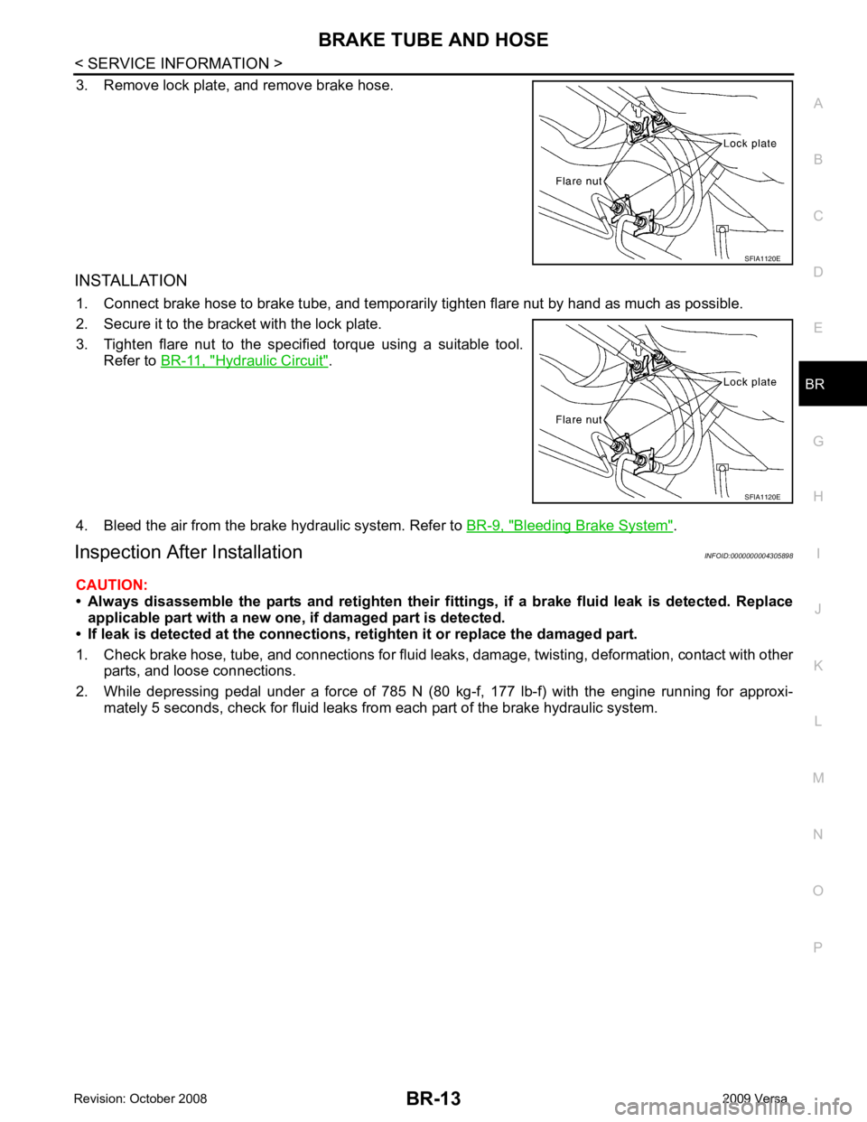
3. Remove lock plate, and remove brake hose.
INSTALLATION 1. Connect brake hose to brake tube, and temporaril y tighten flare nut by hand as much as possible.
2. Secure it to the bracket with the lock plate.
3. Tighten flare nut to the specified torque using a suitable tool. Refer to BR-11, " Hydraulic Circuit " .
4. Bleed the air from the brake hydraulic system. Refer to BR-9, " Bleeding Brake System " .
Inspection After Installation INFOID:0000000004305898
CAUTION:
• Always disassemble the parts and retighten their fitti ngs, if a brake fluid leak is detected. Replace
applicable part with a new one, if damaged part is detected.
• If leak is detected at the connections, retighten it or replace the damaged part.
1. Check brake hose, tube, and connections for fluid leak s, damage, twisting, deformation, contact with other
parts, and loose connections.
2. While depressing pedal under a force of 785 N (80 kg-f, 177 lb-f) with the engine running for approxi- mately 5 seconds, check for fluid leaks from each part of the brake hydraulic system. SFIA1120E
Page 814 of 4331
" Hydraulic Circuit " .
Inspection INFOID:0000000004305900
CAUTION:
• Carefully monitor brake flui d level at master cylinder.
• Use the recommended new brake fluid. Refer to MA-14, " Fluids and Lubricants " .
• Be careful not to splash brake fluid on painted areas; it may cause paint damage. If brake fluid is
splashed on paint areas, wash it away with water immediately.
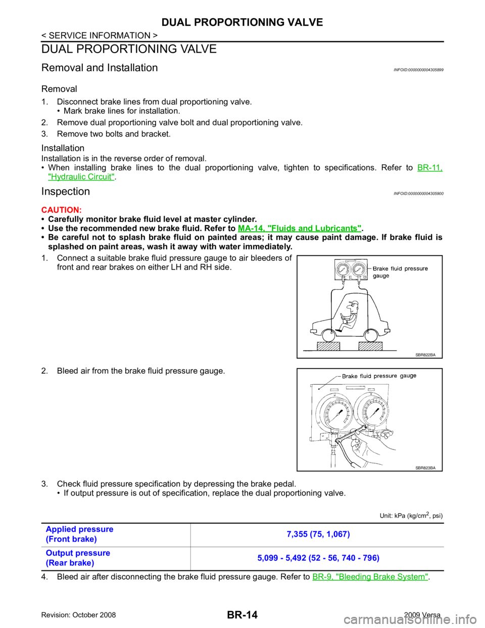
1. Connect a suitable brake fluid pressure gauge to air bleeders of front and rear brakes on either LH and RH side.
2. Bleed air from the brake fluid pressure gauge.
3. Check fluid pressure specific ation by depressing the brake pedal.
• If output pressure is out of specification, replace the dual proportioning valve.
Unit: kPa (kg/cm2
, psi)
4. Bleed air after disconnecting the brake fluid pressure gauge. Refer to BR-9, " Bleeding Brake System " .
Page 816 of 4331
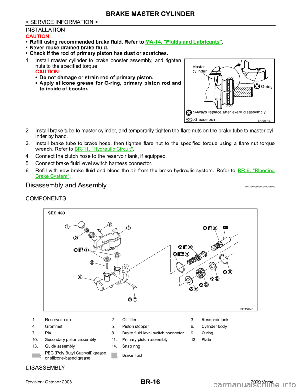
Fluids and Lubricants " .
• Never reuse drained brake fluid.
• Check if the rod of primary piston has dust or scratches.
1. Install master cylinder to brake booster assembly, and tighten nuts to the specified torque.
CAUTION:
• Do not damage or strain rod of primary piston.
• Apply silicone grease for O-ring, primary piston rod and to inside of booster.
2. Install brake tube to master cylinder, and temporarily tighten the flare nuts on the brake tube to master cyl-
inder by hand.
3. Install brake tube to brake hose, then tighten flare nut to the specified torque using a flare nut torque
wrench. Refer to BR-11, " Hydraulic Circuit " .
4. Connect the clutch hose to the reservoir tank, if equipped.
5. Connect brake fluid level switch harness connector.
6. Refill with new brake fluid and bleed the air from the brake hydraulic system. Refer toBR-9, " Bleeding
Brake System " .
Disassembly and Assembly INFOID:0000000004305903
COMPONENTS
DISASSEMBLY
Page 822 of 4331
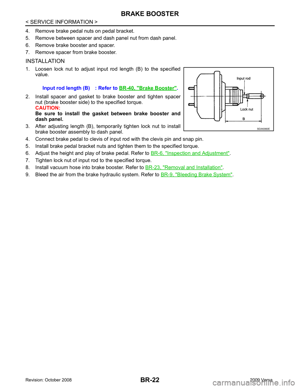
Inspection and Adjustment " .
7. Tighten lock nut of input rod to the specified torque.
8. Install vacuum hose into brake booster. Refer to BR-23, " Removal and Installation " .
9. Bleed the air from the brake hydraulic system. Refer to BR-9, " Bleeding Brake System " .
Input rod length (B) : Refer to
BR-40, " Brake Booster " .
Page 829 of 4331
BR
N
O P
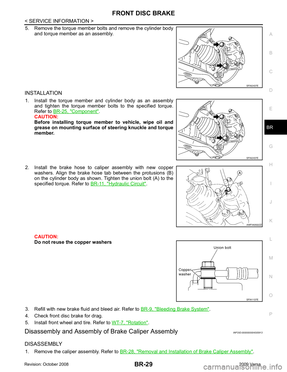
5. Remove the torque member bolts and remove the cylinder body
and torque member as an assembly.
INSTALLATION 1. Install the torque member and cylinder body as an assembly and tighten the torque member bolts to the specified torque.
Refer to BR-25, " Component " .
CAUTION:
Before installing torque member to vehicle, wipe oil and
grease on mounting surface of steering knuckle and torque
member.
2. Install the brake hose to caliper assembly with new copper washers. Align the brake hose tab between the protusions (B)
on the cylinder body as shown. Tighten the union bolt (A) to the
specified torque. Refer to BR-11, " Hydraulic Circuit " .
CAUTION:
Do not reuse the copper washers
3. Refill with new brake fluid and bleed air. Refer to BR-9, " Bleeding Brake System " .
4. Check front disc brake for drag.
5. Install front wheel and tire. Refer to WT-7, " Rotation " .
Disassembly and Assembly of Brake Caliper Assembly INFOID:0000000004305913
DISASSEMBLY 1. Remove the caliper assembly. Refer to BR-28, " Removal and Installation of Brake Caliper Assembly " .AWFIA0502ZZ
SFIA1137E
Page 837 of 4331
BR
N
O P
5. Connect the parking brake rear cable to the operating lever.
6. Install the shoe assembly. After assembly, be sure that each part is installed properly. CAUTION:
Do not damage the wheel cylinder piston boot.
7. Install the brake drum.
8. Depress brake pedal for several times (approximately 2 or 3 times).
9. Adjust clearance of brake shoe. Refer to PB-5, " On-Vehicle Service " .
10. Install rear wheel and tire. Refer to WT-7, " Rotation " .
Removal and Installati on of Wheel Cylinder INFOID:0000000004305917
REMOVAL 1. Drain the brake fluid. Refer to BR-9, " Drain and Refill " .
2. Remove the rear brake shoe assembly. Refer to BR-34, " Removal and Installation of Drum Brake Assem-
bly " .
3. Remove the bleed valve.
4. Disconnect the brake tube from the wheel cylinder.
5. Remove the wheel cylinder bolts and then remo ve the wheel cylinder from the back plate.
INSTALLATION Installation is in the reverse order of removal.
• Tighten bolts and bleed valve to the specified torque. Refer to BR-33, " Component " .
• Refill with new brake fluid and bleed the air. Refer to BR-9, " Bleeding Brake System " .
Disassembly and Assemb ly of Wheel Cylinder INFOID:0000000004305918
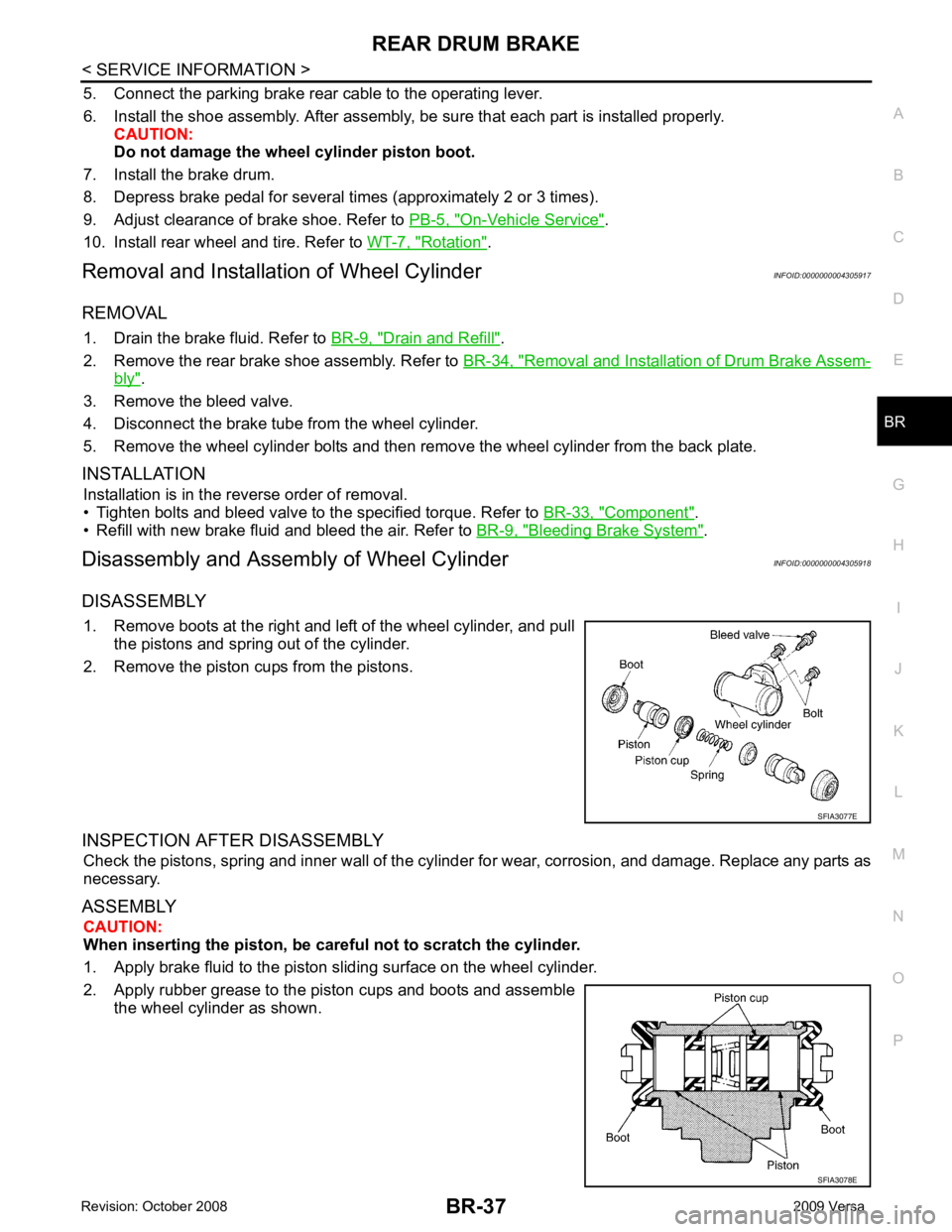
DISASSEMBLY 1. Remove boots at the right and left of the wheel cylinder, and pull the pistons and spring out of the cylinder.
2. Remove the piston cups from the pistons.
INSPECTION AFTER DISASSEMBLY Check the pistons, spring and inner wall of the cylinder for wear, corrosion, and damage. Replace any parts as
necessary.
ASSEMBLY CAUTION:
When inserting the piston, be caref ul not to scratch the cylinder.
1. Apply brake fluid to the piston sliding surface on the wheel cylinder.
2. Apply rubber grease to the piston cups and boots and assemble the wheel cylinder as shown.
Page 875 of 4331
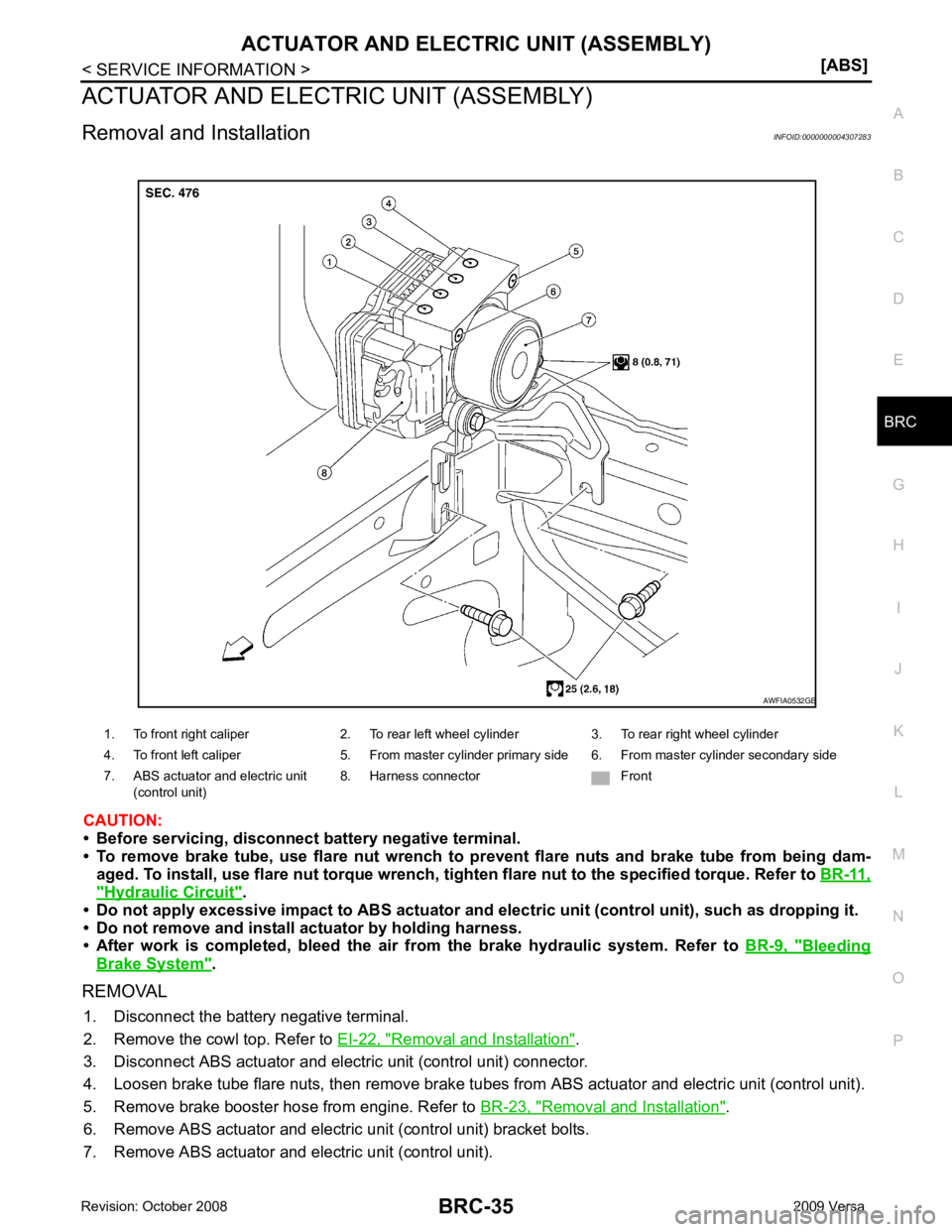
BRC
N
O P
ACTUATOR AND ELECTRIC UNIT (ASSEMBLY)
Removal and Installation INFOID:0000000004307283
CAUTION:
• Before servicing, disconnect battery negative terminal.
• To remove brake tube, use flare nut wrench to pr event flare nuts and brake tube from being dam-
aged. To install, use flare nut torque wrench, ti ghten flare nut to the specified torque. Refer to BR-11," Hydraulic Circuit " .
• Do not apply excessive impact to ABS actuator and elect ric unit (control unit), such as dropping it.
• Do not remove and install actuator by holding harness.
• After work is completed, bleed the air from the brake hydraulic system. Refer to BR-9, " Bleeding
Brake System " .
REMOVAL 1. Disconnect the battery negative terminal.
2. Remove the cowl top. Refer to EI-22, " Removal and Installation " .
3. Disconnect ABS actuator and electric unit (control unit) connector.
4. Loosen brake tube flare nuts, then remove brake tubes from ABS actuator and electric unit (control unit).
5. Remove brake booster hose from engine. Refer to BR-23, " Removal and Installation " .
6. Remove ABS actuator and electric unit (control unit) bracket bolts.
7. Remove ABS actuator and electric unit (control unit). 1. To front right caliper 2. To rear left wheel cylinder 3. To rear right wheel cylinder
4. To front left caliper 5. From master cylinder primary side 6. From master cylinder secondary side
7. ABS actuator and electric unit (control unit) 8. Harness connector Front