AT
N
O P
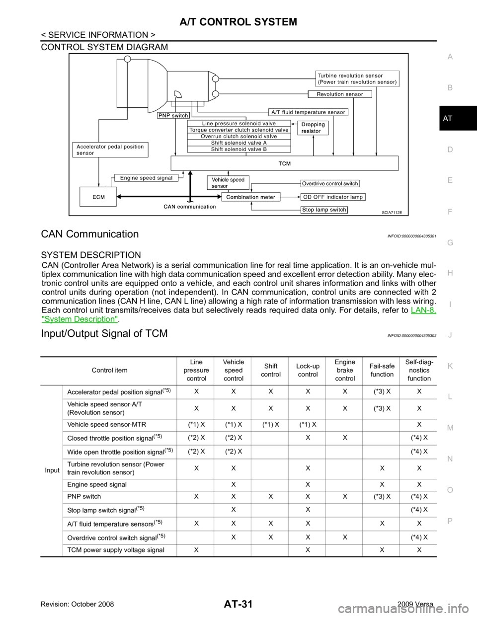
CONTROL SYSTEM DIAGRAM
CAN Communication INFOID:0000000004305301
SYSTEM DESCRIPTION CAN (Controller Area Network) is a serial communication li ne for real time application. It is an on-vehicle mul-
tiplex communication line with high data communication speed and excellent error detection ability. Many elec-
tronic control units are equipped onto a vehicle, and each control unit shares information and links with other
control units during operation (not independent). In CAN communication, control units are connected with 2
communication lines (CAN H line, CAN L line) allowing a high rate of information transmission with less wiring.
Each control unit transmits/receives data but selectively reads required data only. For details, refer to LAN-8," System Description " .
Input/Output Signal of TCM INFOID:0000000004305302
AT
N
O P
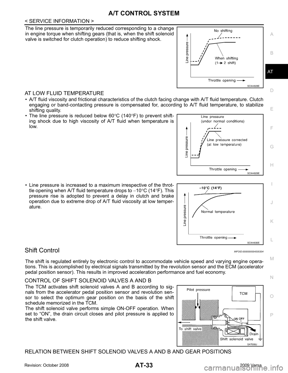
The line pressure is temporarily reduced corresponding to a change
in engine torque when shifting gears (that is, when the shift solenoid
valve is switched for clutch operation) to reduce shifting shock.
AT LOW FLUID TEMPERATURE • A/T fluid viscosity and frictional characteristics of t he clutch facing change with A/T fluid temperature. Clutch
engaging or band-contacting pressure is compensated for, according to A/T fluid temperature, to stabilize
shifting quality.
• The line pressure is reduced below 60 °C (140 °F) to prevent shift-
ing shock due to high viscosity of A/T fluid when temperature is
low.
• Line pressure is increased to a maximum irrespective of the throt- tle opening when A/T fluid temperature drops to −10 °C (14 °F). This
pressure rise is adopted to prevent a delay in clutch and brake
operation due to extreme drop of A/T fluid viscosity at low temper-
ature.
Shift Control INFOID:0000000004305304
The shift is regulated entirely by electronic cont rol to accommodate vehicle speed and varying engine opera-
tions. This is accomplished by electrical signals trans mitted by the revolution sensor and the ECM (accelerator
pedal position sensor). This results in improved acceleration performance and fuel economy.
CONTROL OF SHIFT SOLENOID VALVES A AND B The TCM activates shift solenoid valves A and B according to sig-
nals from the accelerator pedal position sensor and revolution sen-
sor to select the optimum gear pos ition on the basis of the shift
schedule memorized in the TCM.
The shift solenoid valve performs simple ON-OFF operation. When
set to “ON”, the drain circuit closes and pilot pressure is applied to
the shift valve.
RELATION BETWEEN SHIFT SOLENOID VALVES A AND B AND GEAR POSITIONS SAT008J
AT
N
O P
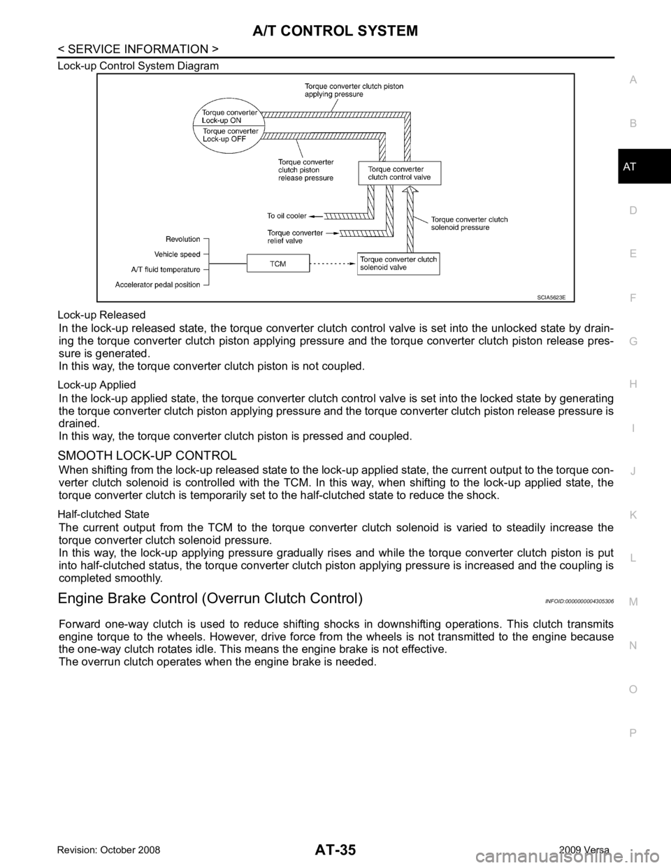
Lock-up Control System Diagram
Lock-up Released In the lock-up released state, the torque converter clutch control valve is set into the unlocked state by drain-
ing the torque converter clutch piston applying pressure and the torque converter clutch piston release pres-
sure is generated.
In this way, the torque converter clutch piston is not coupled.
Lock-up Applied In the lock-up applied state, the torque converter clutch control valve is set into the locked state by generating
the torque converter clutch piston applying pressure and t he torque converter clutch piston release pressure is
drained.
In this way, the torque converter clutch piston is pressed and coupled.
SMOOTH LOCK-UP CONTROL When shifting from the lock-up released state to the lock- up applied state, the current output to the torque con-
verter clutch solenoid is controlled with the TCM. In this way, when shifting to the lock-up applied state, the
torque converter clutch is temporarily set to the half-clutched state to reduce the shock.
Half-clutched State The current output from the TCM to the torque converte r clutch solenoid is varied to steadily increase the
torque converter clutch solenoid pressure.
In this way, the lock-up applying pressure gradually rises and while the torque converter clutch piston is put
into half-clutched status, the torque converter clutch piston applying pressure is increased and the coupling is
completed smoothly.
Engine Brake Control (Overrun Clutch Control) INFOID:0000000004305306
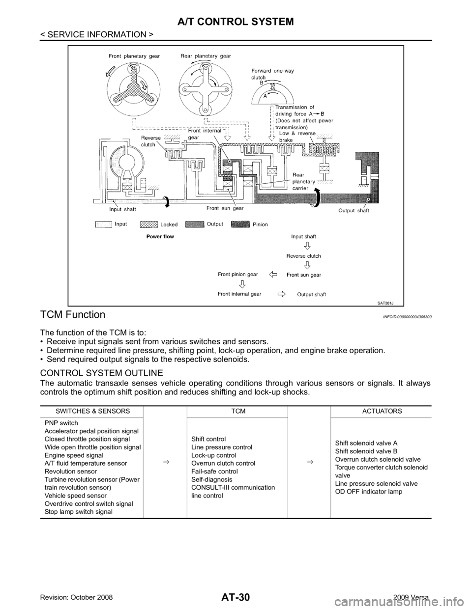
Forward one-way clutch is used to reduce shifting shoc ks in downshifting operations. This clutch transmits
engine torque to the wheels. However, drive force fr om the wheels is not transmitted to the engine because
the one-way clutch rotates idle. This means the engine brake is not effective.
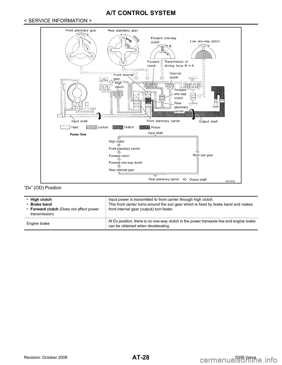
The overrun clutch operates when the engine brake is needed.
