stop start NISSAN LATIO 2009 Service Owner's Guide
[x] Cancel search | Manufacturer: NISSAN, Model Year: 2009, Model line: LATIO, Model: NISSAN LATIO 2009Pages: 4331, PDF Size: 58.04 MB
Page 1168 of 4331
![NISSAN LATIO 2009 Service Owners Guide CVT-224< SERVICE INFORMATION >
[RE0F08B]
TROUBLE DIAGNOSIS
• Before road test, familiarize yourself with all test procedures and items to check.
• Perform tests on all items until s](/img/5/57359/w960_57359-1167.png "NISSAN LATIO 2009 Service Owners Guide CVT-224< SERVICE INFORMATION >
[RE0F08B]
TROUBLE DIAGNOSIS
• Before road test, familiarize yourself with all test procedures and items to check.
• Perform tests on all items until s")
CVT-224< SERVICE INFORMATION >
[RE0F08B]
TROUBLE DIAGNOSIS
• Before road test, familiarize yourself with all test procedures and items to check.
• Perform tests on all items until s pecified symptom is found. Trou-
bleshoot items which check out No Good after road test.
CONSULT-III START PROCEDURE
• Using CONSULT-III, perform a cruise test and record the result.
• Print the result and ensure that shifts and lock-ups take place as per Shift Schedule.
1. Touch “DATA MONITOR” on “SELECT DIAG MODE” screen.
2. Touch “MAIN SIGNALS” to set recording condition.
3. See “Numerical Display”, “Barchart Display” or “Line Graph Display”.
4. Touch “START”.
5. When performing cruise test. Refer to CVT-226, " Cruise Test " .
6. After finishing cruise test part, touch “RECORD”.
7. Touch “STORE”.
8. Touch “BACK”.
9. Touch “DISPLAY”.
10. Touch “PRINT”.
11. Check the monitor data printed out. Check before Engine Is Started INFOID:00000000043055951.
CHECK O/D OFF INDICATOR LAMP
1. Park vehicle on flat surface.
2. Move selector lever to “P” position.
3. Turn ignition switch OFF. Wait at least 5 seconds.
4. Turn ignition switch ON. (Do not start engine.)
Does O/D OFF indicator lamp come on for about 2 seconds? YES >> 1. Turn ignition switch OFF.
2. Perform self-diagnosis and note NG items.Refer to CVT-230, " CONSULT-III Function (TRANSMISSION) " .
3. Go to CVT-224, " Check at Idle " .
NO >> Stop “Road Test”. Go to CVT-325, " O/D OFF Indicator Lamp Does Not Come On " .
Check at Idle INFOID:00000000043055961.
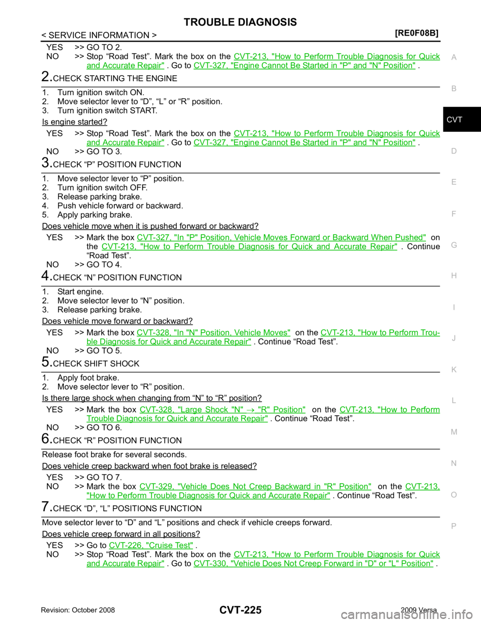
CHECK STARTING THE ENGINE
1. Park vehicle on flat surface.
2. Move selector lever to “P” or “N” position.
3. Turn ignition switch OFF.
4. Turn ignition switch START.
Is engine started? SAT496G
Page 1169 of 4331
CVT
N
O P
YES >> GO TO 2.
NO >> Stop “Road Test”. Mark the box on the CVT-213, " How to Perform Trouble Diagnosis for Quick
and Accurate Repair " . Go to
CVT-327, " Engine Cannot Be Started in "P" and "N" Position " .
YES >> Stop “Road Test”. Mark the box on the
CVT-213, " How to Perform Trouble Diagnosis for Quick
and Accurate Repair " . Go to
CVT-327, " Engine Cannot Be Started in "P" and "N" Position " .
NO >> GO TO 3. YES >> Mark the box
CVT-327, " In "P" Position, Vehicle Moves Forward or Backward When Pushed " on
the CVT-213, " How to Perform Trouble Diagnosis for Quick and Accurate Repair " . Continue
“Road Test”.
NO >> GO TO 4. YES >> Mark the box
CVT-328, " In "N" Position, Vehicle Moves " on the
CVT-213, " How to Perform Trou-
ble Diagnosis for Quick and Accurate Repair " . Continue “Road Test”.
NO >> GO TO 5. “ N ” to “ R ” position?
YES >> Mark the box
CVT-328, " Large Shock "N" " on the
CVT-213, " How to Perform
Trouble Diagnosis for Quick and Accurate Repair " . Continue “Road Test”.
NO >> GO TO 6. YES >> GO TO 7.
NO >> Mark the box CVT-329, " Vehicle Does Not Creep Backward in "R" Position " on the
CVT-213, " How to Perform Trouble Diagnosis for Quick and Accurate Repair " . Continue “Road Test”.
YES >> Go to
CVT-226, " Cruise Test " .
NO >> Stop “Road Test”. Mark the box on the CVT-213, " How to Perform Trouble Diagnosis for Quick
and Accurate Repair " . Go to
CVT-330, " Vehicle Does Not Creep Forward in "D" or "L" Position " .
Page 1209 of 4331
CVT
N
O P
DTC P0730 BELT DAMAGE
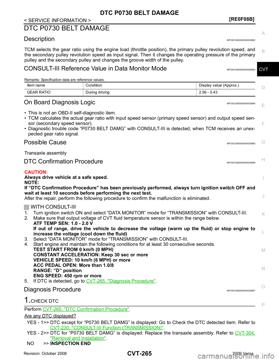
Description INFOID:0000000004305662
TCM selects the gear ratio using the engine load (throttle position), the primary pulley revolution speed, and
the secondary pulley revolution speed as input signal. T hen it changes the operating pressure of the primary
pulley and the secondary pulley and changes the groove width of the pulley.
CONSULT-III Reference Val ue in Data Monitor Mode INFOID:0000000004305663
Remarks: Specification data are reference values.
On Board Diagnosis Logic INFOID:0000000004305664
• This is not an OBD-II self-diagnostic item.
• TCM calculates the actual gear ratio with input speed sensor (primary speed sensor) and output speed sen-
sor (secondary speed sensor).
• Diagnostic trouble code “P0730 BELT DAMG” with CONSUL T-III is detected, when TCM receives an unex-
pected gear ratio signal.
Possible Cause INFOID:0000000004305665
Transaxle assembly
DTC Confirmation Procedure INFOID:0000000004305666
CAUTION:
Always drive vehicle at a safe speed.
NOTE:
If “DTC Confirmation Procedure” has been previously performed, alw ays turn ignition switch OFF and
wait at least 10 seconds before performing the next test.
After the repair, perform the following procedure to confirm the malfunction is eliminated.
WITH CONSULT-III
1. Turn ignition switch ON and select “DATA MO NITOR” mode for “TRANSMISSION” with CONSULT-III.
2. Make sure that output voltage of CVT fluid temperature sensor is within the range below.
ATF TEMP SEN: 1.0 - 2.0 V
If out of range, drive the vehicle to decrease the voltage (warm up the fluid) or stop engine to
increase the voltage (c ool down the fluid)
3. Select “DATA MONITOR” mode for “TRANSMISSION” with CONSULT-III.
4. Start engine and maintain the following conditions for at least 30 consecutive seconds.
TEST START FROM 0 km/h (0 MPH)
CONSTANT ACCELERATION: Keep 30 sec or more
VEHICLE SPEED: 10 km/h (6 MPH) or more
ACC PEDAL OPEN: More than 1.0/8
RANGE: “D” position
ENG SPEED: 450 rpm or more
5. If DTC is detected, go to CVT-265, " Diagnosis Procedure " .
Diagnosis Procedure INFOID:0000000004305667DTC Confirmation Procedure " .
Are any DTC displayed? YES - 1>> DTC except for “P0730 BELT DAMG” is displa
yed: Go to Check the DTC detected item. Refer to
CVT-230, " CONSULT-III Function (TRANSMISSION) " .
YES - 2>> DTC for “P0730 BELT DAMG” is displayed: Replace the transaxle assembly. Refer to CVT-354," Removal and Installation " .
NO >> INSPECTION END
Item name Condition Display value (Approx.)
GEAR RATIO During driving 2.56 - 0.43
Page 1231 of 4331
CVT
N
O P
DTC P0840 TRANSMISSION FLUID
PRESSURE SENSOR A CIRCUIT
(SEC PRESSURE SENSOR)
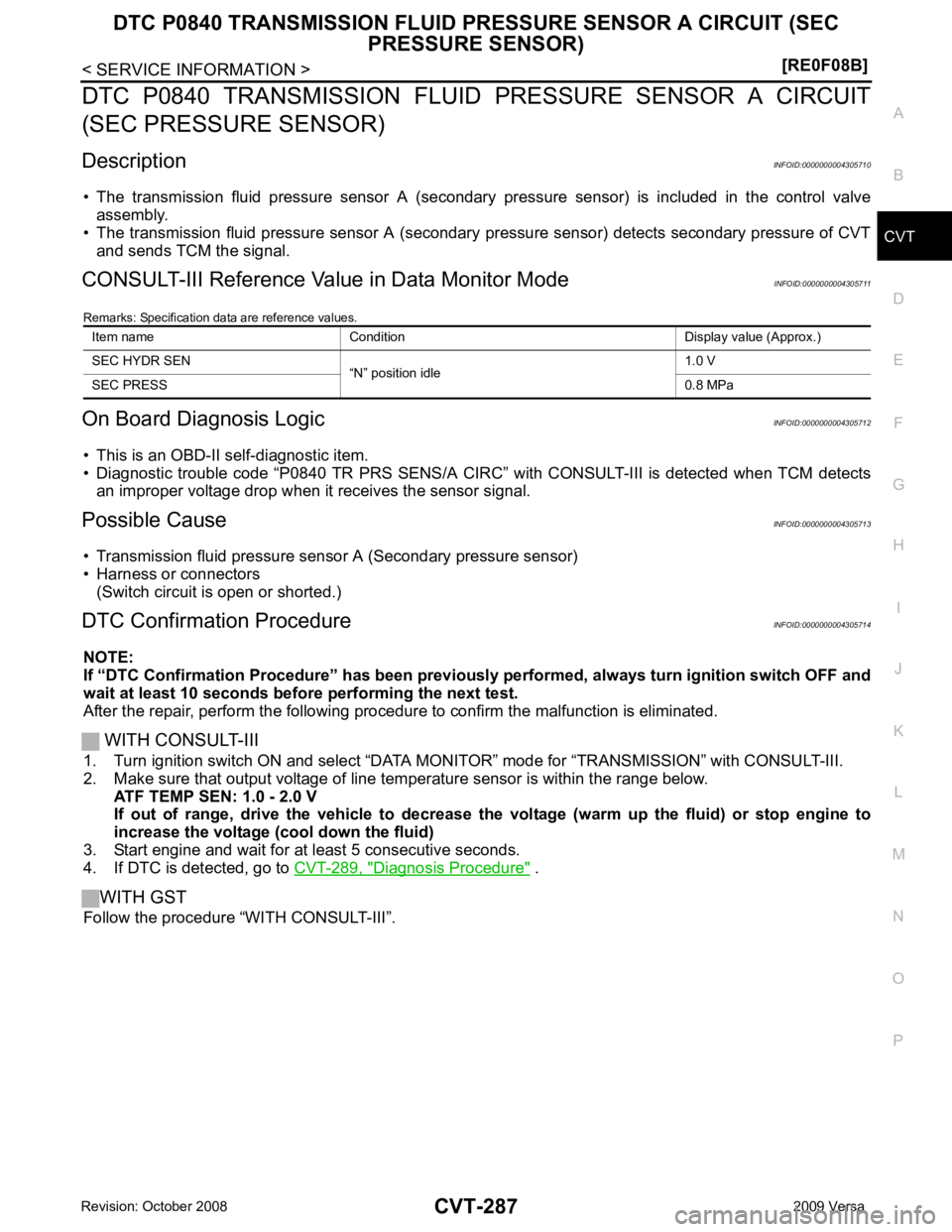
Description INFOID:0000000004305710
• The transmission fluid pressure sensor A (secondary pressure sensor) is included in the control valve
assembly.
• The transmission fluid pressure sensor A (secondary pressure sensor) detects secondary pressure of CVT
and sends TCM the signal.
CONSULT-III Reference Val ue in Data Monitor Mode INFOID:0000000004305711
Remarks: Specification data are reference values.
On Board Diagnosis Logic INFOID:0000000004305712
• This is an OBD-II self-diagnostic item.
• Diagnostic trouble code “P0840 TR PRS SENS/A CIRC” with CONSULT-III is detected when TCM detects
an improper voltage drop when it receives the sensor signal.
Possible Cause INFOID:0000000004305713
• Transmission fluid pressure sensor A (Secondary pressure sensor)
• Harness or connectors (Switch circuit is open or shorted.)
DTC Confirmation Procedure INFOID:0000000004305714
NOTE:
If “DTC Confirmation Procedure” has been previously performed, alw ays turn ignition switch OFF and
wait at least 10 seconds before performing the next test.
After the repair, perform the following procedure to confirm the malfunction is eliminated.
WITH CONSULT-III
1. Turn ignition switch ON and select “DATA MO NITOR” mode for “TRANSMISSION” with CONSULT-III.
2. Make sure that output voltage of line te mperature sensor is within the range below.
ATF TEMP SEN: 1.0 - 2.0 V
If out of range, drive the vehicle to decrease the voltage (warm up the fluid) or stop engine to
increase the voltage (c ool down the fluid)
3. Start engine and wait for at least 5 consecutive seconds.
4. If DTC is detected, go to CVT-289, " Diagnosis Procedure " .
WITH GST
Follow the procedure “WITH CONSULT-III”. Item name Condition Display value (Approx.)
SEC HYDR SEN “N” position idle 1.0 V
SEC PRESS 0.8 MPa
Page 1237 of 4331
CVT
N
O P
DTC P0868 SECONDARY PRESSURE DOWN
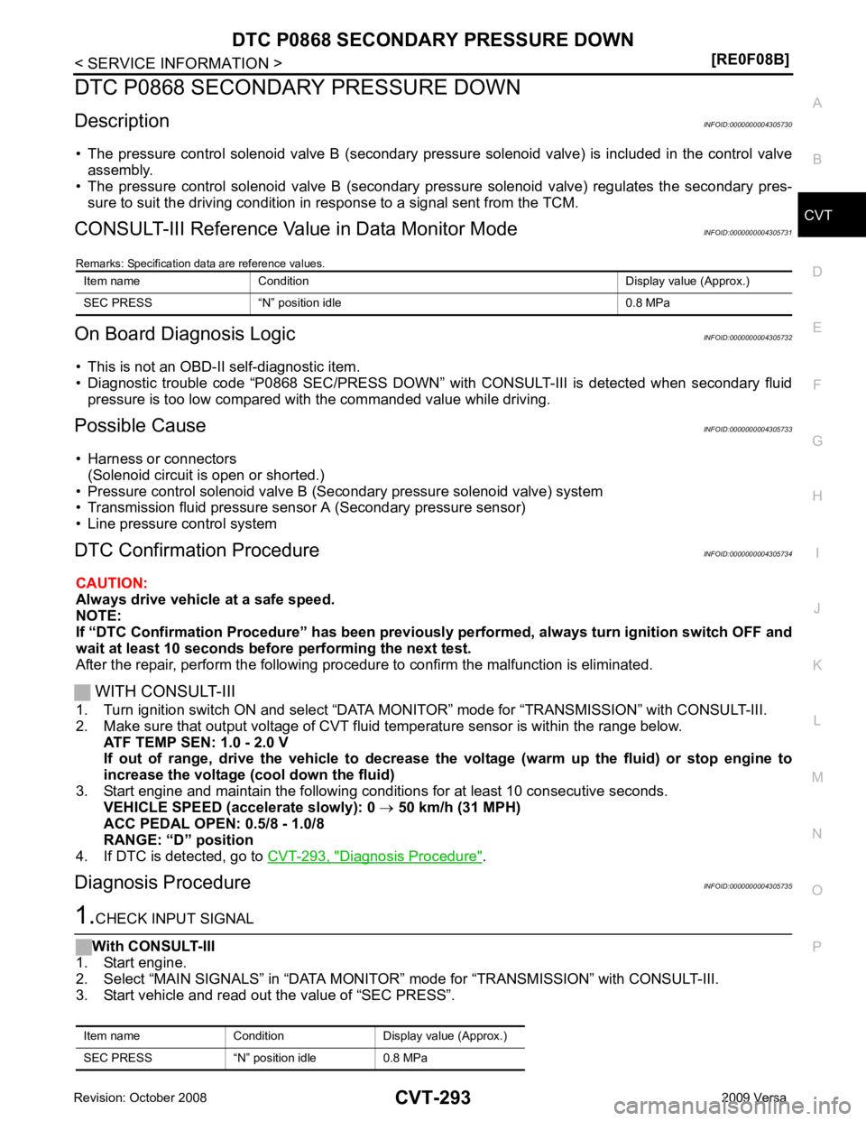
Description INFOID:0000000004305730
• The pressure control solenoid valve B (secondary pressure solenoid valve) is included in the control valve assembly.
• The pressure control solenoid valve B (secondary pressure solenoid valve) regulates the secondary pres-
sure to suit the driving condition in response to a signal sent from the TCM.
CONSULT-III Reference Val ue in Data Monitor Mode INFOID:0000000004305731
Remarks: Specification data are reference values.
On Board Diagnosis Logic INFOID:0000000004305732
• This is not an OBD-II self-diagnostic item.
• Diagnostic trouble code “P0868 SEC/PRESS DOWN” with CONSULT-III is detected when secondary fluid
pressure is too low compared with the commanded value while driving.
Possible Cause INFOID:0000000004305733
• Harness or connectors (Solenoid circuit is open or shorted.)
• Pressure control solenoid valve B (Secondary pressure solenoid valve) system
• Transmission fluid pressure sensor A (Secondary pressure sensor)
• Line pressure control system
DTC Confirmation Procedure INFOID:0000000004305734
CAUTION:
Always drive vehicle at a safe speed.
NOTE:
If “DTC Confirmation Procedure” has been previously performed, alw ays turn ignition switch OFF and
wait at least 10 seconds before performing the next test.
After the repair, perform the following procedure to confirm the malfunction is eliminated.
WITH CONSULT-III
1. Turn ignition switch ON and select “DATA MO NITOR” mode for “TRANSMISSION” with CONSULT-III.
2. Make sure that output voltage of CVT fluid temperature sensor is within the range below.
ATF TEMP SEN: 1.0 - 2.0 V
If out of range, drive the vehicle to decrease the voltage (warm up the fluid) or stop engine to
increase the voltage (c ool down the fluid)
3. Start engine and maintain the following conditions for at least 10 consecutive seconds. VEHICLE SPEED (accelerate slowly): 0 → 50 km/h (31 MPH)
ACC PEDAL OPEN: 0.5/8 - 1.0/8
RANGE: “D” position
4. If DTC is detected, go to CVT-293, " Diagnosis Procedure " .
Diagnosis Procedure INFOID:0000000004305735
Page 1239 of 4331
CVT
N
O P
DTC P1701 TRANSMISSION CONT
ROL MODULE (POWER SUPPLY)
Description INFOID:0000000004305736
When the power supply to the TCM is cut OFF, for exam ple because the battery is removed, and the self-diag-
nosis memory function stop s, malfunction is detected.
NOTE:
Since “P1701 TCM-POWER SUPPLY” will be indicated when replacing TCM, perform diagnosis after
erasing “SELF-DIAG RESULTS”
On Board Diagnosis Logic INFOID:0000000004305737
• This is not an OBD-II self-diagnostic item.
• Diagnostic trouble code “P1701 TCM-POWER SUPPLY” with CONSULT-III is detected when TCM does not
receive the voltage signal from the battery power supply.
• This is not a malfunction message. (Whenever shutti ng OFF a power supply to the TCM, this message
appears on the screen.)
Possible Cause INFOID:0000000004305738
Harness or connectors
(Battery or ignition switch and TCM circuit is open or shorted.)
DTC Confirmation Procedure INFOID:0000000004305739
NOTE:
If “DTC Confirmation Procedure” has been previously conducted, alw ays turn ignition switch OFF and
wait at least 10 seconds before conducting the next test.
After the repair, perform the following procedure to confirm the malfunction is eliminated.
WITH CONSULT-III
1. Turn ignition switch ON. (Do not start engine.)
2. Select “DATA MONITOR” mode for “TRANSMISSION” with CONSULT-III.
3. Wait for at least 2 consecutive seconds.
4. If DTC is detected, go to CVT-297, " Diagnosis Procedure " .
Page 1259 of 4331
CVT
N
O P
DTC P1778 STEP MOTOR - FUNCTION
Description INFOID:0000000004305785
• The step motor is included in the control valve assembly.
• The step motor's 4 aspects of ON/OFF change according to the signal from TCM. As a result, the flow of line
pressure to primary pulley is changed and pulley ratio is controlled.
• This diagnosis item is detected when electrical system is OK, but mechanical system is NG.
• This diagnosis item is detected when the state of the changing the speed mechanism in unit does not oper-
ate normally.
CONSULT-III Reference Val ue in Data Monitor Mode INFOID:0000000004305786
Remarks: Specification data are reference values.
On Board Diagnosis Logic INFOID:0000000004305787
• This is an OBD-II self-diagnostic item.
• Diagnostic trouble code “P1778 STEP MOTR/FNC” with CO NSULT-III is detected under the following condi-
tions.
- When not changing the pulley ratio according to the instruction of TCM.
Possible Cause INFOID:0000000004305788
Step motor
DTC Confirmation Procedure INFOID:0000000004305789
CAUTION:
• Always drive vehicle at a safe speed.
• Before starting “DTC Confirmation Procedure”, confirm “Hi” or “Mid” or “Low” fixation by “PRI SPEED” and “VEHICLE SPEED” on “DATA MONITOR MODE”.
• If hi-geared fixation occurred, go to CVT-316, " Diagnosis Procedure " .
NOTE:
If “DTC Confirmation Procedure” has been previously performed, alw ays turn ignition switch OFF and
wait at least 10 seconds before performing the next test.
After the repair, touch “ERASE” on “SELF-DIAG RESU LTS” and then perform the following procedure to con-
firm the malfunction is eliminated.
WITH CONSULT-III
1. Turn ignition switch ON and select “DATA MO NITOR” mode for “TRANSMISSION” with CONSULT-III.
2. Make sure that output voltage of CVT fluid temperature sensor is within the range below.
ATF TEMP SEN: 1.0 - 2.0 V
If out of range, drive the vehicle to decrease the voltage (warm up the fluid) or stop engine to
increase the voltage (c ool down the fluid)
3. Select “DATA MONITOR” mode for “TRANSMISSION” with CONSULT-III.
4. Start engine and maintain the following conditions for at least 30 consecutive seconds.
TEST START FROM 0 km/h (0 MPH)
CONSTANT ACCELERATION: Keep 30 sec or more
VEHICLE SPEED: 10 km/h (6 MPH) or more
ACC PEDAL OPEN: More than 1.0/8
RANGE: “D” position
ENG SPEED: 450 rpm or more
5. If DTC is detected, go to CVT-316, " Diagnosis Procedure " .
WITH GST
Follow the procedure “WITH CONSULT-III”. Item name Condition Display value (Approx.)
STM STEP During driving−
20 step - 180 step
GEAR RATIO 2.56 - 0.43
Page 1289 of 4331
![NISSAN LATIO 2009 Service Owners Guide SHIFT CONTROL SYSTEM
CVT-345
< SERVICE INFORMATION >
[RE0F08B] D
E
F
G H
I
J
K L
M A
B CVT
N
O P
1. Set selector lever knob (1) in “N” position.
2. Slide knob cover (2) downward.
3. Pull out lock](/img/5/57359/w960_57359-1288.png "NISSAN LATIO 2009 Service Owners Guide SHIFT CONTROL SYSTEM
CVT-345
< SERVICE INFORMATION >
[RE0F08B] D
E
F
G H
I
J
K L
M A
B CVT
N
O P
1. Set selector lever knob (1) in “N” position.
2. Slide knob cover (2) downward.
3. Pull out lock")
SHIFT CONTROL SYSTEM
CVT-345
< SERVICE INFORMATION >
[RE0F08B] D
E
F
G H
I
J
K L
M A
B CVT
N
O P
1. Set selector lever knob (1) in “N” position.
2. Slide knob cover (2) downward.
3. Pull out lock pin (3) from selector lever knob (1).
4. Remove selector lever knob (1) and knob cover (2) as a set from selector lever.
CAUTION:
Do not push selector button.
INSTALLATION 1. Insert lock pin (1) to selector lever knob (2).
2. Install knob cover (3) to selector lever knob (2).
3. Set selector lever in “N” position.
4. Install selector lever knob onto selector lever until a click is felt. CAUTION:
• Do not tilt selector lever knob when installing. Install it
straight, and do not tap or ap ply any shock to install it.
• Do not push selector button.
Adjustment of CVT Position INFOID:0000000004305819
CAUTION:
Make sure that parking brake is applied before adjustment.
1. Loosen the control cable nut (A) and place the manual lever (1) in “P” position.
2. Place selector lever in “P” position.
3. Push the control cable (2) in with a load of 9.8 N (approximately 1 kg, 2.2 lb). Release the control cable and temporarily tighten
the control cable nut.
NOTE:
Do not move the manual lever. Make sure the manual lever
stays in the “P” position.
4. Tighten the control cable nut. CAUTION:
Secure the manual lever when tightening nut.
5. Check the operation of the CVT. Refer to CVT-345, " Checking of CVT Position " .
Checking of CVT Position INFOID:0000000004305820
1. Place selector lever in “P” position, and tu rn ignition switch ON. (Do not start engine.)
2. Make sure selector lever can be shifted to other than “P” position when brake pedal is depressed. Also
make sure selector lever can be shifted from “P” position only when brake pedal is depressed.
3. Move the selector lever and check for excessive effort, sticking, noise or rattle.
4. Confirm the selector lever stops at each position with the feel of engagement when it is moved through all
the positions. Check that t he actual position of the selector lever matches the position shown by the shift
position indicator and the manual lever on the transaxle. SCIA6971E
SCIA6972E
Control cable nut: Refer to
CVT-341, " Removal
and Installation " . WCIA0608E
Page 1312 of 4331
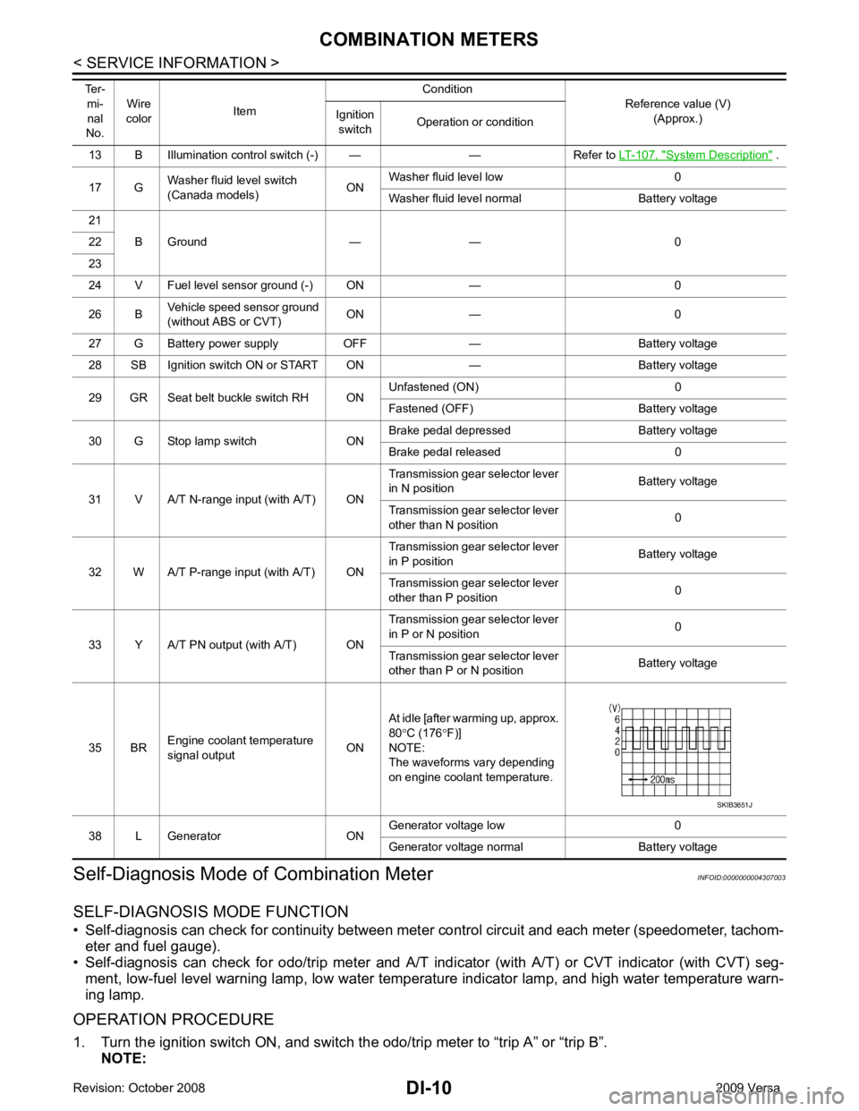
System Description " .
17 G Washer fluid level switch
(Canada models) ONWasher fluid level low 0
Washer fluid level normal Battery voltage
21 B Ground — — 0
22
23
24 V Fuel level sensor ground (-) ON — 0
26 B Vehicle speed sensor ground
(without ABS or CVT) ON — 0
27 G Battery power supply OFF — Battery voltage
28 SB Ignition switch ON or START ON — Battery voltage
29 GR Seat belt buckle switch RH ON Unfastened (ON) 0
Fastened (OFF) Battery voltage
30 G Stop lamp switch ON Brake pedal depressed Battery voltage
Brake pedal released 0
31 V A/T N-range input (with A/T) ON Transmission gear selector lever
in N position Battery voltage
Transmission gear selector lever
other than N position 0
32 W A/T P-range input (with A/T) ON Transmission gear selector lever
in P position Battery voltage
Transmission gear selector lever
other than P position 0
33 Y A/T PN output (with A/T) ON Transmission gear selector lever
in P or N position 0
Transmission gear selector lever
other than P or N position Battery voltage
35 BR Engine coolant temperature
signal output ONAt idle [after warming up, approx.
80 °C (176 °F)]
NOTE:
The waveforms vary depending
on engine coolant temperature.
38 L Generator ON Generator voltage low 0
Generator voltage normal Battery voltage
Ter-
mi-
nal
No. Wire
color Item Condition
Reference value (V)
(Approx.)
Ignition
switch Operation or condition
Page 1361 of 4331

EC
A
N
O P
Diagnosis Procedure ...........................................
..
349
P0507 ISC SYSTEM ....................................... ..351
Description .......................................................... ..351
DTC Logic ........................................................... ..351
Diagnosis Procedure ........................................... ..351
P0603 ECM POWER SUPPLY ....................... ..353
Description .......................................................... ..353
DTC Logic ........................................................... ..353
Diagnosis Procedure ........................................... ..353
P0605 ECM ..................................................... ..355
Description .......................................................... ..355
DTC Logic ........................................................... ..355
Diagnosis Procedure ........................................... ..356
P0607 ECM ..................................................... ..357
Description .......................................................... ..357
DTC Logic ........................................................... ..357
Diagnosis Procedure ........................................... ..357
P0643 SENSOR POWER SUPPLY ............... ..358
DTC Logic ........................................................... ..358
Wiring Diagram ................................................... ..359
Diagnosis Procedure ........................................... ..359
P0850 PNP SWITCH ...................................... ..362
Description .......................................................... ..362
DTC Logic ........................................................... ..362
Component Function Check ................................ ..363
Wiring Diagram ................................................... ..364
Diagnosis Procedure ........................................... ..364
P1148 CLOSED LOOP CONTROL ................ ..367
DTC Logic ........................................................... ..367
P1217 ENGINE OVER TEMPERATURE ....... ..368
DTC Logic ........................................................... ..368
Component Function Check ................................ ..368
Diagnosis Procedure ........................................... ..369
P1225 TP SENSOR ........................................ ..372
Description .......................................................... ..372
DTC Logic ........................................................... ..372
Diagnosis Procedure ........................................... ..372
Special Repair Requirem ent .................................373
P1226 TP SENSOR ........................................ ..374
Description .......................................................... ..374
DTC Logic ........................................................... ..374
Diagnosis Procedure ........................................... ..374
Special Repair Requirem ent .................................375
P1421 COLD START CONTROL ................... ..376
Description .......................................................... ..376
DTC Logic ........................................................... ..376
Diagnosis Procedure ........................................... ..376
P1715 INPUT SPEED SENSOR (PRIMARY
SPEED SENSOR) .......................................... ..
378
Description .......................................................... ..378 DTC Logic ............................................................
..378
Diagnosis Procedure ........................................... ..378
P1805 BRAKE SWITCH ................................. 380
Description ........................................................... ..380
DTC Logic ............................................................ ..380
Wiring Diagram .................................................... ..381
Diagnosis Procedure ........................................... ..381
Component Inspection (Stop Lamp Switch) ........ ..383
P2100, P2103 THROTTLE CONTROL MO-
TOR RELAY .................................................... 384
Description ........................................................... ..384
DTC Logic ............................................................ ..384
Wiring Diagram .................................................... ..385
Diagnosis Procedure ........................................... ..385
P2101 ELECTRIC THROTTLE CONTROL
FUNCTION ....... ............................................... 388
Description ........................................................... ..388
DTC Logic ............................................................ ..388
Wiring Diagram .................................................... ..389
Diagnosis Procedure ........................................... ..389
Component Inspection ......................................... ..392
Special Repair Requiremen t ..................................392
P2118 THROTTLE CONTROL MOTOR ......... 393
Description ........................................................... ..393
DTC Logic ............................................................ ..393
Wiring Diagram .................................................... ..394
Diagnosis Procedure ........................................... ..394
Component Inspection ......................................... ..395
Special Repair Requiremen t ..................................396
P2119 ELECTRIC THROTTLE CONTROL
ACTUATOR ..................................................... 397
Description ........................................................... ..397
DTC Logic ............................................................ ..397
Diagnosis Procedure ........................................... ..397
Special Repair Requiremen t ..................................398
P2122, P2123 APP SENSOR ......................... 399
Description ........................................................... ..399
DTC Logic ............................................................ ..399
Wiring Diagram .................................................... ..400
Diagnosis Procedure ........................................... ..400
Component Inspection ......................................... ..402
Special Repair Requiremen t ..................................402
P2127, P2128 APP SENSOR ......................... 403
Description ........................................................... ..403
DTC Logic ............................................................ ..403
Wiring Diagram .................................................... ..404
Diagnosis Procedure ........................................... ..404
Component Inspection ......................................... ..406
Special Repair Requiremen t ..................................407
P2135 TP SENSOR ......................................... 408
Description ........................................................... ..408
DTC Logic ............................................................ ..408