wheel bolts NISSAN LATIO 2009 Service Repair Manual
[x] Cancel search | Manufacturer: NISSAN, Model Year: 2009, Model line: LATIO, Model: NISSAN LATIO 2009Pages: 4331, PDF Size: 58.04 MB
Page 59 of 4331
AT-54< SERVICE INFORMATION >
TROUBLE DIAGNOSIS
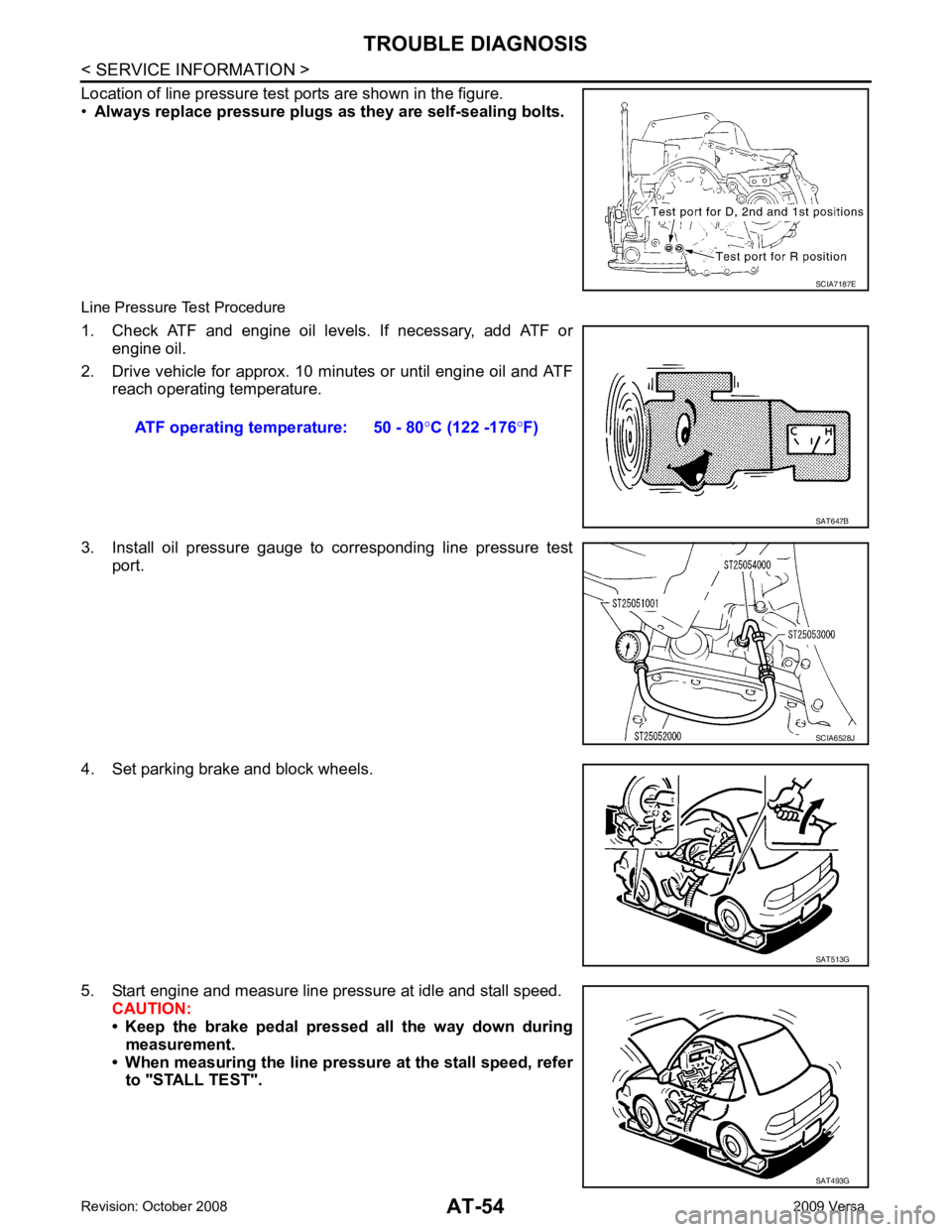
Location of line pressure test ports are shown in the figure.
• Always replace pressure plugs as they are self-sealing bolts.
Line Pressure Test Procedure
1. Check ATF and engine oil levels. If necessary, add ATF or engine oil.
2. Drive vehicle for approx. 10 minutes or until engine oil and ATF reach operating temperature.
3. Install oil pressure gauge to corresponding line pressure test port.
4. Set parking brake and block wheels.
5. Start engine and measure line pressure at idle and stall speed. CAUTION:
• Keep the brake pedal pressed all the way down during
measurement.
• When measuring the line pressure at the stall speed, refer to "STALL TEST". SCIA7187E
ATF operating temperature: 50 - 80
°C (122 -176 °F) SAT647B
SCIA6528J
SAT513G
SAT493G
Page 829 of 4331
BR
N
O P
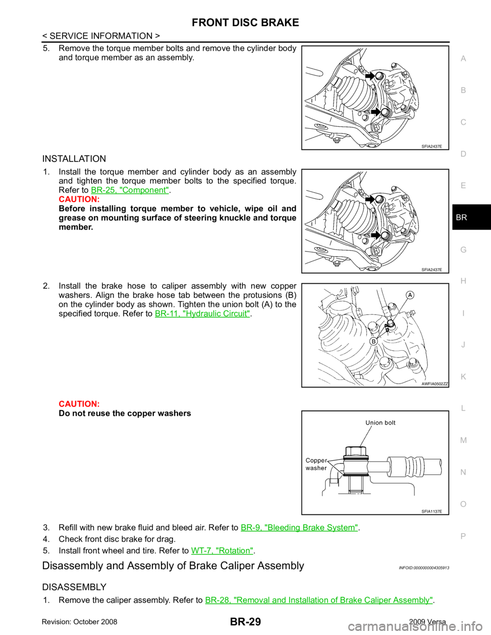
5. Remove the torque member bolts and remove the cylinder body
and torque member as an assembly.
INSTALLATION 1. Install the torque member and cylinder body as an assembly and tighten the torque member bolts to the specified torque.
Refer to BR-25, " Component " .
CAUTION:
Before installing torque member to vehicle, wipe oil and
grease on mounting surface of steering knuckle and torque
member.
2. Install the brake hose to caliper assembly with new copper washers. Align the brake hose tab between the protusions (B)
on the cylinder body as shown. Tighten the union bolt (A) to the
specified torque. Refer to BR-11, " Hydraulic Circuit " .
CAUTION:
Do not reuse the copper washers
3. Refill with new brake fluid and bleed air. Refer to BR-9, " Bleeding Brake System " .
4. Check front disc brake for drag.
5. Install front wheel and tire. Refer to WT-7, " Rotation " .
Disassembly and Assembly of Brake Caliper Assembly INFOID:0000000004305913
DISASSEMBLY 1. Remove the caliper assembly. Refer to BR-28, " Removal and Installation of Brake Caliper Assembly " .AWFIA0502ZZ
SFIA1137E
Page 830 of 4331
BR-30< SERVICE INFORMATION >
FRONT DISC BRAKE
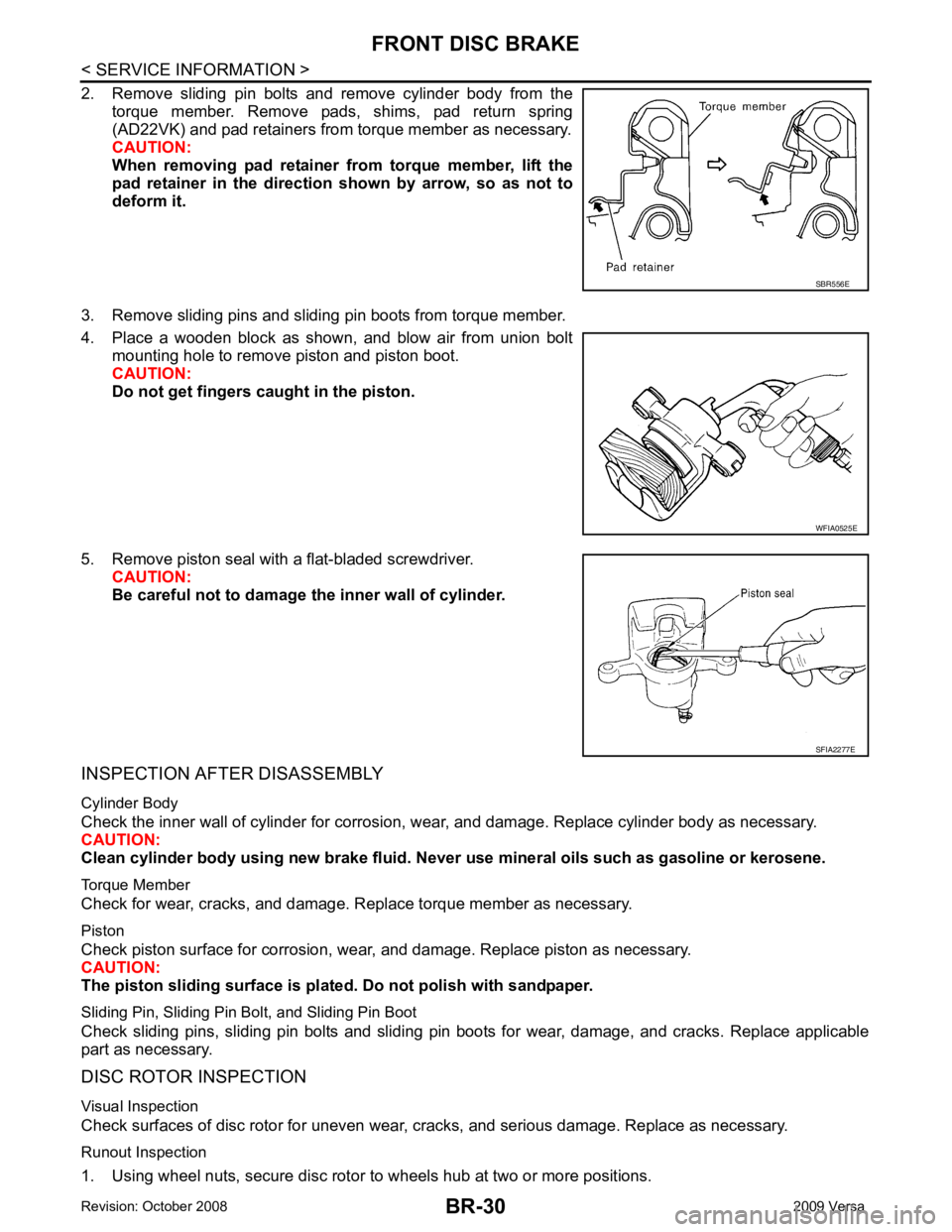
2. Remove sliding pin bolts and remove cylinder body from the torque member. Remove pads, shims, pad return spring
(AD22VK) and pad retainers from torque member as necessary.
CAUTION:
When removing pad retainer fr om torque member, lift the
pad retainer in the direction shown by arrow, so as not to
deform it.
3. Remove sliding pins and sliding pin boots from torque member.
4. Place a wooden block as shown, and blow air from union bolt mounting hole to remove piston and piston boot.
CAUTION:
Do not get fingers caught in the piston.
5. Remove piston seal with a flat-bladed screwdriver. CAUTION:
Be careful not to damage the inner wall of cylinder.
INSPECTION AFTER DISASSEMBLY
Cylinder Body
Check the inner wall of cylinder for corrosion, w ear, and damage. Replace cylinder body as necessary.
CAUTION:
Clean cylinder body using new brake fluid. Never use mineral oils such as gasoline or kerosene.
Torque Member
Check for wear, cracks, and damage. R eplace torque member as necessary.
Piston
Check piston surface for corrosion, wear, and damage. Replace piston as necessary.
CAUTION:
The piston sliding surface is plated . Do not polish with sandpaper.
Sliding Pin, Sliding Pin Bolt, and Sliding Pin Boot
Check sliding pins, sliding pin bolts and sliding pin boots for wear, damage, and cracks. Replace applicable
part as necessary.
DISC ROTOR INSPECTION
Visual Inspection
Check surfaces of disc rotor for uneven wear, cr acks, and serious damage. Replace as necessary.
Runout Inspection
1. Using wheel nuts, secure disc rotor to wheels hub at two or more positions. SBR556E
WFIA0525E
SFIA2277E
Page 837 of 4331
BR
N
O P
5. Connect the parking brake rear cable to the operating lever.
6. Install the shoe assembly. After assembly, be sure that each part is installed properly. CAUTION:
Do not damage the wheel cylinder piston boot.
7. Install the brake drum.
8. Depress brake pedal for several times (approximately 2 or 3 times).
9. Adjust clearance of brake shoe. Refer to PB-5, " On-Vehicle Service " .
10. Install rear wheel and tire. Refer to WT-7, " Rotation " .
Removal and Installati on of Wheel Cylinder INFOID:0000000004305917
REMOVAL 1. Drain the brake fluid. Refer to BR-9, " Drain and Refill " .
2. Remove the rear brake shoe assembly. Refer to BR-34, " Removal and Installation of Drum Brake Assem-
bly " .
3. Remove the bleed valve.
4. Disconnect the brake tube from the wheel cylinder.
5. Remove the wheel cylinder bolts and then remo ve the wheel cylinder from the back plate.
INSTALLATION Installation is in the reverse order of removal.
• Tighten bolts and bleed valve to the specified torque. Refer to BR-33, " Component " .
• Refill with new brake fluid and bleed the air. Refer to BR-9, " Bleeding Brake System " .
Disassembly and Assemb ly of Wheel Cylinder INFOID:0000000004305918
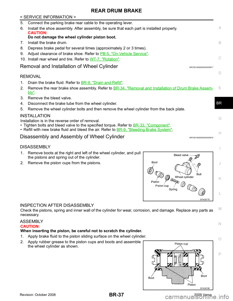
DISASSEMBLY 1. Remove boots at the right and left of the wheel cylinder, and pull the pistons and spring out of the cylinder.
2. Remove the piston cups from the pistons.
INSPECTION AFTER DISASSEMBLY Check the pistons, spring and inner wall of the cylinder for wear, corrosion, and damage. Replace any parts as
necessary.
ASSEMBLY CAUTION:
When inserting the piston, be caref ul not to scratch the cylinder.
1. Apply brake fluid to the piston sliding surface on the wheel cylinder.
2. Apply rubber grease to the piston cups and boots and assemble the wheel cylinder as shown.
Page 875 of 4331
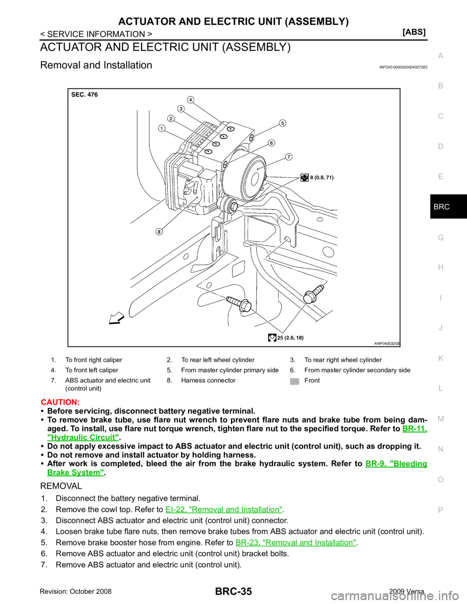
BRC
N
O P
ACTUATOR AND ELECTRIC UNIT (ASSEMBLY)
Removal and Installation INFOID:0000000004307283
CAUTION:
• Before servicing, disconnect battery negative terminal.
• To remove brake tube, use flare nut wrench to pr event flare nuts and brake tube from being dam-
aged. To install, use flare nut torque wrench, ti ghten flare nut to the specified torque. Refer to BR-11," Hydraulic Circuit " .
• Do not apply excessive impact to ABS actuator and elect ric unit (control unit), such as dropping it.
• Do not remove and install actuator by holding harness.
• After work is completed, bleed the air from the brake hydraulic system. Refer to BR-9, " Bleeding
Brake System " .
REMOVAL 1. Disconnect the battery negative terminal.
2. Remove the cowl top. Refer to EI-22, " Removal and Installation " .
3. Disconnect ABS actuator and electric unit (control unit) connector.
4. Loosen brake tube flare nuts, then remove brake tubes from ABS actuator and electric unit (control unit).
5. Remove brake booster hose from engine. Refer to BR-23, " Removal and Installation " .
6. Remove ABS actuator and electric unit (control unit) bracket bolts.
7. Remove ABS actuator and electric unit (control unit). 1. To front right caliper 2. To rear left wheel cylinder 3. To rear right wheel cylinder
4. To front left caliper 5. From master cylinder primary side 6. From master cylinder secondary side
7. ABS actuator and electric unit (control unit) 8. Harness connector Front
Page 891 of 4331
CL
N
O P
CLUTCH DISC, CLUTCH COVER AND FLYWHEEL
Removal and Installation INFOID:0000000004305174
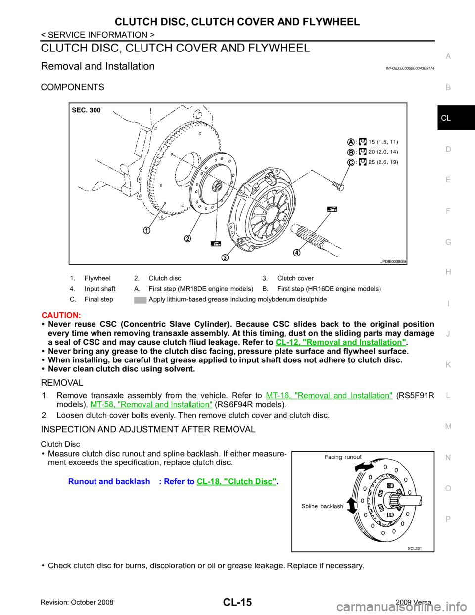
COMPONENTS
CAUTION:
• Never reuse CSC (Concentric Slave Cylinder). B ecause CSC slides back to the original position
every time when removing transaxle assembly. At th is timing, dust on the sliding parts may damage
a seal of CSC and may cause clut ch fliud leakage. Refer to CL-12, " Removal and Installation " .
• Never bring any grease to the clutch disc faci ng, pressure plate surface and flywheel surface.
• When installing, be careful that grease applied to input shaft does not adhere to clutch disc.
• Never clean clutch disc using solvent.
REMOVAL 1. Remove transaxle assembly from the vehicle. Refer to MT-16, " Removal and Installation " (RS5F91R
models), MT-58, " Removal and Installation " (RS6F94R models).
2. Loosen clutch cover bolts evenly. Then remove clutch cover and clutch disc.
INSPECTION AND ADJUSTMENT AFTER REMOVAL
Clutch Disc • Measure clutch disc runout and spline backlash. If either measure- ment exceeds the specificat ion, replace clutch disc.
• Check clutch disc for burns, discoloration or oil or grease leakage. Replace if necessary.
1. Flywheel 2. Clutch disc 3. Clutch cover
4. Input shaft A. First step (MR18DE engine models) B. First step (HR16DE engine models)
C. Final step Apply lithium-based grease including molybdenum disulphide Clutch Disc " .
Page 914 of 4331
Changing Engine Coolant " .
CAUTION:
• Perform this step when the engine is cold.
• Never spill engine coolant on drive belts.
2. Steer front wheel to the right.
3. Remove front fender protector (RH). Refer to EI-24, " Removal and Installation " .
4. Loosen mounting bolts of water pump pulley before loosening belt tension of drive belt.
5. Remove drive belt. Refer to EM-15, " Removal and Installation " .
6. Remove water pump pulley.
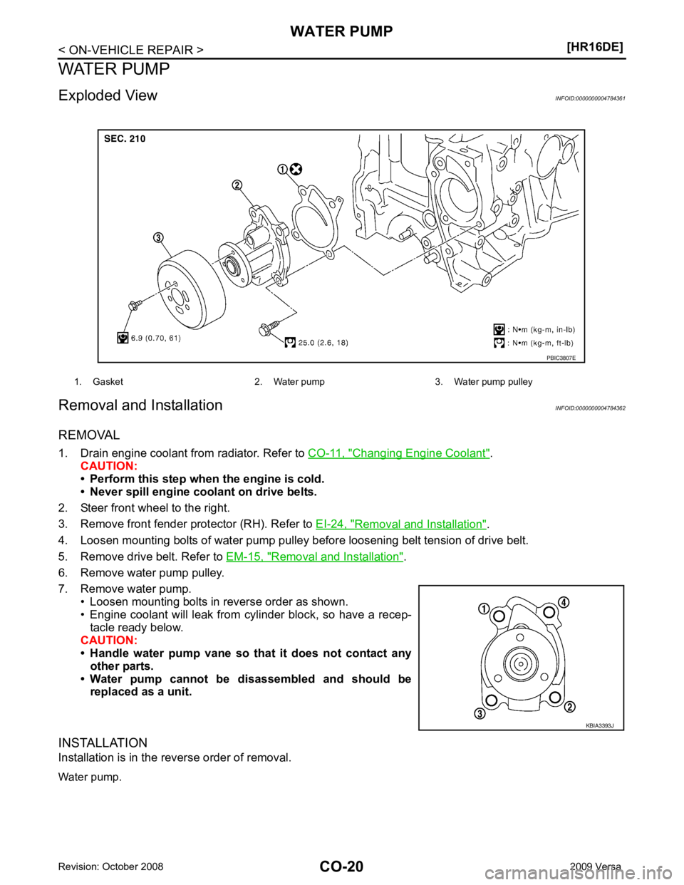
7. Remove water pump. • Loosen mounting bolts in reverse order as shown.
• Engine coolant will leak from cylinder block, so have a recep-
tacle ready below.
CAUTION:
• Handle water pump vane so that it does not contact any
other parts.
• Water pump cannot be disassembled and should be replaced as a unit.
INSTALLATION
Installation is in the reverse order of removal.
Water pump. 1. Gasket 2. Water pump 3. Water pump pulley
KBIA3393J
Page 3040 of 4331
EM
NP
O
DISASSEMBLY AND ASSEMBLY
ENGINE STAND SETTING
Setting INFOID:0000000004784310
NOTE:
Explained here is how to disassemble with engine stand supporting transmission surface. When using differ-
ent type of engine stand, note with difference in steps and etc.
1. Remove the engine and the transaxle assembly from the vehicle, and separate the transaxle from the
engine. Refer to EM-88, " Exploded View " .
2. Remove clutch cover and clutch disc (if equipped). Refer to CL-15, " Removal and Installation " .
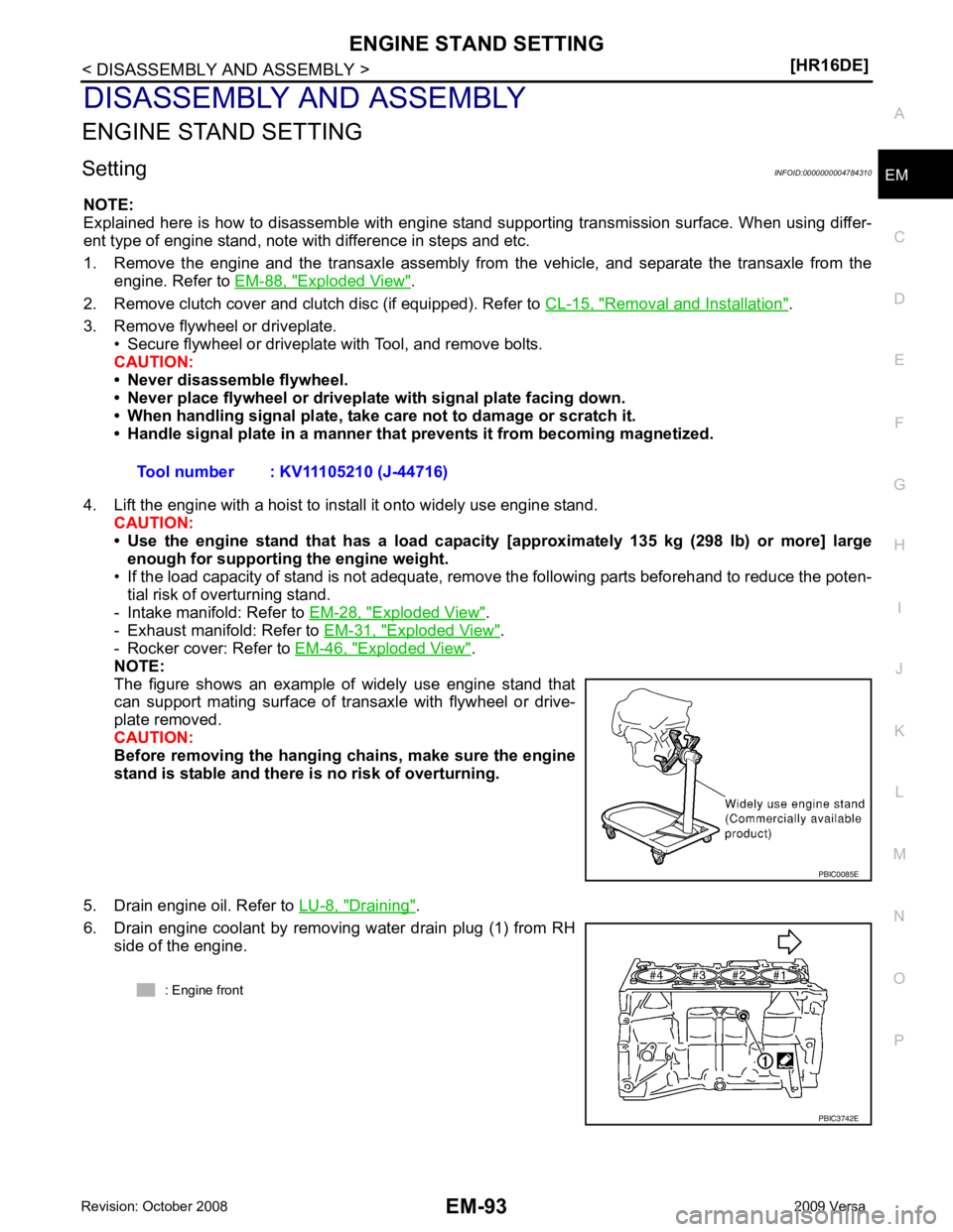
3. Remove flywheel or driveplate. • Secure flywheel or driveplate with Tool, and remove bolts.
CAUTION:
• Never disassemble flywheel.
• Never place flywheel or driveplate with signal plate facing down.
• When handling signal plate, take car e not to damage or scratch it.
• Handle signal plate in a manner that prevents it from becoming magnetized.
4. Lift the engine with a hoist to install it onto widely use engine stand. CAUTION:
• Use the engine stand that has a load capacity [approximately 135 kg (298 lb) or more] large
enough for supporting the engine weight.
• If the load capacity of stand is not adequate, remove the following parts beforehand to reduce the poten-
tial risk of overturning stand.
- Intake manifold: Refer to EM-28, " Exploded View " .
- Exhaust manifold: Refer to EM-31, " Exploded View " .
- Rocker cover: Refer to EM-46, " Exploded View " .
NOTE:
The figure shows an example of widely use engine stand that
can support mating surface of transaxle with flywheel or drive-
plate removed.
CAUTION:
Before removing the hanging chains, make sure the engine
stand is stable and there is no risk of overturning.
5. Drain engine oil. Refer to LU-8, " Draining " .
6. Drain engine coolant by removing water drain plug (1) from RH side of the engine. Tool number : KV11105210 (J-44716)
Page 3049 of 4331
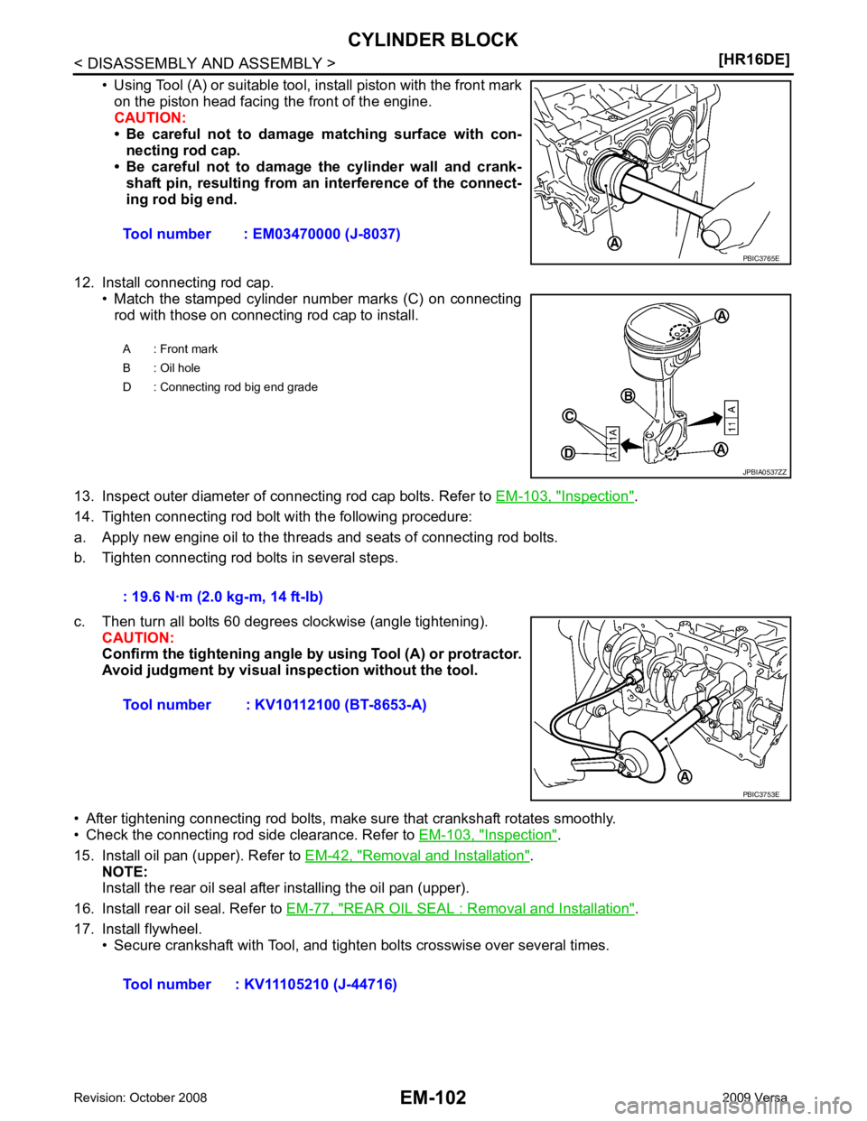
Inspection " .
14. Tighten connecting rod bolt with the following procedure:
a. Apply new engine oil to the threads and seats of connecting rod bolts.
b. Tighten connecting rod bolts in several steps.
c. Then turn all bolts 60 degrees clockwise (angle tightening). CAUTION:
Confirm the tightening angle by using Tool (A) or protractor.
Avoid judgment by visual inspection without the tool.
• After tightening connecting rod bolts, make sure that crankshaft rotates smoothly.
• Check the connecting rod side clearance. Refer to EM-103, " Inspection " .
15. Install oil pan (upper). Refer to EM-42, " Removal and Installation " .
NOTE:
Install the rear oil seal after installing the oil pan (upper).
16. Install rear oil seal. Refer to EM-77, " REAR OIL SEAL : Removal and Installation " .
17. Install flywheel. • Secure crankshaft with Tool, and tighten bolts crosswise over several times.Tool number : EM03470000 (J-8037)
Page 3080 of 4331
![NISSAN LATIO 2009 Service Repair Manual PREPARATION
EM-133
< SERVICE INFORMATION >
[MR18DE] C
D E
F
G H
I
J
K L
M A EM
NP
O
Valve guide reamer (1): Reaming valve guide inner hole
(2): Reaming hole for oversize valve guide
(J-43897-18)
(J-43 NISSAN LATIO 2009 Service Repair Manual PREPARATION
EM-133
< SERVICE INFORMATION >
[MR18DE] C
D E
F
G H
I
J
K L
M A EM
NP
O
Valve guide reamer (1): Reaming valve guide inner hole
(2): Reaming hole for oversize valve guide
(J-43897-18)
(J-43](/img/5/57359/w960_57359-3079.png)
PREPARATION
EM-133
< SERVICE INFORMATION >
[MR18DE] C
D E
F
G H
I
J
K L
M A EM
NP
O
Valve guide reamer (1): Reaming valve guide inner hole
(2): Reaming hole for oversize valve guide
(J-43897-18)
(J-43897-12)
Oxygen sensor thread cleaner Reconditioning the exhaust system threads
before installing a new oxygen sensor (Use
with anti-seize lubricant shown below.)
a: J-43897-18 (18 mm dia.) for zirconia ox-
ygen sensor
b: J-43897-12 (12 mm dia.) for titania oxy-
gen sensor
Anti-seize lubricant (Permatex 133AR
or equivalent meeting MIL specifica-
tion MIL-A-907) Lubricating oxygen sensor thread cleaning
tool when reconditioning exhaust system
threads
E20 Torx® Socket
(J-45816) Removing and installing drive plate and fly-
wheel bolts
(Kent-Moore No.)
Tool name Description PBIC4013E
AEM488
AEM489
LBIA0285E