high NISSAN LATIO 2009 Service Repair Manual
[x] Cancel search | Manufacturer: NISSAN, Model Year: 2009, Model line: LATIO, Model: NISSAN LATIO 2009Pages: 4331, PDF Size: 58.04 MB
Page 14 of 4331
AT
N
O P
• The valve body contains precision parts and requires extreme care when parts are removed and serviced.
Place disassembled valve body parts in order for easier and proper assembly. Care will also prevent springs
and small parts from becoming scattered or lost.
• Properly installed valves, sleeves, plugs, etc. will slide along bores in valve body under their own weight.
• Before assembly, apply a coat of recommended ATF to all parts. Apply petroleum jelly to protect O-rings and
seals, or hold bearings and washers in pl ace during assembly. Do not use grease.
• Extreme care should be taken to avoid damage to O-rings, seals and gaskets when assembling.
• Clean or replace ATF cooler if excessive foreign material is found in oil pan or clogging strainer. Refer to AT-18, " A/T Fluid Cooler Cleaning " .
• After overhaul, refill the A/T with new ATF.
• When the A/T drain plug is removed, only some of the fluid is drained. Old A/T fluid will remain in torque con- verter and ATF cooling system.
Always follow the procedures under “Changing A/T Fluid” in the AT section when changing A/T fluid. Refer to
AT-17, " Changing A/T Fluid " ,
AT-17, " Checking A/T Fluid " .
Service Notice or Precaution INFOID:0000000004305292
ATF COOLER SERVICE If A/T fluid contains frictional material (clutches, bands, etc.), or if an A/T is repaired, overhauled, or replaced,
inspect and clean the A/T oil cooler mounted in the radiator or replace the radiator. Flush cooler lines using
cleaning solvent and compressed air after repair. Check Serv ice Bulletins for latest A/T oil cooler cleaning pro-
cedure. For radiator replacement, refer to CO-16, " Removal and Installation " (HR16DE engine models),
CO-38, " Removal and Installation " (MR18DE engine models).
TORQUE CONVERTER SERVICE The torque converter should be replaced under any of the following conditions:
• External leaks in the hub weld area.
• Converter hub is scored or damaged.
• Converter pilot is broken, damaged or fits poorly into crankshaft.
• Steel particles are found after flushing the cooler and cooler lines.
• Pump is damaged or steel particles are found in the converter.
• Vehicle has TCC shudder and/or no TCC apply. Replace only after all hydraulic and electrical diagnoses
have been made. (Converter clutch material may be glazed.)
• Converter is contaminated with engi ne coolant containing antifreeze.
• Internal malfunction of stator roller clutch.
• Heavy clutch debris due to overheating (blue converter).
• Steel particles or clutch lining material found in flui d filter or on magnet when no internal parts in unit are
worn or damaged — indicates that lining material came from converter.
The torque converter should not be replaced if:
• The fluid has an odor, is discolored, and there is no evidence of metal or clutch facing particles.
• The threads in one or more of the converter bolt holes are damaged.
• A/T malfunction did not display evidence of damaged or worn internal parts, steel particles or clutch plate lin-
ing material in unit and inside the fluid filter.
• Vehicle has been exposed to high mileage (only). The e xception may be where the torque converter clutch
dampener plate lining has seen excess wear by vehicles operated in heavy and/or constant traffic, such as
taxi, delivery or police use.
OBD-II SELF-DIAGNOSIS • A/T self-diagnosis is performed by the TCM in combination with the ECM. The results can be read through the blinking pattern of the OD OFF indicator lamp or the malfunction indicator lamp (MIL). Refer to the table
on AT-83, " Diagnosis Procedure without CONSULT-III " for the indicator used to display each self-diagnostic
result.
• The self-diagnostic results indicated by the MIL ar e automatically stored in both the ECM and TCM memo-
ries.
Always perform the procedure “HOW TO ERASE DTC” on AT-39, " OBD-II Diagnostic Trouble Code
(DTC) " to complete the repair and avo
id unnecessary blinking of the MIL.
• The following self-diagnostic items can be detected us ing ECM self-diagnostic results mode* only when the
OD OFF indicator lamp does not indicate any malfunctions.
- PNP switch
- A/T 1st, 2nd, 3rd, or 4th gear function
*: For details of OBD-II, refer to AT-39 .
Page 23 of 4331
Checking A/T Fluid " .
A/T Fluid Cooler Cleaning INFOID:0000000004305297
Whenever the A/T is repaired, overhauled, or replaced, the A/T fluid cooler mounted in the radiator must be
inspected and cleaned.
Metal debris and friction material, if present, can becom e trapped in the A/T fluid cooler. This debris can con-
taminate the newly serviced A/T or, in severe cases, can bloc k or restrict the flow of A/T fluid. In either case,
malfunction of the newly serviced A/T may result.
Debris, if present, may build up as A/T fluid enters the c ooler inlet. It will be necessary to back flush the cooler
through the cooler outlet in order to flush out any built up debris.
A/T FLUID COOLER CLEANING PROCEDURE
1. Identify the A/T inlet and outlet fluid cooler hoses.
2. Position an oil pan under the A/T inlet and outlet fluid cooler hoses.
3. Disconnect the A/T fluid cooler inlet and outlet rubber hoses from the steel cooler tubes or bypass valve.
NOTE:
Replace the cooler hoses if rubber material from the hose
remains on the tube fitting.
4. Allow any A/T fluid that remains in the cooler hoses to drain into
the oil pan.
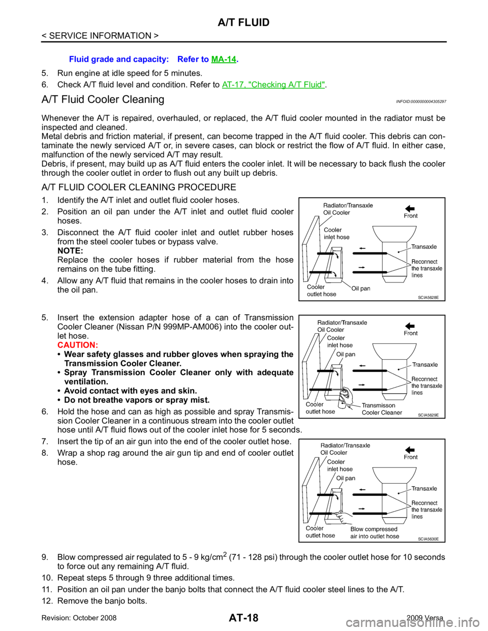
5. Insert the extension adapter hose of a can of Transmission
Cooler Cleaner (Nissan P/N 999MP-AM006) into the cooler out-
let hose.
CAUTION:
• Wear safety glasses and rubber gloves when spraying the Transmission Cooler Cleaner.
• Spray Transmission Cooler Cleaner only with adequate
ventilation.
• Avoid contact with eyes and skin.
• Do not breathe vapors or spray mist.
6. Hold the hose and can as high as possible and spray Transmis- sion Cooler Cleaner in a continuous stream into the cooler outlet
hose until A/T fluid flows out of t he cooler inlet hose for 5 seconds.
7. Insert the tip of an air gun into the end of the cooler outlet hose.
8. Wrap a shop rag around the air gun tip and end of cooler outlet hose.
9. Blow compressed air regulated to 5 - 9 kg/cm 2
(71 - 128 psi) through the cooler outlet hose for 10 seconds
to force out any remaining A/T fluid.
10. Repeat steps 5 through 9 three additional times.
11. Position an oil pan under the banjo bolts that connec t the A/T fluid cooler steel lines to the A/T.
12. Remove the banjo bolts. Fluid grade and capacity: Refer to
MA-14 .
SCIA5630E
Page 24 of 4331
A/T FLUID
AT-19
< SERVICE INFORMATION >
D
E
F
G H
I
J
K L
M A
B AT
N
O P
13. Flush each steel line from the cooler side back to
ward the A/T by spraying Transmission Cooler Cleaner
in a continuous stream for 5 seconds.
14. Blow compressed air regulated to 5 - 9 kg/cm 2
(71 - 128 psi) through each steel line from the cooler side
back toward the A/T for 10 seconds to force out any remaining A/T fluid.
15. Ensure all debris is removed from the steel cooler lines.
16. Ensure all debris is removed from the banjo bolts and fittings.
17. Perform "A/T FLUID COOL ER DIAGNOSIS PROCEDURE".
A/T FLUID COOLER DIAGNOSIS PROCEDURE NOTE:
Insufficient cleaning of the cooler inlet hose exte rior may lead to inaccurate debris identification.
1. Position an oil pan under the A/T inlet and outlet cooler hoses.
2. Clean the exterior and tip of the cooler inlet hose.
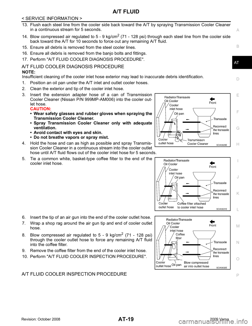
3. Insert the extension adapter hose of a can of Transmission Cooler Cleaner (Nissan P/N 999MP-AM006) into the cooler out-
let hose.
CAUTION:
• Wear safety glasses and rubber gloves when spraying the
Transmission Cooler Cleaner.
• Spray Transmission Cooler Cleaner only with adequate
ventilation.
• Avoid contact with eyes and skin.
• Do not breathe vapors or spray mist.
4. Hold the hose and can as high as possible and spray Transmis- sion Cooler Cleaner in a continuous stream into the cooler outlet
hose until A/T fluid flows out of t he cooler inlet hose for 5 seconds.
5. Tie a common white, basket-type coffee filter to the end of the cooler inlet hose.
6. Insert the tip of an air gun into the end of the cooler outlet hose.
7. Wrap a shop rag around the air gun tip and end of cooler outlet hose.
8. Blow compressed air regulated to 5 - 9 kg/cm 2
(71 - 128 psi)
through the cooler outlet hose to force any remaining A/T fluid
into the coffee filter.
9. Remove the coffee filter from the end of the cooler inlet hose.
10. Perform "A/T FLUID COOL ER INSPECTION PROCEDURE".
A/T FLUID COOLER INSPECTION PROCEDURE SCIA5629E
SCIA5631E
SCIA5632E
Page 28 of 4331
AT
N
O P
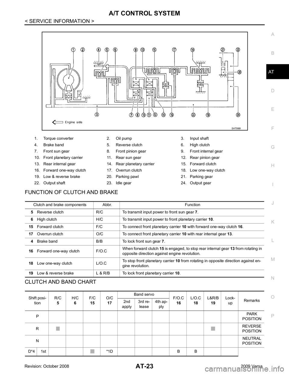
FUNCTION OF CLUTCH AND BRAKE
CLUTCH AND BAND CHART 1. Torque converter 2. Oil pump 3. Input shaft
4. Brake band 5. Reverse clutch 6. High clutch
7. Front sun gear 8. Front pinion gear 9. Front internal gear
10. Front planetary carrier 11. Rear sun gear 12. Rear pinion gear
13. Rear internal gear 14. Rear planetary carrier 15. Forward clutch
16. Forward one-way clutch 17. Overrun clutch 18. Low one-way clutch
19. Low & reverse brake 20. Parking pawl 21. Parking gear
22. Output shaft 23. Idle gear 24. Output gear Shift posi-
tion R/C
5 H/C
6 F/C
15 O/C
17 Band servo
F/O.C
16 L/O.C
18 L&R/B
19 Lock-
up Remarks
2nd
apply 3rd re-
lease 4th ap-
ply
P PARK
POSITION
R REVERSE
POSITION
N NEUTRAL
POSITION
D*4 1st *1D B B
Page 36 of 4331
AT
N
O P
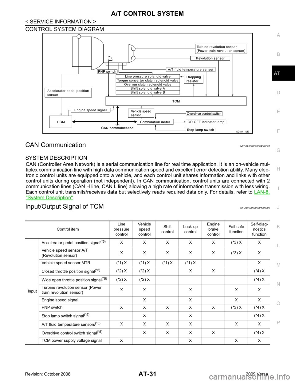
CONTROL SYSTEM DIAGRAM
CAN Communication INFOID:0000000004305301
SYSTEM DESCRIPTION CAN (Controller Area Network) is a serial communication li ne for real time application. It is an on-vehicle mul-
tiplex communication line with high data communication speed and excellent error detection ability. Many elec-
tronic control units are equipped onto a vehicle, and each control unit shares information and links with other
control units during operation (not independent). In CAN communication, control units are connected with 2
communication lines (CAN H line, CAN L line) allowing a high rate of information transmission with less wiring.
Each control unit transmits/receives data but selectively reads required data only. For details, refer to LAN-8," System Description " .
Input/Output Signal of TCM INFOID:0000000004305302
Page 38 of 4331
AT
N
O P
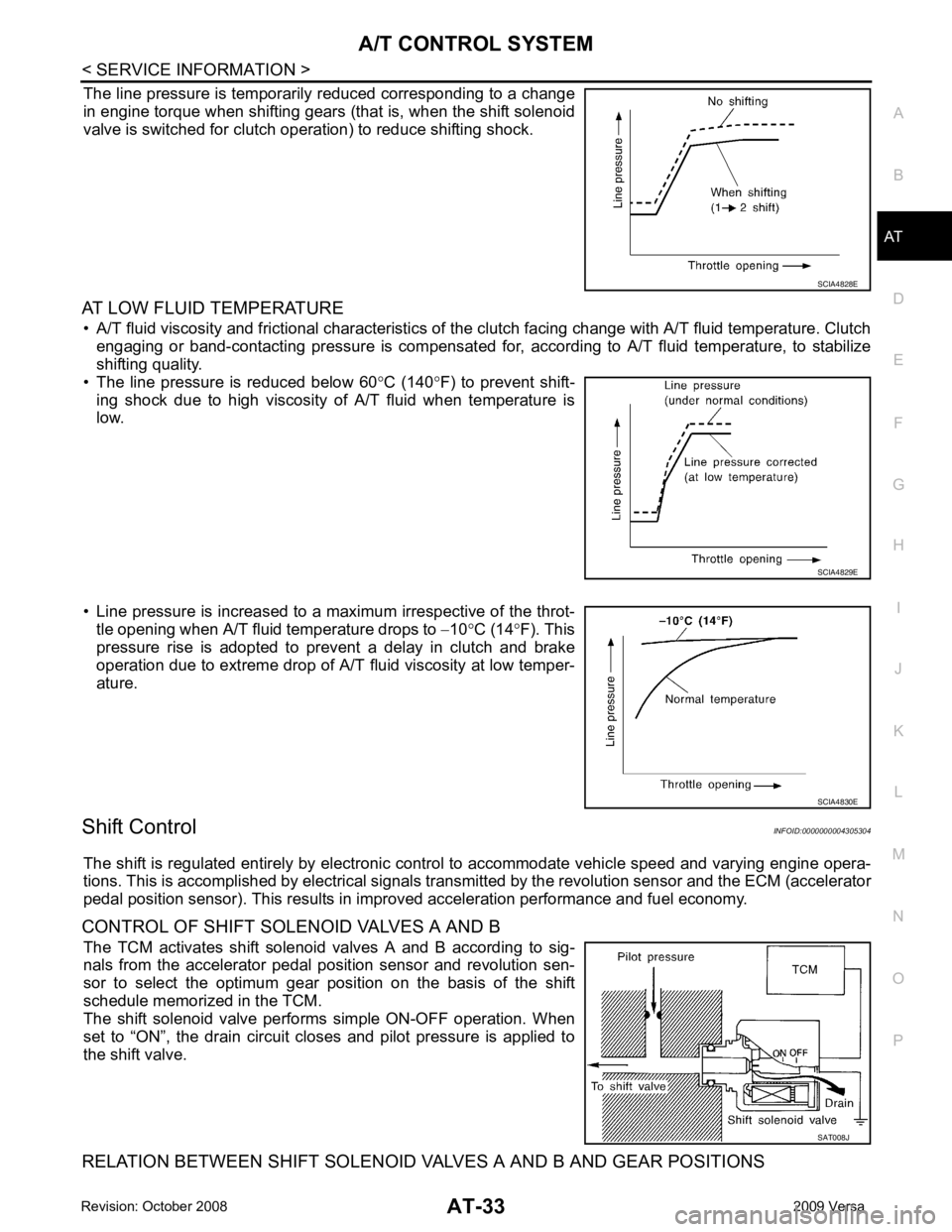
The line pressure is temporarily reduced corresponding to a change
in engine torque when shifting gears (that is, when the shift solenoid
valve is switched for clutch operation) to reduce shifting shock.
AT LOW FLUID TEMPERATURE • A/T fluid viscosity and frictional characteristics of t he clutch facing change with A/T fluid temperature. Clutch
engaging or band-contacting pressure is compensated for, according to A/T fluid temperature, to stabilize
shifting quality.
• The line pressure is reduced below 60 °C (140 °F) to prevent shift-
ing shock due to high viscosity of A/T fluid when temperature is
low.
• Line pressure is increased to a maximum irrespective of the throt- tle opening when A/T fluid temperature drops to −10 °C (14 °F). This
pressure rise is adopted to prevent a delay in clutch and brake
operation due to extreme drop of A/T fluid viscosity at low temper-
ature.
Shift Control INFOID:0000000004305304
The shift is regulated entirely by electronic cont rol to accommodate vehicle speed and varying engine opera-
tions. This is accomplished by electrical signals trans mitted by the revolution sensor and the ECM (accelerator
pedal position sensor). This results in improved acceleration performance and fuel economy.
CONTROL OF SHIFT SOLENOID VALVES A AND B The TCM activates shift solenoid valves A and B according to sig-
nals from the accelerator pedal position sensor and revolution sen-
sor to select the optimum gear pos ition on the basis of the shift
schedule memorized in the TCM.
The shift solenoid valve performs simple ON-OFF operation. When
set to “ON”, the drain circuit closes and pilot pressure is applied to
the shift valve.
RELATION BETWEEN SHIFT SOLENOID VALVES A AND B AND GEAR POSITIONS SAT008J
Page 42 of 4331

AT
N
O P
Control Valve
INFOID:0000000004305307
FUNCTION OF CONTROL VALVES
Centrifugal Cancel Mechanism INFOID:0000000004305308
FUNCTION The centrifugal cancel mechanism is a mechanism to c ancel the centrifugal hydraulic pressure instead of the
conventional check balls. It cancels the centrifugal hy draulic pressure which is generated as high clutch drum
rotates, and it allows for preventing high clutch from dragging and for providing stable high clutch piston press-
ing force in all revolution speeds.
STRUCTURE/OPERATION Valve name Function
Pressure regulator valve, plug and sleeve
plug Regulates oil discharged from the oil pump to provide optimum line pressure for all driving
conditions.
Pressure modifier valve and sleeve Used as a signal supplementary valve to the pressure regulator valve. Regulates pres- sure-modifier pressure (signal pressure) which controls optimum line pressure for all driv-
ing conditions.
Pilot valve Regulates line pressure to maintain a constant pilot pressure level which controls lock-up mechanism, overrun clutch, shift timing.
Accumulator control valve Regulates accumulator back-pressure to pressure suited to driving conditions.
Manual valve Directs line pressure to oil circuits corresponding to select positions. Hydraulic pressure drains when the shift lever is in Neutral.
Shift valve A Simultaneously switches three oil circuits using output pressure of shift solenoid valve A to meet driving conditions (vehicle speed, throttle opening, etc.).
Provides automatic downshifting and upshifting (1st → 2nd → 3rd → 4th gears/4th → 3rd
→ 2nd → 1st gears) in combination with shift valve B.
Shift valve B Simultaneously switches two oil circuits using output pressure of shift solenoid valve B in relation to driving conditions (vehicle speed, throttle opening, etc.).
Provides automatic downshifting and upshifting (1st → 2nd → 3rd → 4th gears/4th → 3rd
→ 2nd → 1st gears) in combination with shift valve A.
Overrun clutch control valve Switches hydraulic circuits to prevent engagement of the overrun clutch simultaneously with application of the brake band in D4. (Interlocking occurs if the overrun clutch engages
during D 4.)
1st reducing valve Reduces low & reverse brake pressure to dampen engine-brake shock when downshift- ing from the 1st position 12 to 1 1.
Overrun clutch reducing valve Reduces oil pressure directed to the overrun clutch and prevents engine-brake shock. In the 1st and 2nd positions, line pressure acts on the overrun clutch reducing valve to
increase the pressure-regulating point, with resultant engine brake capability.
Torque converter relief valve Prevents an excessive rise in torque converter pressure.
Torque converter clutch control valve, plug
and sleeve Activates or inactivates the lock-up function.
Also provides smooth lock-up through transient application and release of the lock-up
system.
1-2 accumulator valve and piston Lessens the shock find when the 2nd gear band servo contracts, and provides smooth shifting.
3-2 timing valve Switches the pace that oil pressure is released depending on vehicle speed; maximizes the high clutch release timing, and allows for soft downshifting.
Shuttle valve Determines if the overrun clutch solenoid valve should control the 3-2 timing valve or the overrun clutch control valve and switches between the two.
Cooler check valve At low speeds and with a small load when a little heat is generated, saves the volume of cooler flow, and stores the oil pressure for lock-up.
Page 57 of 4331
How to Perform Trouble Diagnosis for
Quick and Accurate Repair " .
NOTE:
Stall revolution is too high in “D”, “2”, or “1” position:
• Slippage occurs in 1st gear but not in 2nd and 3rd gears. ..... Low one-way clutch slippage
• Slippage occurs in the following gears:
1st through 3rd gears in “D” position and engine brake f unctions with OD OFF. (OD OFF indicator lamp is
on.)
1st and 2nd gears in “2” position and engine brake functions with accelerator pedal released (fully closed
throttle)...... Forwar d clutch or forward one-way clutch slippage
Stall revolution is too high in “R” position:
• Engine brake does not function in “1” posit ion. ..... Low & reverse brake slippage
• Engine brake functions in “1” position. ..... Reverse clutch slippage
Stall revolution with in specifications:
• Vehicle does not achieve speed of more than 80 km/h ( 50 MPH). ..... One-way clutch seizure in torque con-
verter housing
CAUTION:
Be careful because automatic flui d temperature increases abnormally:
• Slippage occurs in 3rd and 4th gears in “D” position. ..... High clutch slippage
• Slippage occurs in 2nd and 4th gears in “D” position. ..... Brake band slippage
• Engine brake does not function in 2nd and 3rd gears in “D” position, 2nd gear in “2” position, and 1st gear in “1” position with OD OFF. (OD OFF indicator lamp is on.) ..... Overrun clutch slippage
Stall revolution less than specifications:
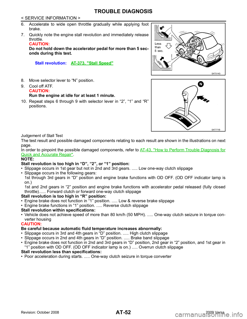
• Poor acceleration during starts. ..... One-way clutch seizure in torque converter Stall revolution:
AT-373, " Stall Speed "
SAT771B
Page 60 of 4331
AT
N
O P
Line Pressure
Judgement of Line Pressure Test
Road Test INFOID:0000000004305320
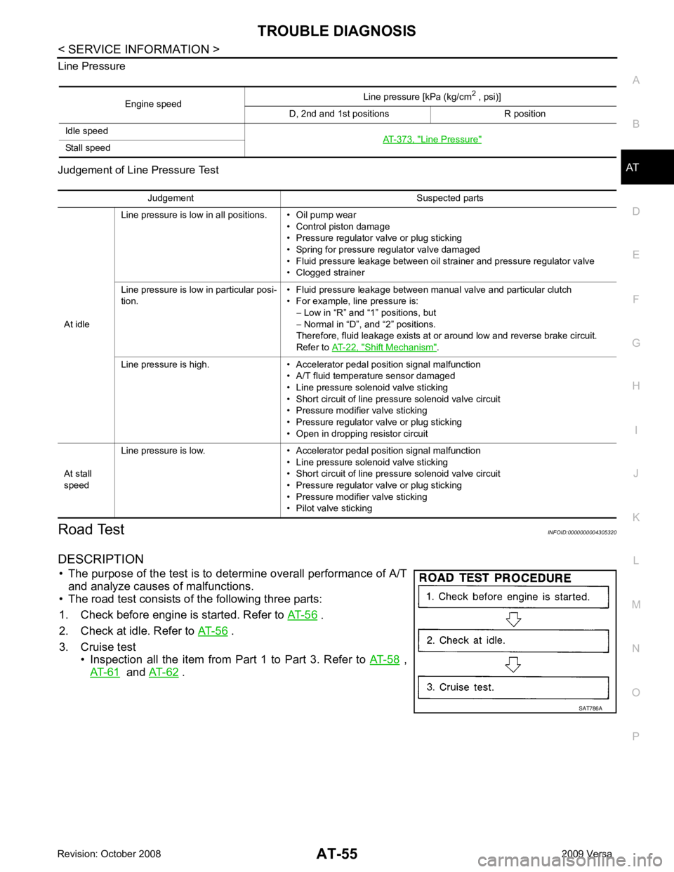
DESCRIPTION • The purpose of the test is to det ermine overall performance of A/T
and analyze causes of malfunctions.
• The road test consists of the following three parts:
1. Check before engine is started. Refer to AT-56 .
2. Check at idle. Refer to AT-56 .
3. Cruise test • Inspection all the item from Part 1 to Part 3. Refer to AT-58 ,
AT-61 and
AT-62 .
Engine speed
Line pressure [kPa (kg/cm
2
, psi)]
D, 2nd and 1st positions R position
Idle speed AT-373, " Line Pressure "
Stall speed
Judgement Suspected parts
At idle Line pressure is low in all positions. • Oil pump wear
• Control piston damage
• Pressure regulator valve or plug sticking
• Spring for pressure regulator valve damaged
• Fluid pressure leakage between oil strainer and pressure regulator valve
• Clogged strainer
Line pressure is low in particular posi-
tion. • Fluid pressure leakage between manual valve and particular clutch
• For example, line pressure is: − Low in “R” and “1 ” positions, but
− Normal in “D”, and “2” positions.
Therefore, fluid leakage exists at or around low and reverse brake circuit.
Refer to AT-22, " Shift Mechanism " .
Line pressure is high. • Accelerator pedal position signal malfunction • A/T fluid temperature sensor damaged
• Line pressure solenoid valve sticking
• Short circuit of line pressure solenoid valve circuit
• Pressure modifier valve sticking
• Pressure regulator valve or plug sticking
• Open in dropping resistor circuit
At stall
speed Line pressure is low. • Accelerator pedal position signal malfunction
• Line pressure solenoid valve sticking
• Short circuit of line pressure solenoid valve circuit
• Pressure regulator valve or plug sticking
• Pressure modifier valve sticking
• Pilot valve sticking
Page 70 of 4331
AT
N
O P
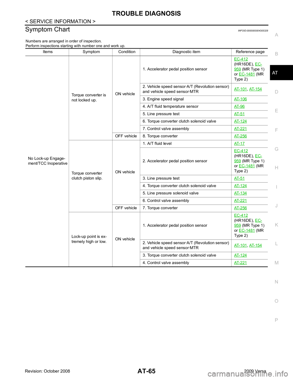
Symptom Chart
INFOID:0000000004305328
Numbers are arranged in order of inspection.
Perform inspections starting with number one and work up.
Items Symptom Condition Diagnostic item Reference page
No Lock-up Engage-
ment/TCC Inoperative Torque converter is
not locked up. ON vehicle1. Accelerator pedal position sensor
EC-412
(HR16DE), EC- 959 (MR Type 1)
or EC-1481 (MR
Type 2)
2. Vehicle speed sensor·A/T (Revolution sensor)
and vehicle speed sensor·MTR AT-101 ,
AT-154 3. Engine speed signal
AT-106 4. A/T fluid temperature sensor
AT-96 5. Line pressure test
AT-51 6. Torque converter clutch solenoid valve
AT-124 7. Control valve assembly
AT-221 OFF vehicle 8. Torque converter
AT-256Torque converter
clutch piston slip. ON vehicle1. A/T fluid level
AT-17 2. Accelerator pedal position sensor
EC-412
(HR16DE), EC- 959 (MR Type 1)
or EC-1481 (MR
Type 2)
3. Line pressure test AT-51 4. Torque converter clutch solenoid valve
AT-124 5. Line pressure solenoid valve
AT-134 6. Control valve assembly
AT-221 OFF vehicle 7. Torque converter
AT-256Lock-up point is ex-
tremely high or low. ON vehicle1. Accelerator pedal position sensor
EC-412
(HR16DE), EC- 959 (MR Type 1)
or EC-1481 (MR
Type 2)
2. Vehicle speed sensor·A/T (Revolution sensor)
and vehicle speed sensor·MTR AT-101 ,
AT-154 3. Torque converter clutch solenoid valve
AT-124 4. Control valve assembly
AT-221