brakes NISSAN LATIO 2010 Service User Guide
[x] Cancel search | Manufacturer: NISSAN, Model Year: 2010, Model line: LATIO, Model: NISSAN LATIO 2010Pages: 3745, PDF Size: 73.67 MB
Page 333 of 3745

AT-316
< SERVICE INFORMATION >
REPAIR FOR COMPONENT PARTS
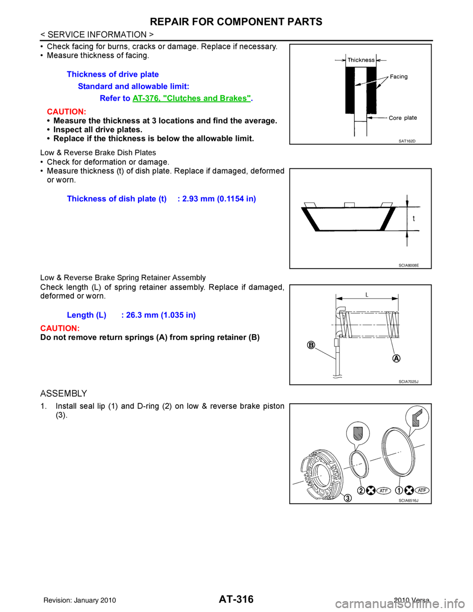
• Check facing for burns, cracks or damage. Replace if necessary.
• Measure thickness of facing.CAUTION:
• Measure the thickness at 3 locations and find the average.
• Inspect all drive plates.
• Replace if the thickness is below the allowable limit.
Low & Reverse Brake Dish Plates
• Check for deformation or damage.
• Measure thickness (t) of dish pl ate. Replace if damaged, deformed
or worn.
Low & Reverse Brake Spring Retainer Assembly
Check length (L) of spring retainer assembly. Replace if damaged,
deformed or worn.
CAUTION:
Do not remove return springs (A ) from spring retainer (B)
ASSEMBLY
1. Install seal lip (1) and D-ring (2) on low & reverse brake piston
(3).Thickness of drive plate
Standard and allowable limit: Refer to AT-376, "
Clutches and Brakes".
SAT162D
Thickness of dish plate (t) : 2.93 mm (0.1154 in)
SCIA8008E
Length (L) : 26.3 mm (1.035 in)
SCIA7025J
SCIA6516J
Revision: January 20102010 Versa
Page 335 of 3745

AT-318
< SERVICE INFORMATION >
REPAIR FOR COMPONENT PARTS
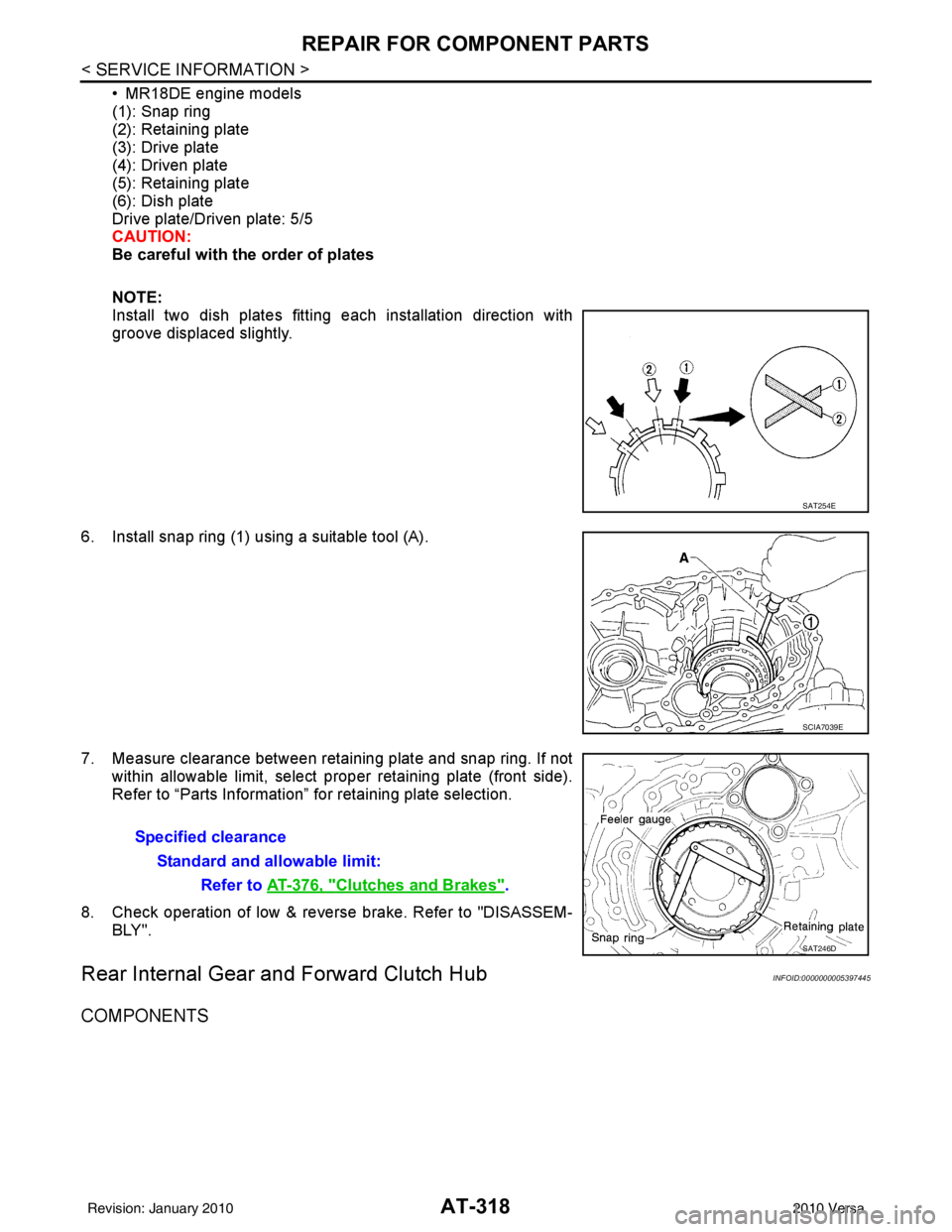
• MR18DE engine models
(1): Snap ring
(2): Retaining plate
(3): Drive plate
(4): Driven plate
(5): Retaining plate
(6): Dish plate
Drive plate/Driven plate: 5/5
CAUTION:
Be careful with the order of plates
NOTE:
Install two dish plates fitting each installation direction with
groove displaced slightly.
6. Install snap ring (1) using a suitable tool (A).
7. Measure clearance between retaining plate and snap ring. If not within allowable limit, select proper retaining plate (front side).
Refer to “Parts Information” for retaining plate selection.
8. Check operation of low & revers e brake. Refer to "DISASSEM-
BLY".
Rear Internal Gear and Forward Clutch HubINFOID:0000000005397445
COMPONENTS
SAT254E
SCIA7039E
Specified clearance
Standard and allowable limit: Refer to AT-376, "
Clutches and Brakes".
SAT246D
Revision: January 20102010 Versa
Page 393 of 3745

AT-376
< SERVICE INFORMATION >
SERVICE DATA AND SPECIFICATIONS (SDS)
Unit: mm (in)
AccumulatorINFOID:0000000005397462
RETURN SPRINGS
Unit: mm (in)
Unit: mm (in)
O-RINGS
Unit: mm (in)
Clutches and BrakesINFOID:0000000005397463
REVERSE CLUTCH
Locationspring designation Free length (l) Outer diameter (D)
Upper body L14 Pilot valve spring
38.98 (1.5346)8.9 (0.350)
L15 1–2 accumulator valve spring
20.5 (0.807)6.95 (0.2736)
1–2 accumulator piston spring 55.66 (2.1913)19.5 (0.768)
L16 1st reducing valve spring 27.0 (1.063)7.0 (0.276)
L17 3–2 timing valve spring 23.0 (0.906)6.65 (0.2618)
L18 Overrun clutch reducing valve spring37.5 (1.476)7.0 (0.276)
L19 Torque converter relief valve spring 33.3 (1.311)9.0 (0.354)
L20 Torque converter clutch control valve spring 53.01 (2.0870)6.5 (0.256)
L21 Cooler check valve spring 28.04 (1.1039)7.15 (0.2815)
Lower body L3 Pressure regulator valve spring
45.0 (1.772)15.0 (0.591)
L4 Overrun clutch control valve spring 21.7 (0.854)7.0 (0.276)
L5 Accumulator control valve spring 22.0 (0.866)6.5 (0.256)
L6 Shift valve A spring 21.7 (0.854)7.0 (0.276)
L7 Shuttle valve spring 51.0 (2.008)5.65 (0.2224)
L12 Shift valve B spring 21.7 (0.854)7.0 (0.276)
L13 Pressure modifier valve spring
32.0 (1.260)6.9 (0.272)
Pressure modifier piston spring 30.5 (1.201)9.8 (0.386)
— Line pressure relief valve spring 17.02 (0.6701)8.0 (0.315)
— Torque converter pressure holding spring 9.0 (0.354)7.3 (0.287)
Location Free length (L1)
Servo release accumulator 62.8 (2.472)
LocationLength (L2)
N-D accumulator 46.5 (1.831)
LocationInner diameter (Small) Inner diameter (Large)
Servo release accumulator 26.9 (1.059)44.2 (1.740)
N-D accumulator 34.6 (1.362)39.4 (1.551)
Number of drive plates 2
Number of driven plates 2
Drive plate thickness [mm (in)] Standard
2.0 (0.079)
Allowable limit 1.8 (0.071)
Driven plate thickness [mm (in)] Standard 2.0 (0.079)
Clearance [mm (in)] Standard
0.5 - 0.8 (0.020 - 0.031)
Allowable limit 1.2 (0.047)
Revision: January 20102010 Versa
Page 849 of 3745

BR-1
BRAKES
C
DE
G H
I
J
K L
M
SECTION BR
A
B
BR
N
O P
CONTENTS
BRAKE SYSTEM
SERVICE INFORMATION .. ..........................2
PRECAUTIONS .............................................. .....2
Precaution for Supplemental Restraint System
(SRS) "AIR BAG" and "SEAT BELT PRE-TEN-
SIONER" ............................................................. ......
2
Precaution Necessary for Steering Wheel Rota-
tion After Battery Disconnect ............................... ......
2
Precaution for Brake System ....................................3
PREPARATION ...................................................4
Special Service Tool ........................................... ......4
Commercial Service Tool ..........................................4
NOISE, VIBRATION AND HARSHNESS
(NVH) TROUBLESHOOTING .............................
5
NVH Troubleshooting Chart ................................ ......5
BRAKE PEDAL .............................................. .....6
Inspection and Adjustment .................................. ......6
Removal and Installation ...........................................7
BRAKE FLUID ................................................ .....9
On Board Inspection ........................................... ......9
Drain and Refill ..........................................................9
Bleeding Brake System .............................................9
BRAKE TUBE AND HOSE ................................11
Hydraulic Circuit .................................................. ....11
Front Brake Tube and Hose ....................................12
Rear Brake Tube and Hose ....................................12
Inspection After Installation .....................................13
DUAL PROPORTIONING VALVE .....................14
Removal and Installation .........................................14
Inspection ............................................................ ....14
BRAKE MASTER CYLINDER ........................ ....15
On-Board Inspection ........................................... ....15
Removal and Installation ..................................... ....15
Disassembly and Assembly .....................................16
BRAKE BOOSTER ...........................................20
On Board Inspection ............................................ ....20
Removal and Installation .........................................21
VACUUM LINES ...............................................23
Component ..............................................................23
Removal and Installation .........................................23
Inspection ................................................................23
FRONT DISC BRAKE .......................................25
On Board Inspection ............................................ ....25
Component ..............................................................25
Removal and Installation of Brake Pad ...................26
Removal and Installation of Brake Caliper Assem-
bly ........................................................................ ....
30
Disassembly and Assembly of Brake Caliper As-
sembly .....................................................................
31
Brake Burnishing Procedure ....................................34
REAR DRUM BRAKE .......................................35
Component .......................................................... ....35
Removal and Installation of Drum Brake Assembly
....
36
Removal and Installation of Wheel Cylinder ............39
Disassembly and Assembly of Wheel Cylinder .......39
SERVICE DATA AND SPECIFICATIONS
(SDS) .................................................................
40
General Specification ..............................................40
Brake Pedal .............................................................41
Check Valve ............................................................41
Brake Booster ..........................................................42
Front Disc Brake ......................................................42
Rear Drum Brake .....................................................42
Revision: January 20102010 Versa
Page 862 of 3745

BR-14
< SERVICE INFORMATION >
DUAL PROPORTIONING VALVE
DUAL PROPORTIONING VALVE
Removal and InstallationINFOID:0000000005396987
Removal
1. Remove cowl top . Refer to EI-22, "Removal and Installation".
2. Disconnect brake lines from dual proportioning valve. • Mark brake lines for installation.
3. Remove dual proportioning valve bolt and dual proportioning valve.
4. Remove two bolts and bracket.
Installation
Installation is in the reverse order of removal.
• When installing brake lines to the dual proportioning valve, tighten to specifications. Refer to BR-11,
"Hydraulic Circuit".
InspectionINFOID:0000000005396988
CAUTION:
• Carefully monitor brake fluid level at master cylinder.
• Use the recommended new brake fluid. Refer to MA-14, "
Fluids and Lubricants".
• Be careful not to splash brake fluid on painted areas; it may cause paint damage. If brake fluid is
splashed on paint areas, wash it away with water immediately.
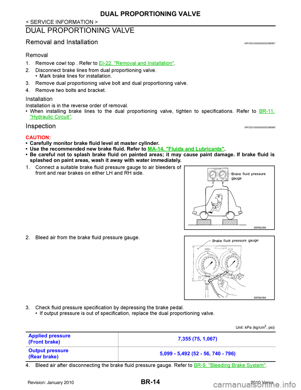
1. Connect a suitable brake fluid pressure gauge to air bleeders of front and rear brakes on either LH and RH side.
2. Bleed air from the brake fluid pressure gauge.
3. Check fluid pressure specific ation by depressing the brake pedal.
• If output pressure is out of specification, replace the dual proportioning valve.
Unit: kPa (kg/cm2, psi)
4. Bleed air after disconnecting the brake fluid pressure gauge. Refer to BR-9, "Bleeding Brake System".
SBR822BA
SBR823BA
Applied pressure
(Front brake) 7,355 (75, 1,067)
Output pressure
(Rear brake) 5,099 - 5,492 (52 - 56, 740 - 796)
Revision: January 20102010 Versa
Page 876 of 3745

BR-28
< SERVICE INFORMATION >
FRONT DISC BRAKE
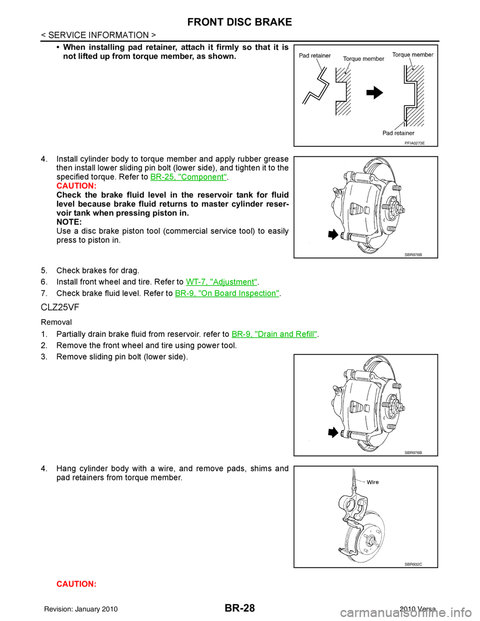
• When installing pad retainer, attach it firmly so that it isnot lifted up from torque member, as shown.
4. Install cylinder body to torque member and apply rubber grease then install lower sliding pin bolt (lower side), and tighten it to the
specified torque. Refer to BR-25, "
Component".
CAUTION:
Check the brake fluid level in the reservoir tank for fluid
level because brake fluid returns to master cylinder reser-
voir tank when pressing piston in.
NOTE:
Use a disc brake piston tool (commercial service tool) to easily
press to piston in.
5. Check brakes for drag.
6. Install front wheel and tire. Refer to WT-7, "
Adjustment".
7. Check brake fluid level. Refer to BR-9, "
On Board Inspection".
CLZ25VF
Removal
1. Partially drain brake fluid from reservoir. refer to BR-9, "Drain and Refill".
2. Remove the front wheel and tire using power tool.
3. Remove sliding pin bolt (lower side).
4. Hang cylinder body with a wire, and remove pads, shims and pad retainers from torque member.
CAUTION:
PFIA0273E
SBR976B
SBR976B
SBR932C
Revision: January 20102010 Versa
Page 891 of 3745

BRC-1
BRAKES
C
DE
G H
I
J
K L
M
SECTION BRC
A
B
BRC
N
O P
CONTENTS
BRAKE CONTROL SYSTEM
ABS
SERVICE INFORMATION .. ..........................
3
PRECAUTIONS .............................................. .....3
Precaution for Supplemental Restraint System
(SRS) "AIR BAG" and "SEAT BELT PRE-TEN-
SIONER" ............................................................. ......
3
Precaution Necessary for Steering Wheel Rota-
tion After Battery Disconnect ............................... ......
3
Precaution for Brake System ....................................4
Precaution for Brake Control .....................................4
Precaution for CAN System ................................ ......4
PREPARATION ...................................................6
Special Service Tool ........................................... ......6
Commercial Service Tool ..........................................6
SYSTEM DESCRIPTION .....................................7
System Component ............................................. ......7
ABS Function ............................................................7
EBD Function ............................................................7
Fail-Safe Function .....................................................7
Hydraulic Circuit Diagram .........................................8
CAN COMMUNICATION ................................ .....9
System Description ............................................. ......9
TROUBLE DIAGNOSIS .....................................10
How to Perform Trouble Diagnosis for Quick and
Accurate Repair ......................................................
10
Component Parts and Harness Connector Loca-
tion ...................................................................... ....
13
Schematic ...............................................................14
Wiring Diagram - ABS - ...........................................15
Basic Inspection .................................................. ....18
Warning Lamp and Indicator Timing .......................19
Control Unit Input/Output Signal Standard ..............19
CONSULT-III Function (ABS) .................................20
TROUBLE DIAGNOSIS FOR SELF-DIAG-
NOSTIC ITEMS ..................................................
26
Wheel Sensor System ......................................... ....26
ABS Control Unit Inspection ....................................27
Solenoid Valve System Inspection ..........................27
Actuator Motor, Motor Relay, and Circuit Inspec-
tion ....................................................................... ....
28
ABS Control Unit Power and Ground Systems In-
spection ...................................................................
29
CAN Communication System Inspection .................30
TROUBLE DIAGNOSES FOR SYMPTOMS .....31
ABS Works Frequently ............................................31
Unexpected Pedal Action ........................................31
Long Stopping Distance ..........................................32
ABS Does Not Work ................................................32
Pedal Vibration or ABS Operation Noise .................32
WHEEL SENSORS ...........................................34
Removal and Installation ..................................... ....34
SENSOR ROTOR ..............................................36
Removal and Installation .........................................36
ACTUATOR AND ELECTRIC UNIT (ASSEM-
BLY) ..................................................................
37
Removal and Installation .........................................37
VDC/TCS/ABS
SERVICE INFORMATION .. .........................
39
PRECAUTIONS .................................................39
Precaution for Supplemental Restraint System
(SRS) "AIR BAG" and "SEAT BELT PRE-TEN-
SIONER" ............................................................. ....
39
Precaution Necessary for Steering Wheel Rota-
tion After Battery Disconnect ...................................
39
Precaution for Brake System ...................................40
Precaution for Brake Control ...................................40
Precaution for CAN System .....................................41
PREPARATION .................................................42
Special Service Tool ................................................42
Commercial Service Tool ........................................42
Revision: January 20102010 Versa
Page 991 of 3745
![NISSAN LATIO 2010 Service User Guide OVERHEATING CAUSE ANALYSISCO-9
< SYMPTOM DIAGNOSIS > [HR16DE]
C
D
E
F
G H
I
J
K L
M A
CO
NP
O
Except cool-
ing system
parts mal-
function —
Overload on engine Abusive driving
High engine rpm under NISSAN LATIO 2010 Service User Guide OVERHEATING CAUSE ANALYSISCO-9
< SYMPTOM DIAGNOSIS > [HR16DE]
C
D
E
F
G H
I
J
K L
M A
CO
NP
O
Except cool-
ing system
parts mal-
function —
Overload on engine Abusive driving
High engine rpm under](/img/5/57358/w960_57358-990.png)
OVERHEATING CAUSE ANALYSISCO-9
< SYMPTOM DIAGNOSIS > [HR16DE]
C
D
E
F
G H
I
J
K L
M A
CO
NP
O
Except cool-
ing system
parts mal-
function —
Overload on engine Abusive driving
High engine rpm under no
load
Driving in low gear for ex-
tended time
Driving at extremely high
speed
Power train system mal-
function
—
Installed improper size
wheels and tires
Dragging brakes
Improper ignition timing
Blocked or restricted air
flow Blocked bumper
Installed front bumper fas-
cia cover
—
Blocked radiator grille Mud contamination or paper
clogging
Blocked radiator Blocked air flow
Blocked condenser
Installed large fog lamp
Symptom
Check items
Revision: January 20102010 Versa
Page 1016 of 3745
![NISSAN LATIO 2010 Service User Guide CO-34
< SERVICE INFORMATION >[MR18DE]
OVERHEATING CAUSE ANALYSIS
Except cool-
ing system
parts mal-
function—
Overload on engine Abusive driving
High engine rpm under no
load
Driving in low gear f NISSAN LATIO 2010 Service User Guide CO-34
< SERVICE INFORMATION >[MR18DE]
OVERHEATING CAUSE ANALYSIS
Except cool-
ing system
parts mal-
function—
Overload on engine Abusive driving
High engine rpm under no
load
Driving in low gear f](/img/5/57358/w960_57358-1015.png)
CO-34
< SERVICE INFORMATION >[MR18DE]
OVERHEATING CAUSE ANALYSIS
Except cool-
ing system
parts mal-
function—
Overload on engine Abusive driving
High engine rpm under no
load
Driving in low gear for ex-
tended time
Driving at extremely high
speed
Power train system mal-
function
—
Installed improper size
wheels and tires
Dragging brakes
Improper ignition timing
Blocked or restricted air
flow Blocked bumper
Installed front bumper fas-
cia cover
—
Blocked radiator grille Mud contamination or paper
clogging
Blocked radiator Blocked air flow
Blocked condenser
Installed large fog lamp
Symptom
Check items
Revision: January 20102010 Versa
Page 1044 of 3745
![NISSAN LATIO 2010 Service User Guide PRECAUTIONSCVT-11
< SERVICE INFORMATION > [RE0F08B]
D
E
F
G H
I
J
K L
M A
B
CVT
N
O P
• When connecting or disconnecting pin connectors into or
from TCM, take care not to damage pin terminals (bend NISSAN LATIO 2010 Service User Guide PRECAUTIONSCVT-11
< SERVICE INFORMATION > [RE0F08B]
D
E
F
G H
I
J
K L
M A
B
CVT
N
O P
• When connecting or disconnecting pin connectors into or
from TCM, take care not to damage pin terminals (bend](/img/5/57358/w960_57358-1043.png)
PRECAUTIONSCVT-11
< SERVICE INFORMATION > [RE0F08B]
D
E
F
G H
I
J
K L
M A
B
CVT
N
O P
• When connecting or disconnecting pin connectors into or
from TCM, take care not to damage pin terminals (bend or
break).
When connecting pin connectors make sure that there are not
any bends or breaks on TCM pin terminal.
• Before replacing TCM, perform TCM input/output signal
inspection and make sure whether TCM functions properly or
not. CVT-46, "
TCM Terminal and Reference Value".
• After performing each TROUBL E DIAGNOSIS, perform “DTC
Confirmation Procedure”.
If the repair is completed the DTC should not be displayed in
the “DTC Confirmation Procedure”.
• Always use the specified br and of CVT fluid. Refer to MA-14, "
Flu-
ids and Lubricants".
• Use lint-free paper, not cloth rags, during work.
• After replacing the CVT fluid, dispose of the waste oil using the methods prescribed by law, ordinance, etc.
Service Notice or PrecautionINFOID:0000000005397764
CVT FLUID COOLER SERVICE
If CVT fluid contains friction material (clutches, brakes , etc.), or if an CVT is replaced, inspect and clean the
CVT fluid cooler mounted in the radiator or replace the radiator. Flush cooler lines using cleaning solvent and
compressed air after repair. For CVT fluid cooler cleaning procedure, refer to CVT-15, "
CVT Fluid Cooler
Cleaning". For radiator replacement, refer to CO-40.
OBD-II SELF-DIAGNOSIS
• CVT self-diagnosis is performed by the TCM in combination with the ECM. The results can be read through
the blinking pattern of the malfunction indi cator lamp (MIL). Refer to the table on CVT-48, "
CONSULT-III
Function (TRANSMISSION)" for the indicator used to display each self-diagnostic result.
• The self-diagnostic results indicated by the MIL are automatically stored in both the ECM and TCM memo- ries.
Always perform the procedure on CVT-27, "
OBD-II Diagnostic Trouble Code (DTC)" to complete the
repair and avoid unnecessary blinking of the MIL.
For details of OBD-II, refer to EC-541, "
Introduction".
• Certain systems and components, especially those re lated to OBD, may use the new style slide-lock-
ing type harness connector. For description and how to disconnect, refer to PG-66
.
ATFTEMP COUNT Conversion Table INFOID:0000000005709762
SEF291H
MEF040DA
SEF217U
Revision: January 20102010 Versa