Lighting NISSAN LATIO 2010 Service Owner's Manual
[x] Cancel search | Manufacturer: NISSAN, Model Year: 2010, Model line: LATIO, Model: NISSAN LATIO 2010Pages: 3745, PDF Size: 73.67 MB
Page 736 of 3745
VEHICLE SECURITY (THEFT WARNING) SYSTEMBL-227
< SERVICE INFORMATION >
C
DE
F
G H
J
K L
M A
B
BL
N
O P
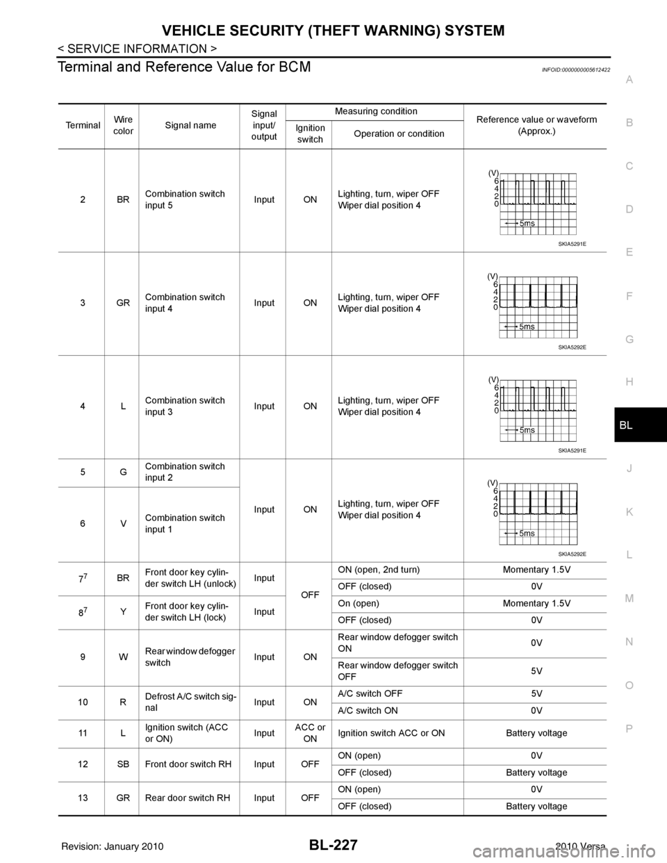
Terminal and Reference Value for BCMINFOID:0000000005612422
Te r m i n a l Wire
color Signal name Signal
input/
output Measuring condition
Reference value or waveform
(Approx.)
Ignition
switch Operation or condition
2BR Combination switch
input 5
Input ONLighting, turn, wiper OFF
Wiper dial position 4
3GR Combination switch
input 4 Input ONLighting, turn, wiper OFF
Wiper dial position 4
4L Combination switch
input 3
Input ONLighting, turn, wiper OFF
Wiper dial position 4
5G Combination switch
input 2
Input ONLighting, turn, wiper OFF
Wiper dial position 4
6V Combination switch
input 1
7
7BR Front door key cylin-
der switch LH (unlock) Input
OFFON (open, 2nd turn)
Momentary 1.5V
OFF (closed) 0V
8
7Y Front door key cylin-
der switch LH (lock) InputOn (open)
Momentary 1.5V
OFF (closed) 0V
9W Rear window defogger
switch Input ONRear window defogger switch
ON
0V
Rear window defogger switch
OFF 5V
10 R Defrost A/C switch sig-
nal
Input ONA/C switch OFF
5V
A/C switch ON 0V
11 L Ignition switch (ACC
or ON) InputACC or
ON Ignition switch ACC or ON
Battery voltage
12 SB Front door switch RH Input OFF ON (open)
0V
OFF (closed) Battery voltage
13 GR Rear door switch RH Input OFF ON (open)
0V
OFF (closed) Battery voltage
SKIA5291E
SKIA5292E
SKIA5291E
SKIA5292E
Revision: January 20102010 Versa
Page 738 of 3745
VEHICLE SECURITY (THEFT WARNING) SYSTEMBL-229
< SERVICE INFORMATION >
C
DE
F
G H
J
K L
M A
B
BL
N
O P
301LG Back door/trunk out-
put Output —Back door open (switch
closed)
0V
Back door closed (switch
open) 5V
30
3LG Back door opener
switch
Input —All doors locked (SW OFF)
Battery voltage
All doors unlocked (SW ON) 0V
30
4V Trunk lid opener
switch
Input —All doors locked (SW OFF)
Battery voltage
All doors unlocked (SW ON) 0V
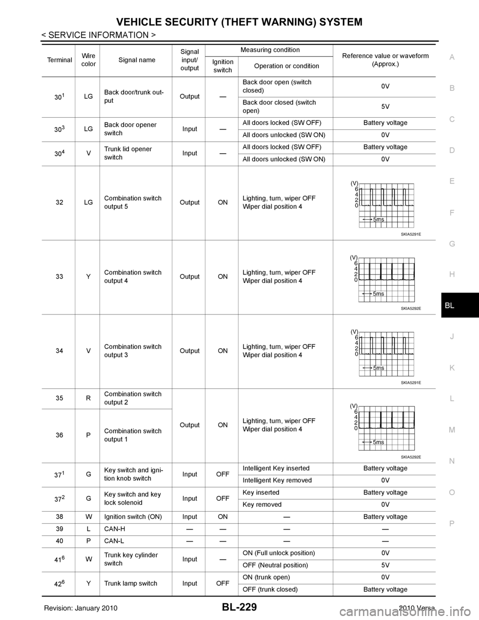
32 LG Combination switch
output 5 Output ONLighting, turn, wiper OFF
Wiper dial position 4
33 Y Combination switch
output 4 Output ON
Lighting, turn, wiper OFF
Wiper dial position 4
34 V Combination switch
output 3
Output ONLighting, turn, wiper OFF
Wiper dial position 4
35 R Combination switch
output 2
Output ONLighting, turn, wiper OFF
Wiper dial position 4
36 P Combination switch
output 1
37
1G Key switch and igni-
tion knob switch Input OFFIntelligent Key inserted
Battery voltage
Intelligent Key removed 0V
37
2G Key switch and key
lock solenoid Input OFFKey inserted
Battery voltage
Key removed 0V
38 W Ignition switch (ON) Input ON —Battery voltage
39 L CAN-H — —— —
40 P CAN-L — —— —
41
6W Trunk key cylinder
switch
Input —ON (Full unlock position)
0V
OFF (Neutral position) 5V
42
6Y Trunk lamp switch Input OFF ON (trunk open)
0V
OFF (trunk closed) Battery voltage
Te r m i n a l
Wire
color Signal name Signal
input/
output Measuring condition
Reference value or waveform
(Approx.)
Ignition
switch Operation or condition
SKIA5291E
SKIA5292E
SKIA5291E
SKIA5292E
Revision: January 20102010 Versa
Page 751 of 3745
BL-242
< SERVICE INFORMATION >
VEHICLE SECURITY (THEFT WARNING) SYSTEM
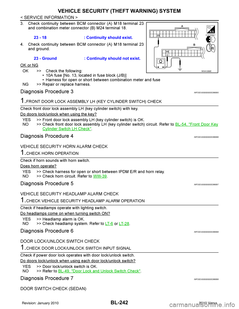
3. Check continuity between BCM connector (A) M18 terminal 23
and combination meter connector (B) M24 terminal 18.
4. Check continuity between BCM connector (A) M18 terminal 23 and ground.
OK or NG
OK >> Check the following: • 10A fuse [No. 13, located in fuse block (J/B)]
• Harness for open or short between combination meter and fuse
NG >> Repair or replace harness.
Diagnosis Procedure 3INFOID:0000000005396695
1.FRONT DOOR LOCK ASSEMBLY LH (KEY CYLINDER SWITCH) CHECK
Check front door lock assembly LH (key cylinder switch) with key.
Do doors lock/unlock when using the key?
YES >> Front door lock assembly LH (key cylinder switch) is OK.
NO >> Check front door lock assembly LH (key cylinder switch) circuit. Refer to BL-54, "
Front Door Key
Cylinder Switch LH Check".
Diagnosis Procedure 4INFOID:0000000005396696
VEHICLE SECURITY HORN ALARM CHECK
1.CHECK HORN OPERATION
Check if horn sounds with horn switch.
Does horn operate?
YES >> Check harness for open or short between IPDM E/R and horn relay.
NO >> Check horn circuit. Refer to WW-39
.
Diagnosis Procedure 5INFOID:0000000005396697
VEHICLE SECURITY HEADLAMP ALARM CHECK
1.CHECK VEHICLE SECURITY HEADLAMP ALARM OPERATION
Check if headlamps operate with lighting switch.
Do headlamps come on when turning switch ON?
YES >> Headlamp alarm is OK.
NO >> Check headlamp system. Refer to LT- 6
or LT- 2 8.
Diagnosis Procedure 6INFOID:0000000005396698
DOOR LOCK/UNLOCK SWITCH CHECK
1.CHECK DOOR LOCK/UNLOCK SWITCH INPUT SIGNAL
Check if power door lock operates with door lock/unlock switch.
Do doors lock/unlock when using each door lock/unlock switch?
YES >> Door lock/unlock switch is OK.
NO >> Refer to BL-49, "
Door Lock and Unlock Switch Check".
Diagnosis Procedure 7INFOID:0000000005396699
DOOR SWITCH CHECK (SEDAN)
23 - 18 : Continuity should exist.
23 - Ground : Continuity should not exist.
WIIA1269E
Revision: January 20102010 Versa
Page 761 of 3745
BL-252
< SERVICE INFORMATION >
NATS (NISSAN ANTI-THEFT SYSTEM)
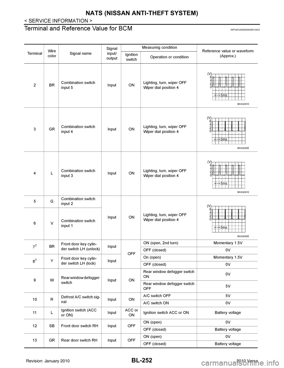
Terminal and Reference Value for BCM
INFOID:0000000005612423
Te r m i n a l Wire
color Signal name Signal
input/
output Measuring condition
Reference value or waveform
(Approx.)
Ignition
switch Operation or condition
2BR Combination switch
input 5
Input ONLighting, turn, wiper OFF
Wiper dial position 4
3GR Combination switch
input 4 Input ONLighting, turn, wiper OFF
Wiper dial position 4
4L Combination switch
input 3
Input ONLighting, turn, wiper OFF
Wiper dial position 4
5G Combination switch
input 2
Input ONLighting, turn, wiper OFF
Wiper dial position 4
6V Combination switch
input 1
7
7BR Front door key cylin-
der switch LH (unlock) Input
OFFON (open, 2nd turn)
Momentary 1.5V
OFF (closed) 0V
8
7Y Front door key cylin-
der switch LH (lock) InputOn (open)
Momentary 1.5V
OFF (closed) 0V
9W Rear window defogger
switch Input ONRear window defogger switch
ON
0V
Rear window defogger switch
OFF 5V
10 R Defrost A/C switch sig-
nal
Input ONA/C switch OFF
5V
A/C switch ON 0V
11 L Ignition switch (ACC
or ON) InputACC or
ON Ignition switch ACC or ON
Battery voltage
12 SB Front door switch RH Input OFF ON (open)
0V
OFF (closed) Battery voltage
13 GR Rear door switch RH Input OFF ON (open)
0V
OFF (closed) Battery voltage
SKIA5291E
SKIA5292E
SKIA5291E
SKIA5292E
Revision: January 20102010 Versa
Page 763 of 3745
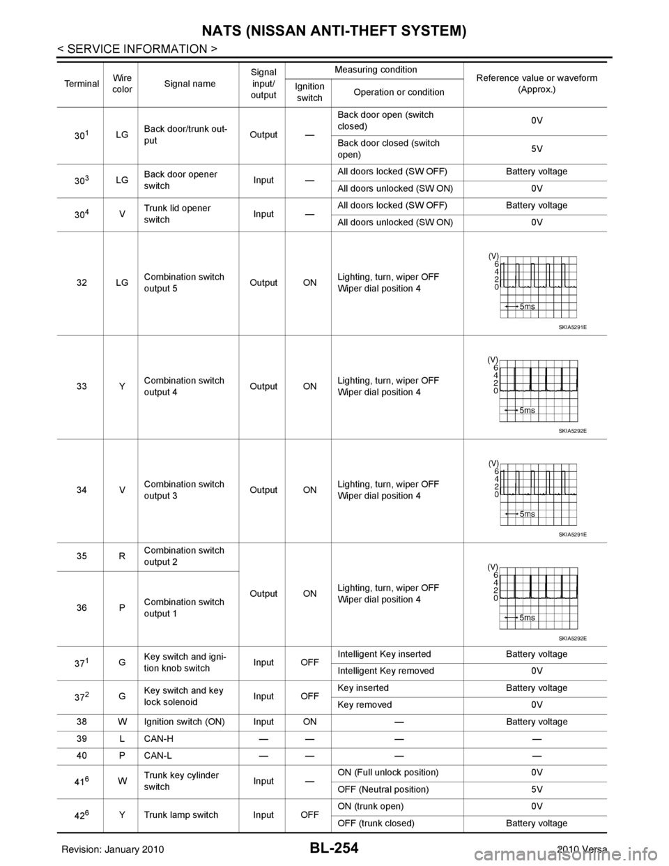
BL-254
< SERVICE INFORMATION >
NATS (NISSAN ANTI-THEFT SYSTEM)
301LGBack door/trunk out-
put Output —Back door open (switch
closed)
0V
Back door closed (switch
open) 5V
30
3LG Back door opener
switch
Input —All doors locked (SW OFF)
Battery voltage
All doors unlocked (SW ON) 0V
30
4V Trunk lid opener
switch
Input —All doors locked (SW OFF)
Battery voltage
All doors unlocked (SW ON) 0V
32 LG Combination switch
output 5 Output ONLighting, turn, wiper OFF
Wiper dial position 4
33 Y Combination switch
output 4 Output ON
Lighting, turn, wiper OFF
Wiper dial position 4
34 V Combination switch
output 3
Output ONLighting, turn, wiper OFF
Wiper dial position 4
35 R Combination switch
output 2
Output ONLighting, turn, wiper OFF
Wiper dial position 4
36 P Combination switch
output 1
37
1G Key switch and igni-
tion knob switch Input OFFIntelligent Key inserted
Battery voltage
Intelligent Key removed 0V
37
2G Key switch and key
lock solenoid Input OFFKey inserted
Battery voltage
Key removed 0V
38 W Ignition switch (ON) Input ON —Battery voltage
39 L CAN-H — —— —
40 P CAN-L — —— —
41
6W Trunk key cylinder
switch
Input —ON (Full unlock position)
0V
OFF (Neutral position) 5V
42
6Y Trunk lamp switch Input OFF ON (trunk open)
0V
OFF (trunk closed) Battery voltage
Te r m i n a l
Wire
color Signal name Signal
input/
output Measuring condition
Reference value or waveform
(Approx.)
Ignition
switch Operation or condition
SKIA5291E
SKIA5292E
SKIA5291E
SKIA5292E
Revision: January 20102010 Versa
Page 769 of 3745
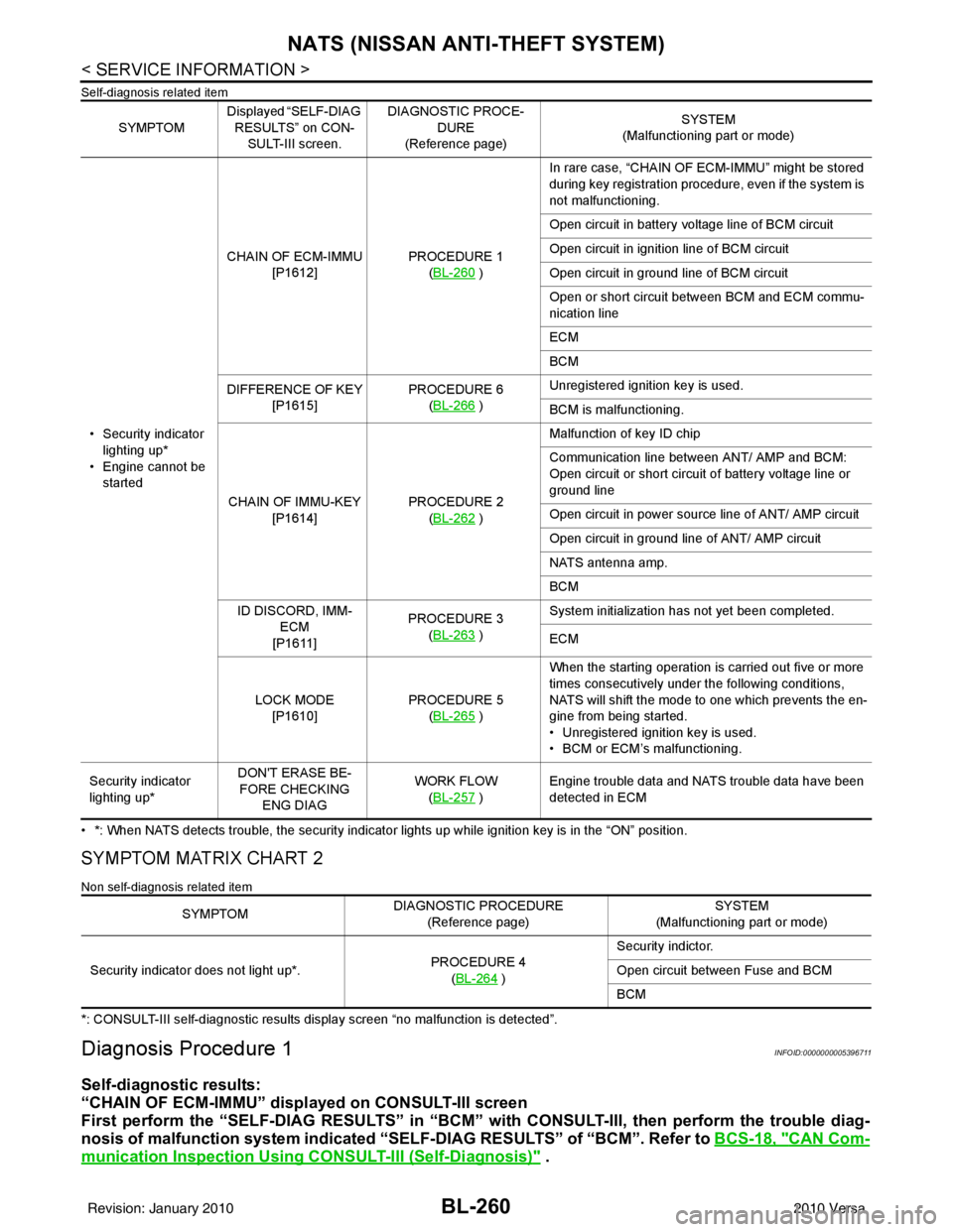
BL-260
< SERVICE INFORMATION >
NATS (NISSAN ANTI-THEFT SYSTEM)
Self-diagnosis related item
• *: When NATS detects trouble, the security indicator lights up while ignition key is in the “ON” position.
SYMPTOM MATRIX CHART 2
Non self-diagnosis related item
*: CONSULT-III self-diagnostic results display screen “no malfunction is detected”.
Diagnosis Procedure 1INFOID:0000000005396711
Self-diagnostic results:
“CHAIN OF ECM-IMMU” displayed on CONSULT-III screen
First perform the “SELF-DIAG RESU LTS” in “BCM” with CONSULT-III, then perform the trouble diag-
nosis of malfunction system indicated “SELF-DIAG RESULTS” of “BCM”. Refer to BCS-18, "
CAN Com-
munication Inspection Using CONSULT-III (Self-Diagnosis)" .
SYMPTOMDisplayed “SELF-DIAG
RESULTS” on CON- SULT-III screen. DIAGNOSTIC PROCE-
DURE
(Reference page) SYSTEM
(Malfunctioning part or mode)
• Security indicator lighting up*
• Engine cannot be started CHAIN OF ECM-IMMU
[P1612] PROCEDURE 1
(BL-260
) In rare case, “CHAIN OF ECM-IMMU” might be stored
during key registration procedure, even if the system is
not malfunctioning.
Open circuit in battery voltage line of BCM circuit
Open circuit in ignition line of BCM circuit
Open circuit in ground line of BCM circuit
Open or short circuit between BCM and ECM commu-
nication line
ECM
BCM
DIFFERENCE OF KEY [P1615] PROCEDURE 6
(BL-266
) Unregistered ignition key is used.
BCM is malfunctioning.
CHAIN OF IMMU-KEY [P1614] PROCEDURE 2
(BL-262
) Malfunction of key ID chip
Communication line between ANT/ AMP and BCM:
Open circuit or short circuit of battery voltage line or
ground line
Open circuit in power source line of ANT/ AMP circuit
Open circuit in ground line of ANT/ AMP circuit
NATS antenna amp.
BCM
ID DISCORD, IMM- ECM
[P1611] PROCEDURE 3
(BL-263
) System initialization has not yet been completed.
ECM
LOCK MODE [P1610] PROCEDURE 5
(BL-265
) When the starting operation is carried out five or more
times consecutively under the following conditions,
NATS will shift the mode to one which prevents the en-
gine from being started.
• Unregistered ignition key is used.
• BCM or ECM’s malfunctioning.
Security indicator
lighting up* DON'T ERASE BE-
FORE CHECKING ENG DIAG WORK FLOW
(BL-257
) Engine trouble data and NATS trouble data have been
detected in ECM
SYMPTOM
DIAGNOSTIC PROCEDURE
(Reference page) SYSTEM
(Malfunctioning part or mode)
Security indicator does not light up*. PROCEDURE 4
(BL-264
) Security indictor.
Open circuit between Fuse and BCM
BCM
Revision: January 20102010 Versa
Page 1211 of 3745

DI-1
ELECTRICAL
C
DE
F
G H
I
J
L
M
SECTION DI
A
B
DI
N
O P
CONTENTS
DRIVER INFORMATION SYSTEM
SERVICE INFORMATION .. ..........................2
PRECAUTION ................................................ .....2
Precaution for Supplemental Restraint System
(SRS) "AIR BAG" and "SEAT BELT PRE-TEN-
SIONER" ............................................................. ......
2
Precaution Necessary for Steering Wheel Rota-
tion After Battery Disconnect ............................... ......
2
COMBINATION METERS ...................................4
Component Parts and Harness Connector Loca-
tion ...................................................................... ......
4
System Description ...................................................4
Arrangement of Combination Meter ..........................6
Internal Circuit ...........................................................7
Wiring Diagram - METER - .......................................8
Combination Meter Harness Connector Terminal
Layout .....................................................................
10
Terminal and Reference Value for Combination
Meter .......................................................................
10
Self-Diagnosis Mode of Combination Meter ........ ....11
CONSULT-III Function (METER/M&A) ............... ....13
Trouble Diagnosis ...................................................14
Symptom Chart .......................................................15
Power Supply and Ground Circuit Inspection .........15
Vehicle Speed Signal Inspection .............................16
Engine Speed Signal Inspection .............................17
Fuel Level Sensor Signal Inspection .......................17
Fuel Gauge Fluctuates, Indicates Wrong Value, or
Varies ......................................................................
19
Fuel Gauge Does Not Move to Full-position ...........19
DTC [U1000] CAN Communication Circuit ......... ....19
Electrical Component Inspection .............................20
Removal and Installation .........................................20
WARNING LAMPS ......................................... ....21
Schematic ........................................................... ....21
Wiring Diagram - WARN - ................................... ....22
Oil Pressure Warning Lamp Stays Off (Ignition
Switch ON) .......................................................... ....
30
Oil Pressure Warning Lamp Does Not Turn Off
(Oil Pressure Is Normal) ...................................... ....
32
Component Inspection .............................................32
A/T INDICATOR ................................................34
System Description ..................................................34
Wiring Diagram - AT/IND - .......................................35
A/T Indicator Does Not Illuminate ............................36
CVT INDICATOR ...............................................38
System Description ..................................................38
Schematic ................................................................38
Wiring Diagram - CVTIND - .....................................39
CVT Indicator Does Not Illuminate ..........................41
WARNING CHIME .............................................43
Component Parts and Harness Connector Loca-
tion ....................................................................... ....
43
System Description ..................................................43
Wiring Diagram - CHIME - .......................................46
Terminal and Reference Value for BCM ..................47
CONSULT-III Function (B CM) .................................47
Trouble Diagnosis ................................................ ....48
Combination Meter Buzzer Circuit Inspection .........49
Front Door Switch LH Signal Inspection .............. ....50
Key Switch Signal Inspection (Without Intelligent
Key) ..................................................................... ....
51
Key Switch and Ignition Knob Switch Signal In-
spection (With Intelligent Key, When Mechanical
Key Is Used) ........................................................ ....
52
Lighting Switch Signal Inspection ............................54
Parking Brake Switch Signal Inspection ..................54
Electrical Component Inspection .............................55
Revision: January 20102010 Versa
Page 1253 of 3745
WARNING CHIMEDI-43
< SERVICE INFORMATION >
C
DE
F
G H
I
J
L
M A
B
DI
N
O P
WARNING CHIME
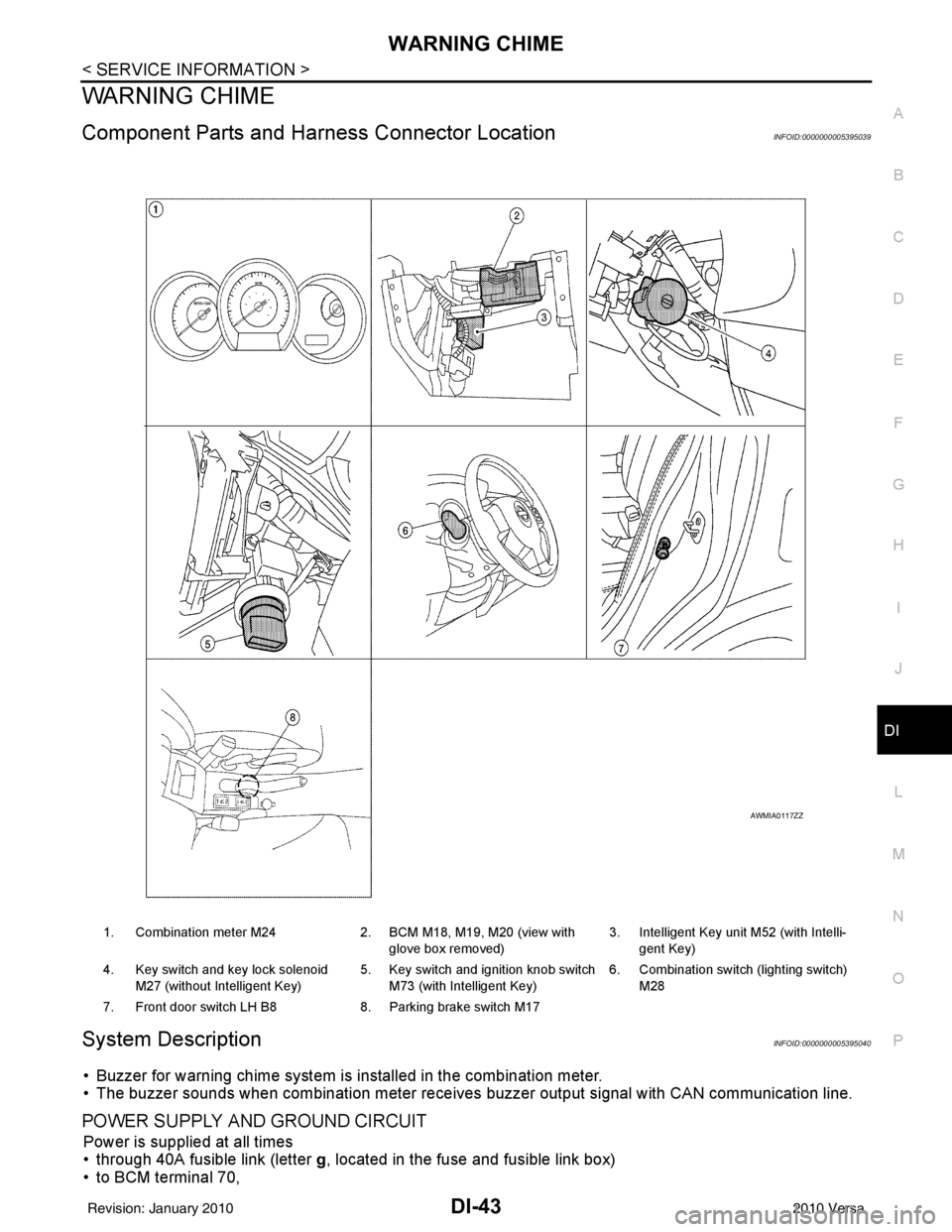
Component Parts and Har ness Connector LocationINFOID:0000000005395039
System DescriptionINFOID:0000000005395040
• Buzzer for warning chime system is installed in the combination meter.
• The buzzer sounds when combination meter receives buzzer output signal with CAN communication line.
POWER SUPPLY AND GROUND CIRCUIT
Power is supplied at all times
• through 40A fusible link (letter g, located in the fuse and fusible link box)
• to BCM terminal 70,
1. Combination meter M24 2. BCM M18, M19, M20 (view with
glove box removed) 3. Intelligent Key unit M52 (with Intelli-
gent Key)
4. Key switch and key lock solenoid M27 (without Intelligent Key) 5. Key switch and ignition knob switch
M73 (with Intelligent Key) 6. Combination switch (lighting switch)
M28
7. Front door switch LH B8 8. Parking brake switch M17
AWMIA0117ZZ
Revision: January 20102010 Versa
Page 1254 of 3745
![NISSAN LATIO 2010 Service Owners Manual DI-44
< SERVICE INFORMATION >
WARNING CHIME
• through 10A fuse [No. 8, located in the fuse block (J/B)]
• to BCM terminal 57,
• through 10A fuse [No. 13, located in the fuse block (J/B)]
• to](/img/5/57358/w960_57358-1253.png "NISSAN LATIO 2010 Service Owners Manual DI-44
< SERVICE INFORMATION >
WARNING CHIME
• through 10A fuse [No. 8, located in the fuse block (J/B)]
• to BCM terminal 57,
• through 10A fuse [No. 13, located in the fuse block (J/B)]
• to")
DI-44
< SERVICE INFORMATION >
WARNING CHIME
• through 10A fuse [No. 8, located in the fuse block (J/B)]
• to BCM terminal 57,
• through 10A fuse [No. 13, located in the fuse block (J/B)]
• to combination meter terminal 27.
With ignition switch in the ON or START position, power is supplied
• through 10A fuse [No. 6, located in the fuse block (J/B)]
• to BCM terminal 38,
• through 10A fuse [No. 3, located in the fuse block (J/B)]
• to combination meter terminal 28.
Ground is supplied
• to BCM terminal 67 and
• to combination meter terminals 21, 22 and 23
• through grounds M57 and M61.
IGNITION KEY WARNING CHIME (WITHOUT INTELLIGENT KEY)
With the key inserted into the key switch, and the ignition switch in the OFF or ACC position, when driver's
door is opened, the warning chime will sound.
• BCM detects key inserted into the ignition switch, and sends key warning signal to combination meter with CAN communication line.
• When combination meter receives key warning signal, it sounds warning chime.
IGNITION KEY WARNING CHIME (WITH INTELLIGENT KEY)
When Mechanical Key Is Used
With the key inserted into the key switch, and the igniti on switch in the LOCK or ACC position, when driver's
door is opened, the warning chime will sound.
• BCM detects key inserted into the ignition switch, and sends key warning signal to combination meter with
CAN communication line.
• When combination meter receives key warning signal, it sounds warning chime.
When Intelligent Key Is Carried With The Driver
Refer to BL-88, "System Description".
LIGHT WARNING CHIME
The warning chime sounds, when driver's door is opened (door switch ON) with lighting switch ON and the
ignition switch is in any position other than ON or START.
NOTE:
BCM detected lighting switch in the 1st or 2nd position, refer to LT-65, "
Combination Switch Reading Func-
tion".
• BCM detects headlamps are illuminated, and sends light warning signal to combination meter with CAN
communication lines.
WKIA5463E
WKIA5464E
Revision: January 20102010 Versa
Page 1258 of 3745
![NISSAN LATIO 2010 Service Owners Manual DI-48
< SERVICE INFORMATION >
WARNING CHIME
DATA MONITOR
Display Item List
ACTIVE TEST
Display Item List
SELF-DIAG RESULTS
Display Item List
NOTE:
If “CAN communication [U1000]” is indicated, afte](/img/5/57358/w960_57358-1257.png "NISSAN LATIO 2010 Service Owners Manual DI-48
< SERVICE INFORMATION >
WARNING CHIME
DATA MONITOR
Display Item List
ACTIVE TEST
Display Item List
SELF-DIAG RESULTS
Display Item List
NOTE:
If “CAN communication [U1000]” is indicated, afte")
DI-48
< SERVICE INFORMATION >
WARNING CHIME
DATA MONITOR
Display Item List
ACTIVE TEST
Display Item List
SELF-DIAG RESULTS
Display Item List
NOTE:
If “CAN communication [U1000]” is indicated, after printing the monitor item, go to “LAN system”. Refer to
LAN-17, "
Trouble Diagnosis Flow Chart".
Trouble DiagnosisINFOID:0000000005395044
HOW TO PERFORM TROUBLE DIAGNOSIS
1. Confirm the symptom and customer complaint.
2. Understand the outline of system. Refer to DI-43, "
System Description".
3. Perform the preliminary inspection. Refer to "PRELIMINARY INSPECTION".
4. According to symptom chart, repair or replac e the cause of the malfunction. Refer to "SYMPTOM
CHART".
5. Does warning chime system operate normally? If it operates normally, GO TO 6. If not, GO TO 4.
6. Inspection End.
PRELIMINARY INSPECTION
BCM diagnostic test item Diagnostic mode
Description
Inspection by part WORK SUPPORT
Supports inspections and adjustments. Commands are transmitted to the BCM for
setting the status suitable for required operation, input/output signals are received
from the BCM and received data is displayed.
DATA MONITOR Displays BCM input/output data in real time. ACTIVE TEST Operation of electrical loads can be checked by sending drive signal to them.
SELF-DIAG RESULTS Displays BCM self-diagnosis results.
CAN DIAG SUPPORT MNTR The result of transmit/receive diagnosis of CAN communication can be read. ECU PART NUMBER BCM part number can be read.CONFIGURATION Performs BCM configuration read/write functions.
Monitored item ALL SIGNALS SELECTION
FROM MENU Contents
IGN ON SW XX Indicates [ON/OFF] condition of ignition switch.
KEY ON SW XX Indicates [ON/OFF] condition of key switch.
DOOR SW-DR XX Indicates [ON/OFF] condition of front door switch LH.
LIGHT SW 1ST XX Indicates [ON/OFF] condition of lighting switch.
BUCKLE SW XX Indicates [ON/OFF] condition of seat belt buckle switch LH.
Test item Malfunction is detected when···
IGN KEY WARN ALM This test is able to check key warning chime operation.
LIGHT WARN ALM This test is able to check light warning chime operation.
SEAT BELT WARN TEST This test is able to check seat belt warning chime operation.
Display item [Code] Malfunction is detected when...
CAN communication [U1000] Malfunction is detected in CAN communication.
Revision: January 20102010 Versa