Lighting NISSAN LATIO 2010 Service Owner's Guide
[x] Cancel search | Manufacturer: NISSAN, Model Year: 2010, Model line: LATIO, Model: NISSAN LATIO 2010Pages: 3745, PDF Size: 73.67 MB
Page 1259 of 3745
WARNING CHIMEDI-49
< SERVICE INFORMATION >
C
DE
F
G H
I
J
L
M A
B
DI
N
O P
1.CHECK BCM
Perform self-diagnosis of BCM. Refer to DI-47, "
CONSULT-III Function (BCM)".
Self
-diagnostic results content
No malfunction detected>> GO TO 2.
Malfunction detected>> Check applicable parts, and repair or replace corresponding parts.
2.CHECK COMBINATION METER
Perform self-diagnosis of combination meter. Refer to DI-13, "
CONSULT-III Function (METER/M&A)".
Self
-diagnostic results content
No malfunction detected>> Inspection End.
Malfunction detected>> Check applicable parts, and repair or replace corresponding parts.
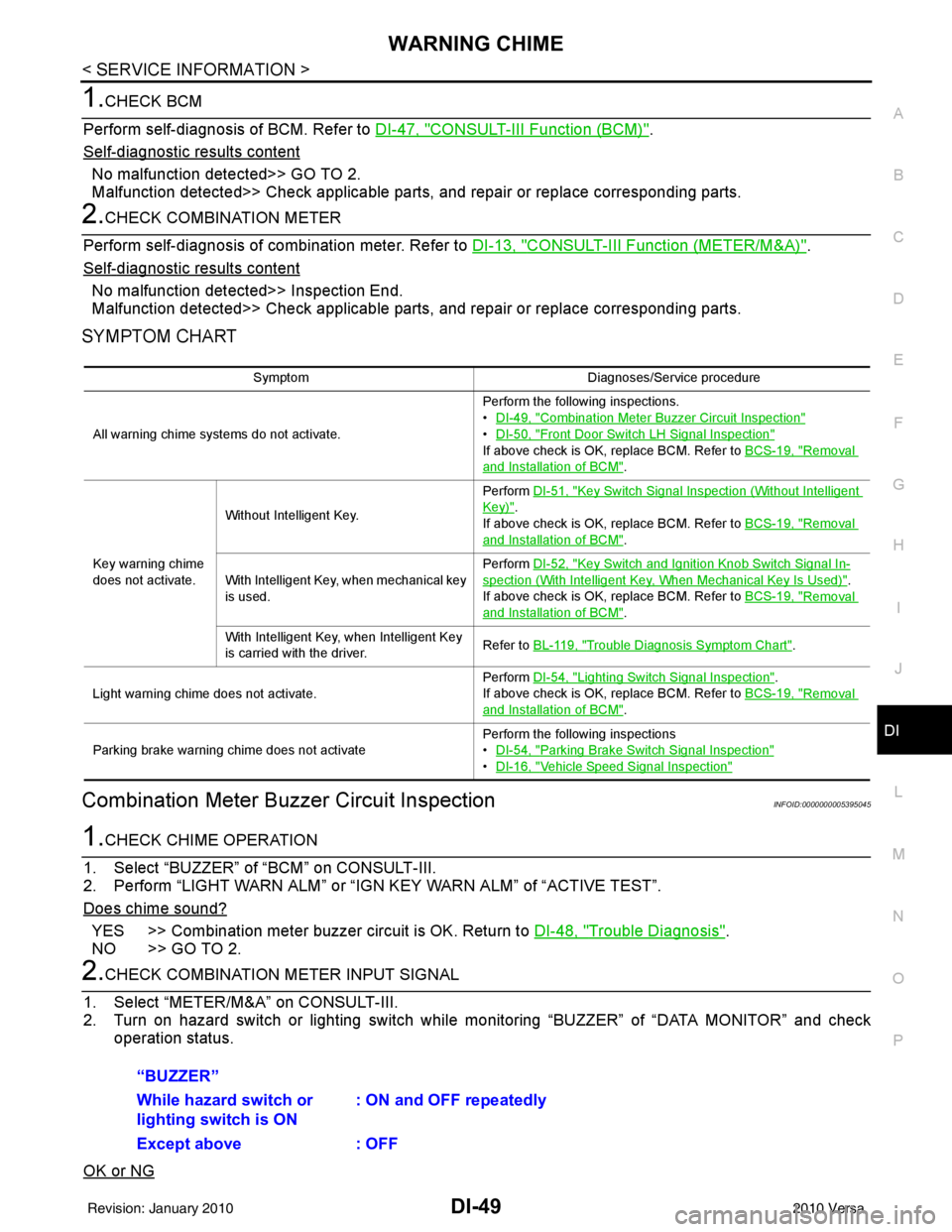
SYMPTOM CHART
Combination Meter Buzzer Circuit InspectionINFOID:0000000005395045
1.CHECK CHIME OPERATION
1. Select “BUZZER” of “BCM” on CONSULT-III.
2. Perform “LIGHT WARN ALM” or “IGN KEY WARN ALM” of “ACTIVE TEST”.
Does chime sound?
YES >> Combination meter buzzer circuit is OK. Return to DI-48, "Trouble Diagnosis".
NO >> GO TO 2.
2.CHECK COMBINATION METER INPUT SIGNAL
1. Select “METER/M&A” on CONSULT-III.
2. Turn on hazard switch or lighting switch while monitoring “BUZZER” of “DATA MONITOR” and check
operation status.
OK or NG
Symptom Diagnoses/Service procedure
All warning chime systems do not activate. Perform the following inspections.
•
DI-49, "
Combination Meter Buzzer Circuit Inspection"
•DI-50, "Front Door Switch LH Signal Inspection"
If above check is OK, replace BCM. Refer to BCS-19, "Removal
and Installation of BCM".
Key warning chime
does not activate. Without Intelligent Key.
Perform
DI-51, "
Key Switch Signal Inspection (Without Intelligent
Key)".
If above check is OK, replace BCM. Refer to BCS-19, "
Removal
and Installation of BCM".
With Intelligent Key, when mechanical key
is used. Perform
DI-52, "
Key Switch and Ignition Knob Switch Signal In-
spection (With Intelligent Key, When Mechanical Key Is Used)".
If above check is OK, replace BCM. Refer to BCS-19, "
Removal
and Installation of BCM".
With Intelligent Key, when Intelligent Key
is carried with the driver. Refer to BL-119, "
Trouble Diagnosis Symptom Chart".
Light warning chime does not activate. Perform
DI-54, "
Lighting Switch Signal Inspection".
If above check is OK, replace BCM. Refer to BCS-19, "
Removal
and Installation of BCM".
Parking brake warning chime does not activate Perform the following inspections
•
DI-54, "
Parking Brake Switch Signal Inspection"
•DI-16, "Vehicle Speed Signal Inspection"
“BUZZER”
While hazard switch or
lighting switch is ON : ON and OFF repeatedly
Except above : OFF
Revision: January 20102010 Versa
Page 1264 of 3745
DI-54
< SERVICE INFORMATION >
WARNING CHIME
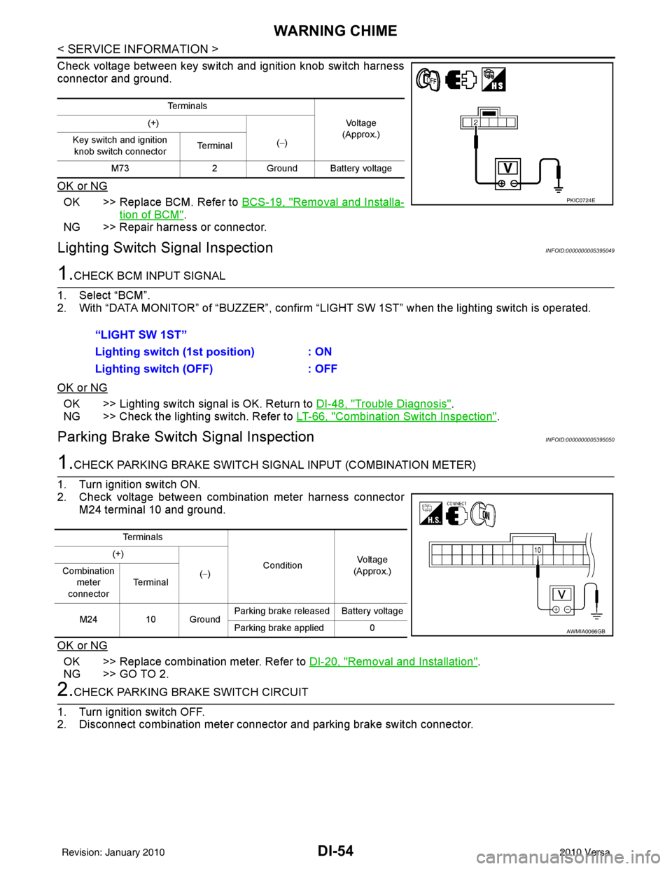
Check voltage between key switch and ignition knob switch harness
connector and ground.
OK or NG
OK >> Replace BCM. Refer to BCS-19, "Removal and Installa-
tion of BCM".
NG >> Repair harness or connector.
Lighting Switch Signal InspectionINFOID:0000000005395049
1.CHECK BCM INPUT SIGNAL
1. Select “BCM”.
2. With “DATA MONITOR” of “BUZZER”, confirm “LIG HT SW 1ST” when the lighting switch is operated.
OK or NG
OK >> Lighting switch signal is OK. Return to DI-48, "Trouble Diagnosis".
NG >> Check the lighting switch. Refer to LT-66, "
Combination Switch Inspection".
Parking Brake Switch Signal InspectionINFOID:0000000005395050
1.CHECK PARKING BRAKE SWITCH SIGNAL INPUT (COMBINATION METER)
1. Turn ignition switch ON.
2. Check voltage between combination meter harness connector M24 terminal 10 and ground.
OK or NG
OK >> Replace combination meter. Refer to DI-20, "Removal and Installation".
NG >> GO TO 2.
2.CHECK PARKING BRAKE SWITCH CIRCUIT
1. Turn ignition switch OFF.
2. Disconnect combination meter connector and parking brake switch connector.
Te r m i n a l s
Vo l ta g e
(Approx.)
(+)
(−)
Key switch and ignition
knob switch connector Te r m i n a l
M73 2Ground Battery voltage
PKIC0724E
“LIGHT SW 1ST”
Lighting switch ( 1st position) : ON
Lighting switch (OFF) : OFF
Te r m i n a l s
ConditionVoltag e
(Approx.)
(+)
(−)
Combination
meter
connector Te r m i n a l
M24 10 Ground Parking brake released Battery voltage
Parking brake applied 0
AWMIA0066GB
Revision: January 20102010 Versa
Page 1349 of 3745
![NISSAN LATIO 2010 Service Owners Guide EC-84
< FUNCTION DIAGNOSIS >[HR16DE]
ON BOARD DIAGNOSTIC (OBD) SYSTEM
ON BOARD DIAGNOST
IC (OBD) SYSTEM
Diagnosis DescriptionINFOID:0000000005398277
INTRODUCTION
The ECM has an on board diagnostic sys](/img/5/57358/w960_57358-1348.png "NISSAN LATIO 2010 Service Owners Guide EC-84
< FUNCTION DIAGNOSIS >[HR16DE]
ON BOARD DIAGNOSTIC (OBD) SYSTEM
ON BOARD DIAGNOST
IC (OBD) SYSTEM
Diagnosis DescriptionINFOID:0000000005398277
INTRODUCTION
The ECM has an on board diagnostic sys")
EC-84
< FUNCTION DIAGNOSIS >[HR16DE]
ON BOARD DIAGNOSTIC (OBD) SYSTEM
ON BOARD DIAGNOST
IC (OBD) SYSTEM
Diagnosis DescriptionINFOID:0000000005398277
INTRODUCTION
The ECM has an on board diagnostic system, which detects malfunctions related to engine sensors or actua-
tors. The ECM also records various emission-related diagnostic information including:
*: Service $0A is not applied for regions where it is not mandated.
The above information can be checked using procedures listed in the table below.
×: Applicable —: Not applicable
*: When DTC and 1st trip DTC simultaneously appear on the display, they cannot be clearly distinguished from each other.
The malfunction indicator lamp (MIL) on the instrument panel lights up when the same malfunction is detected
in two consecutive trips (Two trip detection logic), or when the ECM enters fail-safe mode. (Refer to EC-465,
"FailSafe".)
TWO TRIP DETECTION LOGIC
When a malfunction is detected for the first time, 1st trip DTC and 1st trip Freeze Frame data are stored in the
ECM memory. The MIL will not light up at this stage. <1st trip>
If the same malfunction is detected again during the next drive, the DTC and Freeze Frame data are stored in
the ECM memory, and the MIL lights up. The MIL lights up at the same time when the DTC is stored. <2nd
trip> The “trip” in the “Two Trip Detection Logic” means a driving mode in which self-diagnosis is performed
during vehicle operation. Specific on board diagnostic item s will cause the ECM to light up or blink the MIL,
and store DTC and Freeze Frame data, even in the 1st trip, as shown below.
× : Applicable —: Not applicable
DTC AND FREEZE FRAME DATA
Emission-related diagnostic information Diagnostic service
Diagnostic Trouble Code (DTC) Service $03 of SAE J1979/ISO 15031-5
Freeze Frame data Service $02 of SAE J1979/ISO 15031-5
System Readiness Test (SRT) code Service $01 of SAE J1979/ISO 15031-5
1st Trip Diagnostic Trouble Code (1st Trip DTC) Service $07 of SAE J1979/ISO 15031-5
1st Trip Freeze Frame data —
Test values and Test limits Service $06 of SAE J1979/ISO 15031-5
Calibration ID Service $09 of SAE J1979/ISO 15031-5
Permanent Diagno stic Trouble Code (Permanent DTC) Service $0A* of SAE J1979/ISO 15031-5
DTC 1st trip DTC Freeze
Frame data 1st trip Freeze
Frame data SRT code SRT status Test value Permanent
DTC status
CONSULT-III ×× × × ×× —×
GST ×× × —××××
ECM ××*— — — ×——
Items MIL
DTC1st trip DTC
1st trip 2nd trip
1st trip
displaying 2nd trip
displaying 1st trip
displaying 2nd trip
displaying
Blinking Lighting
up Blinking Lighting
up
Misfire (Possible three way catalyst
damage) — DTC: P0300 - P0304 is
being detected ×
———— — ×—
Misfire (Possible three way catalyst
damage) — DTC: P0300 - P0304 is
being detected ——
×—— ×——
One trip detection diagnoses
(Refer to EC-468, "
DTCIndex".) —
×—— ×—— —
Except above — — —×— ×× —
Revision: January 20102010 Versa
Page 1355 of 3745
![NISSAN LATIO 2010 Service Owners Guide EC-90
< FUNCTION DIAGNOSIS >[HR16DE]
ON BOARD DIAGNOSTIC (OBD) SYSTEM
• When any SRT codes are not set, MIL will flash periodically for 10 seconds.
PERMANENT DIAGNOSTIC TROUBLE CODE (PERMANENT DTC)](/img/5/57358/w960_57358-1354.png "NISSAN LATIO 2010 Service Owners Guide EC-90
< FUNCTION DIAGNOSIS >[HR16DE]
ON BOARD DIAGNOSTIC (OBD) SYSTEM
• When any SRT codes are not set, MIL will flash periodically for 10 seconds.
PERMANENT DIAGNOSTIC TROUBLE CODE (PERMANENT DTC)")
EC-90
< FUNCTION DIAGNOSIS >[HR16DE]
ON BOARD DIAGNOSTIC (OBD) SYSTEM
• When any SRT codes are not set, MIL will flash periodically for 10 seconds.
PERMANENT DIAGNOSTIC TROUBLE CODE (PERMANENT DTC)
Permanent DTC is defined in SAE J1979/ISO 15031-5 Service $0A.
ECM stores a DTC issuing a command of turning on MIL as a permanent DTC and keeps storing the DTC as
a permanent DTC until ECM judges that
there is no presence of malfunction.
Permanent DTCs cannot be erased by using the Erase f unction of CONSULT-III or Generic Scan Tool (GST)
and by disconnecting the battery to shut off power to ECM. This prevents a vehicle from passing the state
emission inspection without repairing a malfunctioning part.
When not passing the state emission inspection due to more than one permanent DTC, permanent DTCs
should be erased, referring to this manual.
NOTE:
• The important items in state emission inspection are t hat MIL is not ON, SRT test items are set, and perma-
nent DTCs are not included.
• Permanent DTCs do not apply for regions that permanent DTCs are not regulated by law.
Permanent DTC Item
For permanent DTC items, MIL turns on. Refer to EC-468, "DTCIndex".
Permanent DTC Set Timing
The setting timing of permanent DTC is stored in EC M with the lighting of MIL when a DTC is confirmed.
Permanent DTC Service Procedure
PBIB2317E
Revision: January 20102010 Versa
Page 1366 of 3745
![NISSAN LATIO 2010 Service Owners Guide ON BOARD DIAGNOSTIC (OBD) SYSTEMEC-101
< FUNCTION DIAGNOSIS > [HR16DE]
C
D
E
F
G H
I
J
K L
M A
EC
NP
O
HO2S2 MNTR(B1)
RICH/
LEAN • Display of heated oxygen sensor 2 signal:
RICH: means the amount of](/img/5/57358/w960_57358-1365.png "NISSAN LATIO 2010 Service Owners Guide ON BOARD DIAGNOSTIC (OBD) SYSTEMEC-101
< FUNCTION DIAGNOSIS > [HR16DE]
C
D
E
F
G H
I
J
K L
M A
EC
NP
O
HO2S2 MNTR(B1)
RICH/
LEAN • Display of heated oxygen sensor 2 signal:
RICH: means the amount of")
ON BOARD DIAGNOSTIC (OBD) SYSTEMEC-101
< FUNCTION DIAGNOSIS > [HR16DE]
C
D
E
F
G H
I
J
K L
M A
EC
NP
O
HO2S2 MNTR(B1)
RICH/
LEAN • Display of heated oxygen sensor 2 signal:
RICH: means the amount of oxygen after three way
catalyst is relatively small.
LEAN: means the amount of oxygen after three way
catalyst is relatively large. • When the engine is stopped, a certain
value is indicated.
VHCL SPEED SE km/h or
mph • The vehicle speed computed from the vehicle speed
signal sent from combination meter is displayed.
BATTERY VOLT V • The power supply voltage of ECM is displayed.
ACCEL SEN 1 V• The accelerator pedal position sensor signal voltage is
displayed. • ACCEL SEN 2 signal is converted by
ECM internally. Thus, it differs from
ECM terminal voltage signal.
ACCEL SEN 2
TP SEN 1-B1
V• The throttle position sensor signal voltage is dis-
played. • TP SEN 2-B1 signal is converted by
ECM internally. Thus, it differs from
ECM terminal voltage signal.
TP SEN 2-B1
FUEL T/TMP SE
°C or °F • The fuel temperature (determined by the signal volt-
age of the fuel tank temperature sensor) is displayed.
INT/A TEMP SE °C or °F • The intake air temperature (determined by the signal
voltage of the intake air temperature sensor) is indicat-
ed.
EVAP SYS PRES V • The signal voltage of EVAP control system pressure
sensor is displayed.
FUEL LEVEL SE V • The signal voltage of the fuel level sensor is displayed.
START SIGNAL ON/OFF • Indicates start signal status [ON/OFF] computed by
the ECM according to the signals of engine speed and
battery voltage. • After starting the engine, [OFF] is dis-
played regardless of the starter sig-
nal.
CLSD THL POS ON/OFF • Indicates idle position [ON/OFF] computed by ECM
according to the accelerator pedal position sensor sig-
nal.
AIR COND SIG ON/OFF • Indicates [ON/OFF] condition of the air conditioner
switch determined by the air conditioner ON signal.
P/N POSI SW ON/OFF • Indicates [ON/OFF] condit
ion from the park/neutral
position (PNP) signal.
PW/ST SIGNAL ON/OFF • [ON/OFF] condition of the power steering system (de-
termined by the signal sent from EPS control unit) is
indicated.
LOAD SIGNAL ON/OFF • Indicates [ON/OFF] condition from the electrical load
signal.
ON: Rear window defogger switch is ON and/or light-
ing switch is in 2nd position.
OFF: Both rear window defogger switch and lighting
switch are OFF.
IGNITION SW ON/OFF • Indicates [ON/OFF] condition from ignition switch sig-
nal.
HEATER FAN SW ON/OFF • Indicates [ON/OFF] condition from the heater fan
switch signal.
BRAKE SW ON/OFF• Indicates [ON/OFF] condition from the stop lamp
switch signal.
INJ PULSE-B1 msec • Indicates the actual fuel injection pulse width compen-
sated by ECM according to the input signals. • When the engine is stopped, a certain
computed value is indicated.
IGN TIMING BTDC• Indicates the ignition timing computed by ECM ac-
cording to the input signals. • When the engine is stopped, a certain
value is indicated.
CAL/LD VALUE %• “Calculated load value” indicates the value of the cur-
rent air flow divided by peak air flow.
MASS AIRFLOW g·m/s • Indicates the mass air flow computed by ECM accord-
ing to the signal voltage of the mass air flow sensor.
Monitored item Unit
DescriptionRemarks
Revision: January 20102010 Versa
Page 1371 of 3745
![NISSAN LATIO 2010 Service Owners Guide EC-106
< COMPONENT DIAGNOSIS >[HR16DE]
TROUBLE DIAGNOSIS - SPECIFICATION VALUE
COMPONENT DIAGNOSIS
TROUBLE DIAGNOSIS - SPECIFICATION VALUE
DescriptionINFOID:0000000005398280
The specification (SP) val](/img/5/57358/w960_57358-1370.png "NISSAN LATIO 2010 Service Owners Guide EC-106
< COMPONENT DIAGNOSIS >[HR16DE]
TROUBLE DIAGNOSIS - SPECIFICATION VALUE
COMPONENT DIAGNOSIS
TROUBLE DIAGNOSIS - SPECIFICATION VALUE
DescriptionINFOID:0000000005398280
The specification (SP) val")
EC-106
< COMPONENT DIAGNOSIS >[HR16DE]
TROUBLE DIAGNOSIS - SPECIFICATION VALUE
COMPONENT DIAGNOSIS
TROUBLE DIAGNOSIS - SPECIFICATION VALUE
DescriptionINFOID:0000000005398280
The specification (SP) value indicates the tolerance of
the value that is displayed in “SPEC” of “DATA MONI-
TOR” mode of CONSULT-III during normal operation of the Engine Control System. When the value in “SPEC”
of “DATA MONITOR” mode is within the SP value, the Engine Control System is confirmed OK. When the
value in “SPEC” of “DATA MONITOR” mode is NOT withi n the SP value, the Engine Control System may have
one or more malfunctions.
The SP value is used to detect malfunctions that may af fect the Engine Control System, but will not light the
MIL.
The SP value will be displayed for the following three items:
• B/FUEL SCHDL (The fuel injection pulse width progr ammed into ECM prior to any learned on board correc-
tion)
• A/F ALPHA-B1 (The mean value of air-fuel ratio feedback correction factor per cycle)
• MAS A/F SE-B1 (The signal voltage of the mass air flow sensor)
Component Function CheckINFOID:0000000005398281
1.START
Make sure that all of the following conditions are satisfied.
• Vehicle driven distance: More than 5,000 km (3,107 miles)
• Barometric pressure: 98.3 - 104.3 kPa (1.003 - 1.064 kg/cm
2, 14.25 - 15.12 psi)
• Atmospheric temperature: 20 - 30 °C (68 - 86° F)
• Engine coolant temperature: 75 - 95 °C (167 - 203° F)
• Transmission: Warmed-up
- A/T models: After the engine is warmed up to norma l operating temperature, drive vehicle until “FLUID
TEMP SE” (A/T fluid te mperature sensor signal) indicates more than 60 °C (140 °F).
- M/T models: After the engine is warmed up to normal operating temperature, drive vehicle for 5 minutes.
• Electrical load: Not applied
- Rear window defogger switch, air conditioner switch, lighting switch are OFF. Steering wheel is straight
ahead.
• Engine speed: Idle
>> GO TO 2.
2.PERFORM “SPEC” OF “DATA MONITOR” MODE
With CONSULT-III
NOTE:
Perform “SPEC” in “DATA MONITOR” mode in maximum scale display.
1. Perform EC-20, "
BASIC INSPECTION : Special Repair Requirement".
2. Select “B/FUEL SCHDL”, “A/F ALPHA-B1” and “MAS A/F SE-B1” in “SPEC” of “DATA MONITOR” mode
with CONSULT-III.
3. Make sure that monitor items are within the SP value.
Is the inspection result normal?
YES >> END
NO >> Go to EC-107, "
Diagnosis Procedure".
Revision: January 20102010 Versa
Page 1686 of 3745
![NISSAN LATIO 2010 Service Owners Guide ELECTRICAL LOAD SIGNALEC-421
< COMPONENT DIAGNOSIS > [HR16DE]
C
D
E
F
G H
I
J
K L
M A
EC
NP
O
ELECTRICAL LOAD SIGNAL
DescriptionINFOID:0000000005398601
The electrical load signal (Headlamp switch sign](/img/5/57358/w960_57358-1685.png "NISSAN LATIO 2010 Service Owners Guide ELECTRICAL LOAD SIGNALEC-421
< COMPONENT DIAGNOSIS > [HR16DE]
C
D
E
F
G H
I
J
K L
M A
EC
NP
O
ELECTRICAL LOAD SIGNAL
DescriptionINFOID:0000000005398601
The electrical load signal (Headlamp switch sign")
ELECTRICAL LOAD SIGNALEC-421
< COMPONENT DIAGNOSIS > [HR16DE]
C
D
E
F
G H
I
J
K L
M A
EC
NP
O
ELECTRICAL LOAD SIGNAL
DescriptionINFOID:0000000005398601
The electrical load signal (Headlamp switch signal, rear
window defogger switch signal, etc.) is transferred via
the CAN communication line.
Component Function CheckINFOID:0000000005398602
1.CHECK REAR WINDOW DEF OGGER SWITCH FUNCTION
1. Turn ignition switch ON.
2. Connect CONSULT-III and select “DATA MONITOR” mode.
3. Select “LOAD SIGNAL” and check indication under the following conditions.
Is the inspection result normal?
YES >> GO TO 2.
NO >> Go to EC-421, "
Diagnosis Procedure".
2.CHECK LIGHTING SWITCH FUNCTION
Check “LOAD SIGNAL” indication under the following conditions.
Is the inspection result normal?
YES >> GO TO 3.
NO >> Go to EC-421, "
Diagnosis Procedure".
3.CHECK HEATER FAN CONTROL SWITCH FUNCTION
Select “HEATER FAN SW” and check indication under the following conditions.
Is the inspection result normal?
YES >> INSPECTION END
NO >> Go to EC-421, "
Diagnosis Procedure".
Diagnosis ProcedureINFOID:0000000005398603
1.INSPECTION START
Confirm the malfunctioning circuit (rear window defogger, headlamp or heater fan). Refer to EC-421, "
Compo-
nent Function Check".
Which circuit is related to the incident?
Rear window defogger>>GO TO 2.
Headlamp>>GO TO 3.
Heater fan>>GO TO 4.
2.CHECK REAR WINDOW DEFOGGER SYSTEM
Refer to GW-55, "
Work Flow".
Monitor item ConditionIndication
LOAD SIGNAL Rear window defogger switch ON ON
OFF OFF
Monitor item
ConditionIndication
LOAD SIGNAL Lighting switch ON at 2nd position ON
OFF
OFF
Monitor item ConditionIndication
HEATER FAN SW Heater fan control switch ON ON
OFF OFF
Revision: January 20102010 Versa
Page 1720 of 3745
![NISSAN LATIO 2010 Service Owners Guide ECM
EC-455
< ECU DIAGNOSIS > [HR16DE]
C
D
E
F
G H
I
J
K L
M A
EC
NP
O
PW/ST SIGNAL
• Engine: After warming up, idle the
engine Steering wheel: Not being turned OFF
Steering wheel: Being turned
ON
L](/img/5/57358/w960_57358-1719.png "NISSAN LATIO 2010 Service Owners Guide ECM
EC-455
< ECU DIAGNOSIS > [HR16DE]
C
D
E
F
G H
I
J
K L
M A
EC
NP
O
PW/ST SIGNAL
• Engine: After warming up, idle the
engine Steering wheel: Not being turned OFF
Steering wheel: Being turned
ON
L")
ECM
EC-455
< ECU DIAGNOSIS > [HR16DE]
C
D
E
F
G H
I
J
K L
M A
EC
NP
O
PW/ST SIGNAL
• Engine: After warming up, idle the
engine Steering wheel: Not being turned OFF
Steering wheel: Being turned
ON
LOAD SIGNAL • Ignition switch: ON Rear window defogger switch: ON
and/or Lighting switch: 2nd position
ON
Rear window defogger switch and lighting
switch: OFF OFF
IGNITION SW • Ignition switch: ON → OFF → ON ON → OFF → ON
HEATER FAN SW • Engine: After warming up, idle the
engine Heater fan switch: ON
ON
Heater fan switch: OFF OFF
BRAKE SW • Ignition switch: ON Brake pedal: Fully released
OFF
Brake pedal: Slightly depressed ON
INJ PULSE-B1 • Engine: After warming up
• Selector lever position: P or N (A/
T) or Neutral (M/T)
• Air conditioner switch: OFF
•No load Idle
2.0 - 3.0 msec
2,000 rpm 1.9 - 2.9 msec
IGN TIMING • Engine: After warming up
• Selector lever position: P or N (A/
T) or Neutral (M/T)
• Air conditioner switch: OFF
•No load Idle
10 - 20°BTDC
2,000 rpm 25 - 45°BTDC
CAL/LD VALUE • Engine: After warming up
• Selector lever position: P or N (A/
T) or Neutral (M/T)
• Air conditioner switch: OFF
•No load Idle
10 - 35%
2,500 rpm 10 - 35%
MASS AIRFLOW • Engine: After warming up
• Selector lever position: P or N (A/
T) or Neutral (M/T)
• Air conditioner switch: OFF
•No load Idle
1.0 - 4.0 g·m/s
2,500 rpm 2.0 - 10.0 g·m/s
PURG VOL C/V • Engine: After warming up
• Selector lever position: P or N (A/
T) or Neutral (M/T)
• Air conditioner switch: OFF
•No load Idle
0%
2,000 rpm 0 - 50%
INT/V TIM (B1) • Engine: After warming up
• Selector lever position: P or N (A/
T) or Neutral (M/T)
• Air conditioner switch: OFF
•No load Idle
−5 - 5 °CA
2,000 rpm Approx. 0 - 40°CA
INT/V SOL (B1) • Engine: After warming up
• Selector lever position: P or N (A/
T) or Neutral (M/T)
• Air conditioner switch: OFF
•No load Idle
0 - 2%
2,000 rpm Approx. 0 - 90%
AIR COND RLY • Engine: After warming up, idle the
engine Air conditioner switch: OFF
OFF
Air conditioner switch: ON
(Compressor operates) ON
FUEL PUMP RLY • For 1 second after turning ignition switch: ON
• Engine running or cranking
ON
• E
xcept above OFF
THRTL RELAY • Ignition switch: ON ON
Monitor Item
Condition Values/Status
Revision: January 20102010 Versa
Page 1731 of 3745
![NISSAN LATIO 2010 Service Owners Guide EC-466
< ECU DIAGNOSIS >[HR16DE]
ECM
DTC RELATED ITEM
Detected itemsEngine operating condition in
fail-safe mode Remarks
Malfunction indicator
lamp circuit Engine speed will not rise
more than 2,50](/img/5/57358/w960_57358-1730.png "NISSAN LATIO 2010 Service Owners Guide EC-466
< ECU DIAGNOSIS >[HR16DE]
ECM
DTC RELATED ITEM
Detected itemsEngine operating condition in
fail-safe mode Remarks
Malfunction indicator
lamp circuit Engine speed will not rise
more than 2,50")
EC-466
< ECU DIAGNOSIS >[HR16DE]
ECM
DTC RELATED ITEM
Detected itemsEngine operating condition in
fail-safe mode Remarks
Malfunction indicator
lamp circuit Engine speed will not rise
more than 2,500 rpm due to
the fuel cut When there is an open circuit on MIL circuit, the ECM cannot warn the driver by
lighting up MIL when there is malfunction on engine control system.
Therefore, when electrical controlled throttle and part of ECM related diagnoses
are continuously detected as NG for 5 trips, ECM warns the driver that engine
control system malfunctions and MIL circuit is open by means of operating fail-
safe function.
The fail-safe function also operates when above diagnoses except MIL circuit
are detected and demands the driver to repair the malfunction.
DTC No. Detected items
Engine operating condition in fail-safe mode
P0011 Intake valve timing control The signal is not energized to the intake valve timing control solenoid valve and the valve control does not function.
P0102
P0103 Mass air flow sensor circuit Engine speed will not rise more than 2,400 rpm due to the fuel cut.
P0117
P0118 Engine coolant tempera-
ture sensor circuit Engine coolant temperature will be determined by ECM based on the following condition.
CONSULT-III displays the engine coolant temperature decided by ECM.
Condition Engine coolant temperature decided
(CONSULT-III display)
Just as ignition switch is turned ON
or START 40
°C (104 °F)
More than approx. 4 minutes after
engine starting 80
°C (176 °F)
Except as shown above 40 - 80
°C (104 - 176 °F)
(Depends on the time)
When the fail-safe system for engine coolant temperature sensor is activated, the cooling
fan operates while engine is running.
P0122
P0123
P0222
P0223
P2135 Throttle position sensor The ECM controls the electric throttle control actuator in regulating the throttle opening in
order for the idle position to be within +10 degrees.
The ECM regulates the opening speed of the throttle valve to be slower than the normal
condition.
So, the acceleration will be poor.
P0643 Sensor power supply ECM stops the electric throttle control actuator control, throttle valve is maintained at a fixed opening (approx. 5 degrees) by the return spring.
P0605 ECM (When ECM calculation function is malfunctioning:)
ECM stops the electric throttle control actuator control, throttle valve is maintained at a
fixed opening (approx. 5 degrees) by the return spring.
P1805 Brake switch ECM controls the electric throttle control actuator by regulating the throttle opening to a
small range.
Therefore, acceleration will be poor.
Vehicle condition Driving condition
When engine is idling Normal
When accelerating Poor acceleration
P2100
P2103 Throttle control motor relay ECM stops the electric throttle control actuator control, throttle valve is maintained at a
fixed opening (approx. 5 degrees) by the return spring.
P2101 Electric throttle control function ECM stops the electric throttle control actuator control, throttle valve is maintained at a
fixed opening (approx. 5 degrees) by the return spring.
P2118 Throttle control motor ECM stops the electric throttle control actuator control, throttle valve is maintained at a fixed opening (approx. 5 degrees) by the return spring.
Revision: January 20102010 Versa
Page 1806 of 3745
![NISSAN LATIO 2010 Service Owners Guide ON BOARD DIAGNOSTIC (OBD) SYSTEMEC-541
< SERVICE INFORMATION > [MR18DE]
C
D
E
F
G H
I
J
K L
M A
EC
NP
O
ON BOARD DIAGNOSTIC (OBD) SYSTEM
IntroductionINFOID:0000000005532399
The ECM has an on board dia](/img/5/57358/w960_57358-1805.png "NISSAN LATIO 2010 Service Owners Guide ON BOARD DIAGNOSTIC (OBD) SYSTEMEC-541
< SERVICE INFORMATION > [MR18DE]
C
D
E
F
G H
I
J
K L
M A
EC
NP
O
ON BOARD DIAGNOSTIC (OBD) SYSTEM
IntroductionINFOID:0000000005532399
The ECM has an on board dia")
ON BOARD DIAGNOSTIC (OBD) SYSTEMEC-541
< SERVICE INFORMATION > [MR18DE]
C
D
E
F
G H
I
J
K L
M A
EC
NP
O
ON BOARD DIAGNOSTIC (OBD) SYSTEM
IntroductionINFOID:0000000005532399
The ECM has an on board diagnostic system, which detects malfunctions related to engine sensors or actua-
tors. The ECM also records various emission-related diagnostic information including:
*: Service $0A is not applied for regions where it is not mandated.
The above information can be checked using procedures listed in the table below.
×
: Applicable —: Not applicable
*: When DTC and 1st trip DTC simultaneously appear on the display, they cannot be clearly distinguished from each other.
The malfunction indicator lamp (MIL) on the instrument panel lights up when the same malfunction is detected
in two consecutive trips (Two trip detection logic), or when the ECM enters fail-safe mode.
(Refer to EC-590, "
Fail-Safe Chart".)
Two Trip Detection LogicINFOID:0000000005532400
When a malfunction is detected for the first time, 1st tr ip DTC and 1st trip Freeze Frame data are stored in the
ECM memory. The MIL will not light up at this stage. <1st trip>
If the same malfunction is detected again during the next drive, the DTC and Freeze Frame data are stored in
the ECM memory, and the MIL lights up. The MIL lights up at the same time when the DTC is stored. <2nd
trip> The “trip” in the “Two Trip Detection Logic” m eans a driving mode in which self-diagnosis is performed
during vehicle operation. Specific on board diagnostic item s will cause the ECM to light up or blink the MIL,
and store DTC and Freeze Frame data, even in the 1st trip, as shown below.
× : Applicable —: Not applicable
Emission-related diagnostic information Diagnostic service
Diagnostic Trouble Code (DTC) Service $03 of SAE J1979 /ISO 15031-5
Freeze Frame data Service $02 of SAE J1979/ISO 15031-5
System Readiness Test (SRT) code Service $01 of SAE J1 979/ISO 15031-5
1st Trip Diagnostic Trouble Code (1st Trip DTC) Service $07 of SAE J1979/ISO 15031-5
1st Trip Freeze Frame data —
Test values and Test limits Service $06 of SAE J1979/ISO 15031-5
Calibration ID Service $09 of SAE J1979/ISO 15031-5
Permanent Diagnostic Trouble Code (Permanent DTC) Service $0A* of SAE J1979/ISO 15031-5
DTC 1st trip DTCFreeze
Frame data 1st trip Freeze
Frame data SRT code SRT status Test value Permanent
DTC status
CONSULT-III ×× × × ×× —×
GST ×× × —××××
ECM ××*— — — ×——
Items MIL
DTC1st trip DTC
1st trip 2nd trip
1st trip
displaying 2nd trip
displaying 1st trip
displaying 2nd trip
display-
ing
Blinking Lighting
up Blinking
Lighting
up
Misfire (Possible three way catalyst
damage) — DTC: P0300 - P0304 is
being detected ×
———— — ×—
Misfire (Possible three way catalyst
damage) — DTC: P0300 - P0304 is
being detected ——
×—— ×——
One trip detection diagnoses
(Refer to EC-542, "
Emission-relat-
ed Diagnostic Information".) —
×—— ×———
Except above — — —×— ×× —
Revision: January 20102010 Versa