NISSAN LATIO 2010 Service Repair Manual
Manufacturer: NISSAN, Model Year: 2010, Model line: LATIO, Model: NISSAN LATIO 2010Pages: 3745, PDF Size: 73.67 MB
Page 3721 of 3745
WW-16
< SERVICE INFORMATION >
FRONT WIPER AND WASHER SYSTEM
OK >> Replace front wiper motor. Refer to WW-21, "Removal and Installation of Front Wiper Drive
Assembly" .
NG >> Replace IPDM E/R. Refer to PG-28, "
Removal and Installation of IPDM E/R" .
Front Wiper Does Not Return to Stop Positi on (After Front Wiper Operates for 10 Sec-
onds, They Stop for 20 Second s, and After Repeating the Operation Five Times, They
Become Inoperative)
INFOID:0000000005395066
CAUTION:
• When auto-stop signal has not varied for 10 seconds or longer while IPDM E/R is operating front wip-
ers, IPDM E/R considers that front wipers are locked, and stops wiper output. That causes this symp-
tom.
• This status can be checked by “DATA MONITOR” of “IPDM E/R” on which “WIPER PROT” item
shows “BLOCK”.
1.CHECK FRONT WIPER STOP SIGNAL
With CONSULT-lIl
Select “IPDM E/R” on CONSULT-III. With “DATA MONITOR”, make sure that “WIP AUTO STOP” turns “ACT
P” - “STOP P” linked with wiper operation.
Without CONSULT-llI
GO TO 2.
OK or NG
OK >> Replace IPDM E/R. Refer to PG-28, "Removal and Installation of IPDM E/R" .
NG >> GO TO 2.
2.CHECK IPDM E/R
1. Turn ignition switch ON.
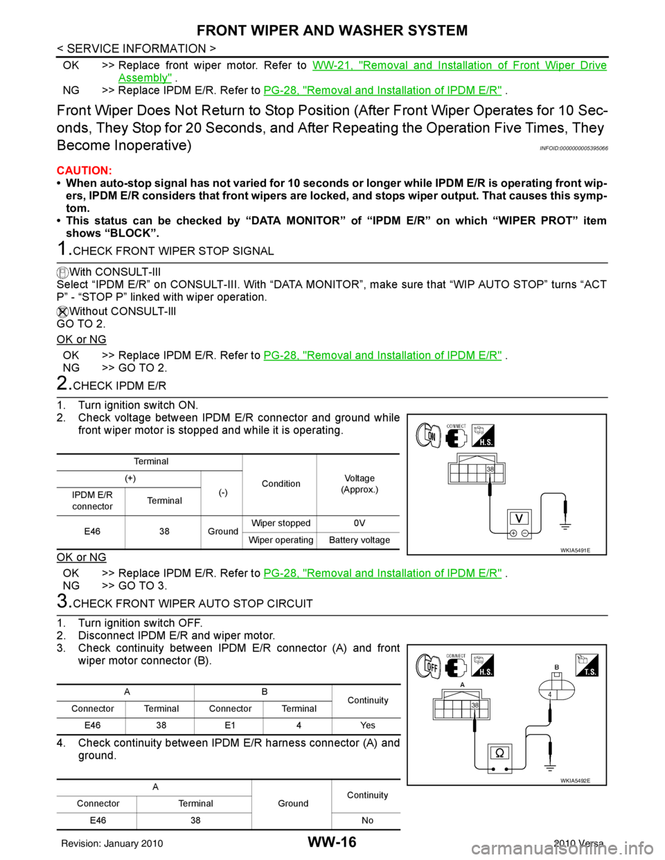
2. Check voltage between IPDM E/R connector and ground while front wiper motor is stopped and while it is operating.
OK or NG
OK >> Replace IPDM E/R. Refer to PG-28, "Removal and Installation of IPDM E/R" .
NG >> GO TO 3.
3.CHECK FRONT WIPER AUTO STOP CIRCUIT
1. Turn ignition switch OFF.
2. Disconnect IPDM E/R and wiper motor.
3. Check continuity between IPDM E/R connector (A) and front wiper motor connector (B).
4. Check continuity between IPDM E/R harness connector (A) and
ground.
Te r m i n a l
ConditionVo l ta g e
(Approx.)
(+)
(-)
IPDM E/R
connector Te r m i n a l
E46 38 Ground Wiper stopped 0V
Wiper operating Battery voltage
WKIA5491E
AB Continuity
Connector Terminal Connector Terminal
E46 38E1 4Yes
A GroundContinuity
Connector Terminal
E46 38 No
WKIA5492E
Revision: January 20102010 Versa
Page 3722 of 3745
FRONT WIPER AND WASHER SYSTEMWW-17
< SERVICE INFORMATION >
C
DE
F
G H
I
J
L
M A
B
WW
N
O P
OK or NG
OK >> Replace front wiper motor. Refer to WW-21, "Removal and Installation of Front Wiper Drive
Assembly" .
NG >> Repair or replace harness.
Only Front Wiper Low Does Not OperateINFOID:0000000005395067
1.ACTIVE TEST
With CONSULT-lIl
1. Select “IPDM E/R” on CONSUL T-III, and select “ACTIVE TEST” on “SELECT DIAG MODE” screen.
2. Select “FRONT WIPER” on “SELECT TEST ITEM” screen.
3. Touch “LO” screen.
Without CONSULT-lIl
Start auto active test. Refer to PG-20, "
Auto Active Test" .
Does front wiper operate normally?
YES >> Refer to LT-66, "Combination Switch Inspection" .
NO >> GO TO 2.
2.CHECK FRONT WIPER MOTOR CIRCUIT
1. Turn ignition switch OFF.
2. Disconnect IPDM E/R and front wiper motor.
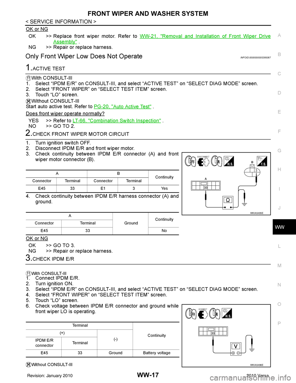
3. Check continuity between IPDM E/R connector (A) and front wiper motor connector (B).
4. Check continuity between IPDM E/R harness connector (A) and ground.
OK or NG
OK >> GO TO 3.
NG >> Repair or replace harness.
3.CHECK IPDM E/R
With CONSULT-lIl
1. Connect IPDM E/R.
2. Turn ignition ON.
3. Select “IPDM E/R” on CONSUL T-III, and select “ACTIVE TEST” on “SELECT DIAG MODE” screen.
4. Select “FRONT WIPER” on “SELECT TEST ITEM” screen.
5. Touch “LO” screen.
6. Check voltage between IPDM E/R connector and ground while front wiper LO is operating.
Without CONSULT-lIl
AB Continuity
Connector Terminal Connector Terminal
E45 33E1 3Yes
A GroundContinuity
Connector Terminal
E45 33 No
WKIA5495E
Te r m i n a l
Continuity
(+)
(-)
IPDM E/R
connector Te r m i n a l
E45 33Ground Battery voltage
WKIA5496E
Revision: January 20102010 Versa
Page 3723 of 3745
WW-18
< SERVICE INFORMATION >
FRONT WIPER AND WASHER SYSTEM
1. Connect IPDM E/R.
2. Turn ignition ON.
3. Start auto active test. Refer to PG-20, "
Auto Active Test" .
4. Check voltage between IPDM E/R connector and ground while front wiper LO is operating.
OK or NG
OK >> Replace front wiper motor. Refer to WW-21, "Removal and Installation of Front Wiper Drive
Assembly" .
NG >> Replace IPDM E/R. Refer to PG-28, "
Removal and Installation of IPDM E/R" .
Only Front Wiper High Does Not OperateINFOID:0000000005395068
1.ACTIVE TEST
With CONSULT-Ill
1. Select “IPDM E/R” on CONSULT-III, and sele ct “ACTIVE TEST” on “SELECT DIAG MODE” screen.
2. Select “FRONT WIPER” on “SELECT TEST ITEM” screen.
3. Touch “HI” screen.
Without CONSULT-lIl
Start auto active test. Refer to PG-20, "
Auto Active Test" .
Does front wiper operate normally?
YES >> Refer to LT-66, "Combination Switch Inspection" .
NO >> GO TO 2.
2.CHECK FRONT WIPER MOTOR CIRCUIT
1. Turn ignition switch OFF.
2. Disconnect IPDM E/R connector E45 and front wiper motor connector E1.
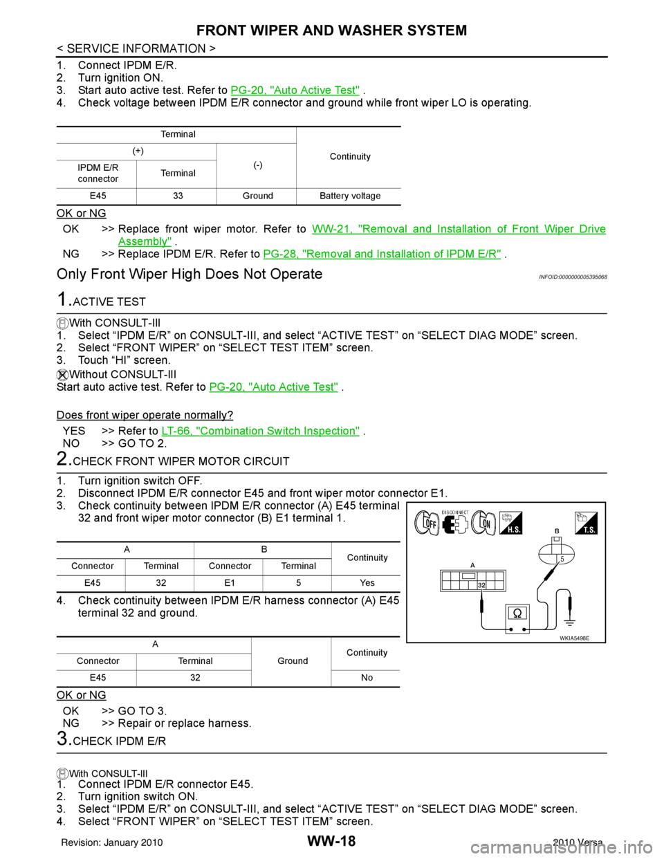
3. Check continuity between IPDM E/R connector (A) E45 terminal 32 and front wiper motor connector (B) E1 terminal 1.
4. Check continuity between IPDM E/R harness connector (A) E45 terminal 32 and ground.
OK or NG
OK >> GO TO 3.
NG >> Repair or replace harness.
3.CHECK IPDM E/R
With CONSULT-lIl
1. Connect IPDM E/R connector E45.
2. Turn ignition switch ON.
3. Select “IPDM E/R” on CONSULT-III, and sele ct “ACTIVE TEST” on “SELECT DIAG MODE” screen.
4. Select “FRONT WIPER” on “SELECT TEST ITEM” screen.
Te r m i n a l
Continuity
(+)
(-)
IPDM E/R
connector Te r m i n a l
E45 33Ground Battery voltage
AB
Continuity
Connector Terminal Connector Terminal
E45 32E1 5Yes
A GroundContinuity
Connector Terminal
E45 32 No
WKIA5498E
Revision: January 20102010 Versa
Page 3724 of 3745
FRONT WIPER AND WASHER SYSTEMWW-19
< SERVICE INFORMATION >
C
DE
F
G H
I
J
L
M A
B
WW
N
O P
5. Touch “HI” screen.
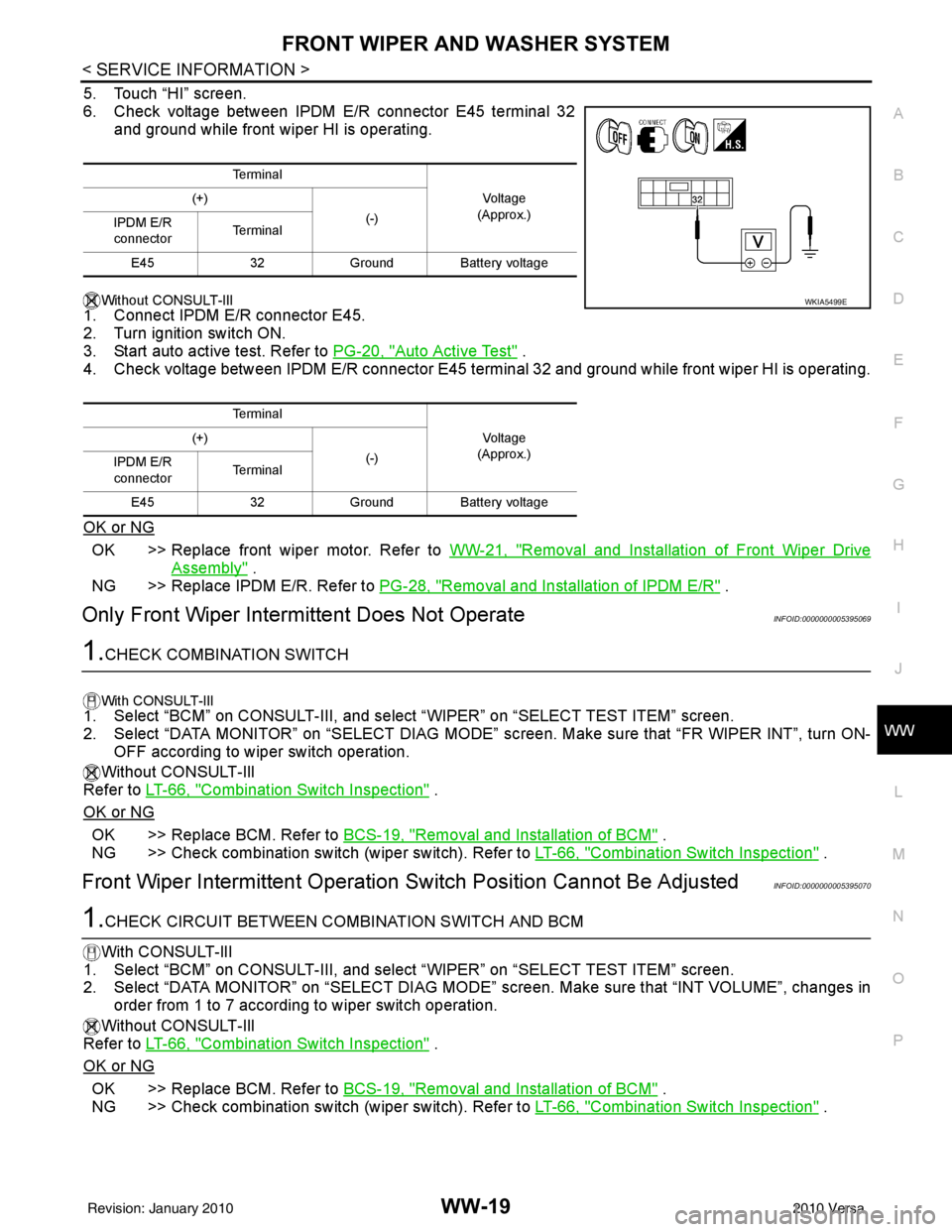
6. Check voltage between IPDM E/R connector E45 terminal 32 and ground while front wiper HI is operating.
Without CONSULT-lIl
1. Connect IPDM E/R connector E45.
2. Turn ignition switch ON.
3. Start auto active test. Refer to PG-20, "
Auto Active Test" .
4. Check voltage between IPDM E/R connector E45 terminal 32 and ground while front wiper HI is operating.
OK or NG
OK >> Replace front wiper motor. Refer to WW-21, "Removal and Installation of Front Wiper Drive
Assembly" .
NG >> Replace IPDM E/R. Refer to PG-28, "
Removal and Installation of IPDM E/R" .
Only Front Wiper Intermittent Does Not OperateINFOID:0000000005395069
1.CHECK COMBINATION SWITCH
With CONSULT-lIl1. Select “BCM” on CONSULT-III, and sele ct “WIPER” on “SELECT TEST ITEM” screen.
2. Select “DATA MONITOR” on “SELECT DIAG MODE” sc reen. Make sure that “FR WIPER INT”, turn ON-
OFF according to wiper switch operation.
Without CONSULT-Ill
Refer to LT-66, "
Combination Switch Inspection" .
OK or NG
OK >> Replace BCM. Refer to BCS-19, "Removal and Installation of BCM" .
NG >> Check combination switch (wiper switch). Refer to LT-66, "
Combination Switch Inspection" .
Front Wiper Intermittent Operation Switch Position Cannot Be AdjustedINFOID:0000000005395070
1.CHECK CIRCUIT BETWEEN COMB INATION SWITCH AND BCM
With CONSULT-lIl
1. Select “BCM” on CONSULT-III, and select “WIPER” on “SELECT TEST ITEM” screen.
2. Select “DATA MONITOR” on “SELECT DIAG MODE” screen. Make sure that “INT VOLUME”, changes in
order from 1 to 7 according to wiper switch operation.
Without CONSULT-Ill
Refer to LT-66, "
Combination Switch Inspection" .
OK or NG
OK >> Replace BCM. Refer to BCS-19, "Removal and Installation of BCM" .
NG >> Check combination switch (wiper switch). Refer to LT-66, "
Combination Switch Inspection" .
Te r m i n a l
Vo l ta g e
(Approx.)
(+)
(-)
IPDM E/R
connector Te r m i n a l
E45 32Ground Battery voltage
Te r m i n a l Vo l ta g e
(Approx.)
(+)
(-)
IPDM E/R
connector Te r m i n a l
E45 32Ground Battery voltage
WKIA5499E
Revision: January 20102010 Versa
Page 3725 of 3745
WW-20
< SERVICE INFORMATION >
FRONT WIPER AND WASHER SYSTEM
Wiper Does Not Wipe Wh en Front Washer Operates
INFOID:0000000005395071
1.CHECK CIRCUIT BETWEEN COMB INATION SWITCH AND BCM
With CONSULT-lIl
1. Select “BCM” on CONSULT-III, and sele ct “WIPER” on “SELECT TEST ITEM” screen.
2. Select “DATA MONITOR” on “SELECT DIAG MODE” screen. Make sure that “FR WASHER SW” turn ON-
OFF according to front wiper switch operation.
Without CONSULT-Ill
Refer to LT-66, "
Combination Switch Inspection" .
OK or NG
OK >> Replace BCM. Refer to BCS-19, "Removal and Installation of BCM" .
NG >> Check combination switch (wiper switch). Refer to LT-66, "
Combination Switch Inspection" .
Front Wiper Does Not StopINFOID:0000000005395072
1.CHECK CIRCUIT BETWEEN COMBINATION SWITCH AND BCM
With CONSULT-lIl
1. Select “BCM” on CONSULT-III, and sele ct “WIPER” on “SELECT TEST ITEM” screen.
2. Select “DATA MONITOR” on “SELECT DIAG MODE ” screen. Make sure that “FR WIPER INT”, “FR
WIPER LOW”, “FR WIPER HI”, and “FR WASHER SW” turn ON-OFF according to front wiper switch
operation.
Without CONSULT-Ill
Refer to LT-66, "
Combination Switch Inspection" .
OK or NG
OK >> Replace IPDM E/R. Refer to PG-27, "IPDM E/R Power/Ground Circuit Inspection" .
NG >> Check combination switch (wiper switch). Refer to LT-66, "
Combination Switch Inspection" .
Removal and Installation of Front Wiper ArmsINFOID:0000000005395073
REMOVAL
1. Turn wiper switch on to operate wiper motor, and then turn wiper switch off (auto stop).
2. Open hood, remove wiper arm caps, and remove wiper arm nuts.
3. Raise wiper arm, and remove wiper arm from the vehicle.
INSTALLATION
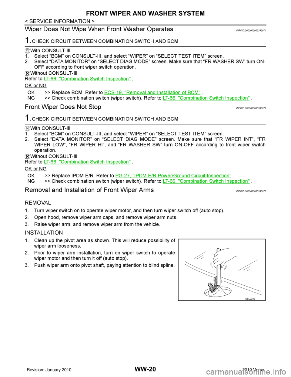
1. Clean up the pivot area as shown. This will reduce possibility of
wiper arm looseness.
2. Prior to wiper arm installation, turn on wiper switch to operate wiper motor and then turn it off (auto stop).
3. Push wiper arm onto pivot shaft, paying attention to blind spline.
SEL024J
Revision: January 20102010 Versa
Page 3726 of 3745
FRONT WIPER AND WASHER SYSTEMWW-21
< SERVICE INFORMATION >
C
DE
F
G H
I
J
L
M A
B
WW
N
O P
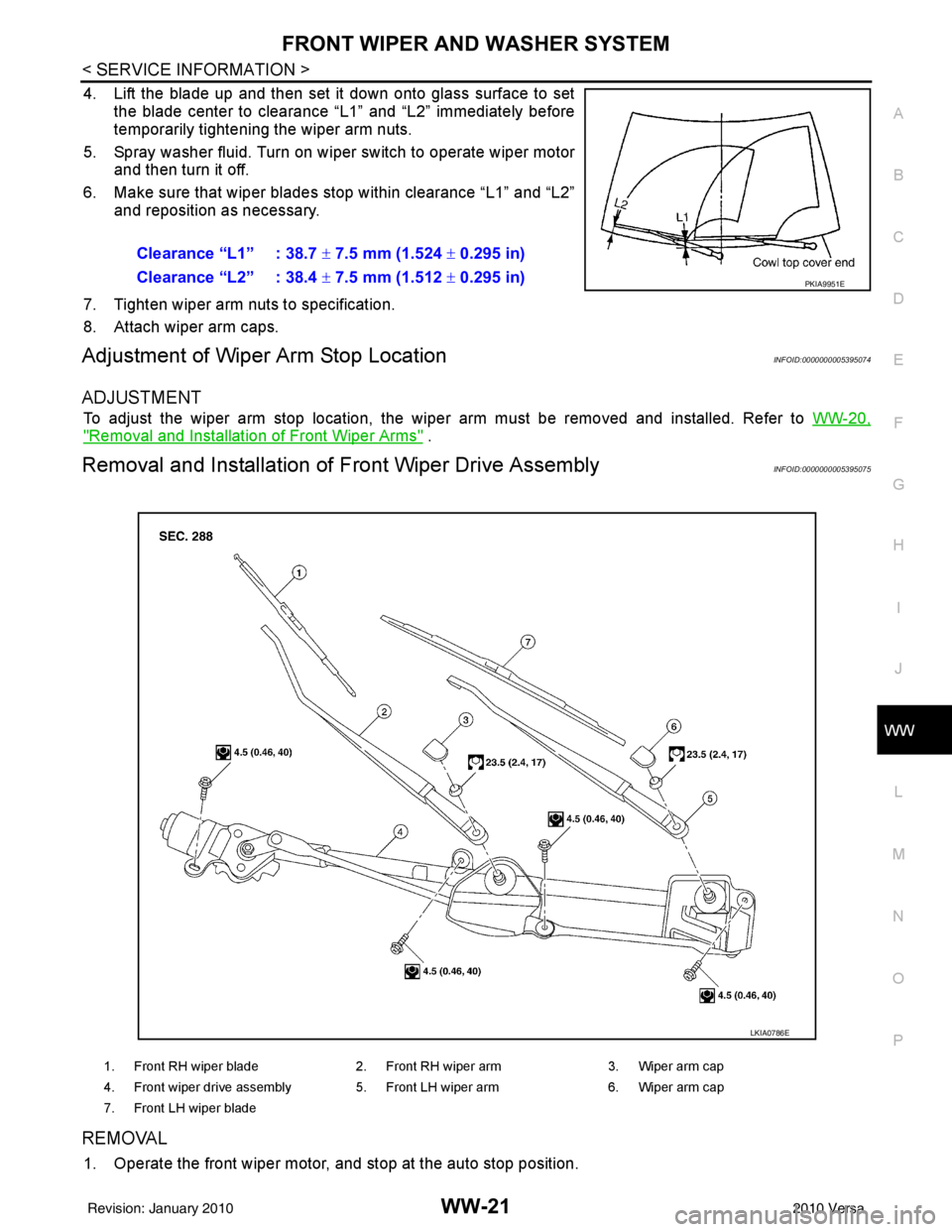
4. Lift the blade up and then set it down onto glass surface to set the blade center to clearance “L1” and “L2” immediately before
temporarily tightening the wiper arm nuts.
5. Spray washer fluid. Turn on wiper switch to operate wiper motor and then turn it off.
6. Make sure that wiper blades stop within clearance “L1” and “L2” and reposition as necessary.
7. Tighten wiper arm nuts to specification.
8. Attach wiper arm caps.
Adjustment of Wiper Arm Stop LocationINFOID:0000000005395074
ADJUSTMENT
To adjust the wiper arm stop location, the wiper arm must be removed and installed. Refer to WW-20,
"Removal and Installation of Front Wiper Arms" .
Removal and Installation of Front Wiper Drive AssemblyINFOID:0000000005395075
REMOVAL
1. Operate the front wiper motor, and stop at the auto stop position.Clearance “L1” : 38.7
± 7.5 mm (1.524 ± 0.295 in)
Clearance “L2” : 38.4 ± 7.5 mm (1.512 ± 0.295 in)
PKIA9951E
1. Front RH wiper blade 2. Front RH wiper arm 3. Wiper arm cap
4. Front wiper drive assembly 5. Front LH wiper arm 6. Wiper arm cap
7. Front LH wiper blade
LKIA0786E
Revision: January 20102010 Versa
Page 3727 of 3745
WW-22
< SERVICE INFORMATION >
FRONT WIPER AND WASHER SYSTEM
2. Remove wiper arms. Refer to WW-20, "Removal and Installation of Front Wiper Arms" .
3. Remove cowl top cover. Refer to EI-22
.
4. Disconnect wiper motor connector.
5. Remove front wiper drive assembly bolts, and remove front wiper drive assembly.
INSTALLATION
1. Install front wiper drive assembly.
2. Connect wiper motor connector. Turn wiper switch on to operate wiper motor, then turn wiper switch off
(auto stop).
3. Install cowl top cover. Refer to EI-22
.
4. Install the wiper arms. Refer to WW-20, "
Removal and Installation of Front Wiper Arms" .
Removal and Installation of Front Washer NozzleINFOID:0000000005395076
REMOVAL
1. Remove cowl top cover. Refer to EI-22, "Removal and Installation" .
2. Remove washer tube.
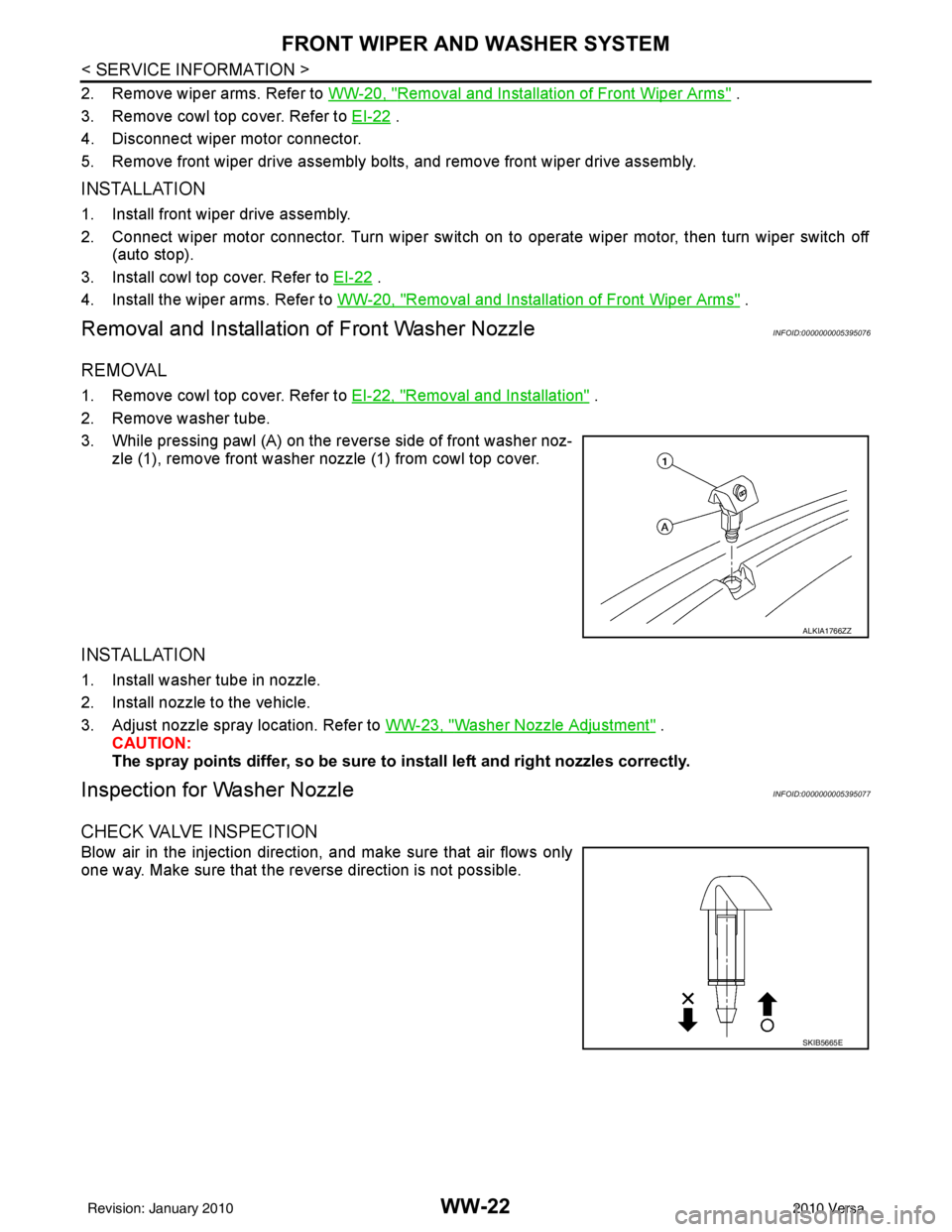
3. While pressing pawl (A) on the reverse side of front washer noz- zle (1), remove front washer nozzle (1) from cowl top cover.
INSTALLATION
1. Install washer tube in nozzle.
2. Install nozzle to the vehicle.
3. Adjust nozzle spray location. Refer to WW-23, "
Washer Nozzle Adjustment" .
CAUTION:
The spray points differ, so be sure to install left and right nozzles correctly.
Inspection for Washer NozzleINFOID:0000000005395077
CHECK VALVE INSPECTION
Blow air in the injection direction, and make sure that air flows only
one way. Make sure that the reverse direction is not possible.
ALKIA1766ZZ
SKIB5665E
Revision: January 20102010 Versa
Page 3728 of 3745
FRONT WIPER AND WASHER SYSTEMWW-23
< SERVICE INFORMATION >
C
DE
F
G H
I
J
L
M A
B
WW
N
O P
Washer Nozzle AdjustmentINFOID:0000000005395078
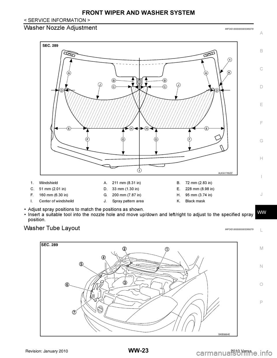
• Adjust spray positions to match the positions as shown.
• Insert a suitable tool into the nozzle hole and move up/down and left/right to adjust to the specified spray position.
Washer Tube LayoutINFOID:0000000005395079
1. Windshield A. 211 mm (8.31 in)B. 72 mm (2.83 in)
C. 51 mm (2.01 in) D. 33 mm (1.30 in)E. 228 mm (8.98 in)
F. 160 mm (6.30 in) G. 200 mm (7.87 in)H. 95 mm (3.74 in)
I. Center of windsheild J. Spray pattern areaK. Black mask
ALKIA1765ZZ
SKIB5664E
Revision: January 20102010 Versa
Page 3729 of 3745
WW-24
< SERVICE INFORMATION >
FRONT WIPER AND WASHER SYSTEM
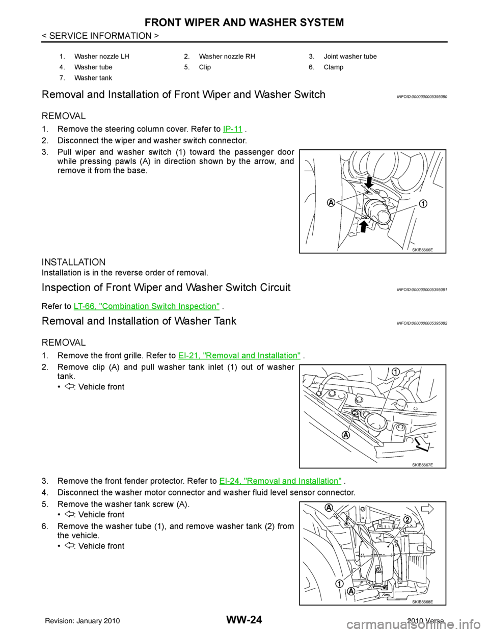
Removal and Installation of Fr ont Wiper and Washer Switch
INFOID:0000000005395080
REMOVAL
1. Remove the steering column cover. Refer to IP-11 .
2. Disconnect the wiper and washer switch connector.
3. Pull wiper and washer switch (1) toward the passenger door while pressing pawls (A) in direction shown by the arrow, and
remove it from the base.
INSTALLATION
Installation is in the reverse order of removal.
Inspection of Front Wiper and Washer Switch CircuitINFOID:0000000005395081
Refer to LT-66, "Combination Switch Inspection" .
Removal and Installation of Washer TankINFOID:0000000005395082
REMOVAL
1. Remove the front grille. Refer to EI-21, "Removal and Installation" .
2. Remove clip (A) and pull washer tank inlet (1) out of washer tank.
• : Vehicle front
3. Remove the front fender protector. Refer to EI-24, "
Removal and Installation" .
4. Disconnect the washer motor connector and washer fluid level sensor connector.
5. Remove the washer tank screw (A). • : Vehicle front
6. Remove the washer tube (1), and remove washer tank (2) from the vehicle.
• : Vehicle front
1. Washer nozzle LH 2. Washer nozzle RH3. Joint washer tube
4. Washer tube 5. Clip6. Clamp
7. Washer tank
SKIB5666E
SKIB5667E
SKIB5668E
Revision: January 20102010 Versa
Page 3730 of 3745
FRONT WIPER AND WASHER SYSTEMWW-25
< SERVICE INFORMATION >
C
DE
F
G H
I
J
L
M A
B
WW
N
O P
INSTALLATION
Installation is in the reverse order of removal.
CAUTION:
After installation, add water up to the upper level of washer tank inlet, and check for water leaks.
Removal and Installation of Front Washer MotorINFOID:0000000005395083
REMOVAL
1. Remove the front fender protector RH. Refer to EI-24 .
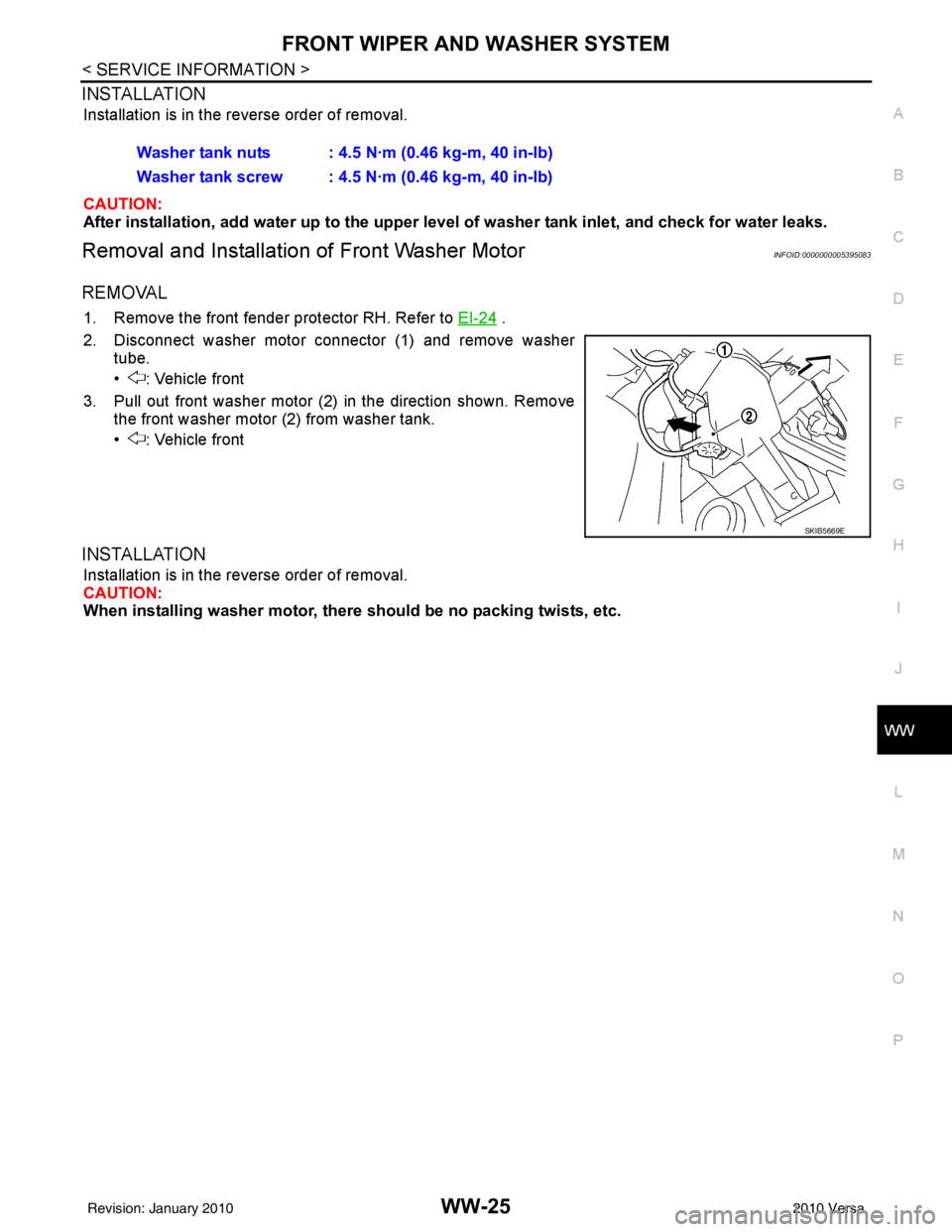
2. Disconnect washer motor connector (1) and remove washer tube.
• : Vehicle front
3. Pull out front washer motor (2) in the direction shown. Remove the front washer motor (2) from washer tank.
• : Vehicle front
INSTALLATION
Installation is in the reverse order of removal.
CAUTION:
When installing washer motor, th ere should be no packing twists, etc.
Washer tank nuts : 4.5 N·m (0.46 kg-m, 40 in-lb)
Washer tank screw : 4.5 N·m (0.46 kg-m, 40 in-lb)
SKIB5669E
Revision: January 20102010 Versa