diagram NISSAN LATIO 2010 Service Repair Manual
[x] Cancel search | Manufacturer: NISSAN, Model Year: 2010, Model line: LATIO, Model: NISSAN LATIO 2010Pages: 3745, PDF Size: 73.67 MB
Page 3691 of 3745
WT-14
< SERVICE INFORMATION >
TROUBLE DIAGNOSES
6. Inflate all tires to proper pressure. Refer to WT-28, "Tire" .
Transmitter Wake Up OperationINFOID:0000000005397099
NOTE:
This procedure must be done after replacement of a low tire pressure warning transmitter or BCM.
New replacement transmitters are provided "asleep" and must first be "woken up" using Transmitter
Activation Tool J-45295 before ID registration can be performed.
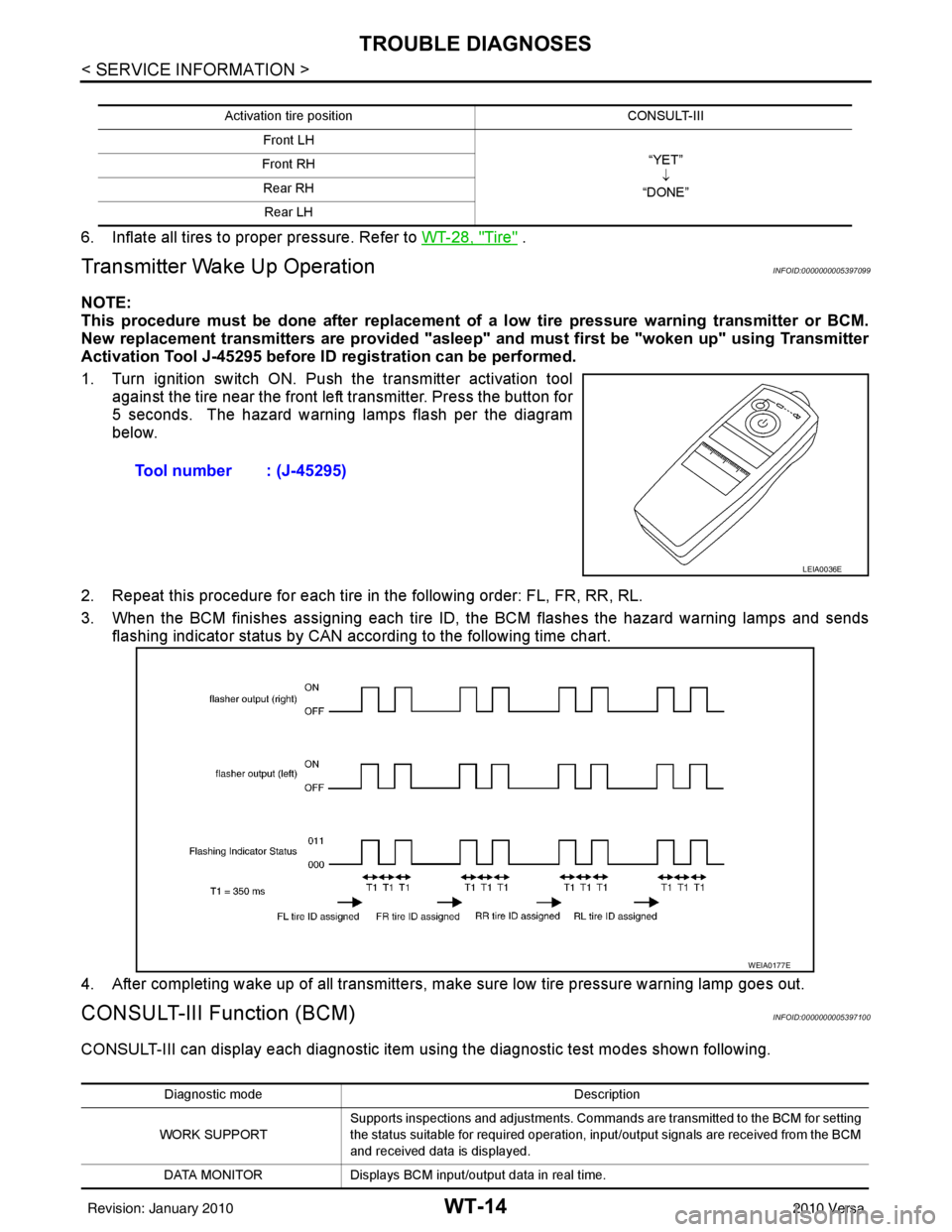
1. Turn ignition switch ON. Push the transmitter activation tool against the tire near the front left transmitter. Press the button for
5 seconds. The hazard warning lamps flash per the diagram
below.
2. Repeat this procedure for each tire in the following order: FL, FR, RR, RL.
3. When the BCM finishes assigning each tire ID, the BCM flashes the hazard warning lamps and sends flashing indicator status by CAN according to the following time chart.
4. After completing wake up of all transmitters, make sure low tire pressure warning lamp goes out.
CONSULT-III Function (BCM)INFOID:0000000005397100
CONSULT-III can display each diagnostic item us ing the diagnostic test modes shown following.
Activation tire position CONSULT-III
Front LH “YET”↓
“DONE”
Front RH
Rear RHRear LH
Tool number : (J-45295)
LEIA0036E
WEIA0177E
Diagnostic mode Description
WORK SUPPORT Supports inspections and adjustments. Commands are transmitted to the BCM for setting
the status suitable for required operation, input/output signals are received from the BCM
and received data is displayed.
DATA MONITOR Displays BCM input/output data in real time.
Revision: January 20102010 Versa
Page 3706 of 3745

WW-1
ELECTRICAL
C
DE
F
G H
I
J
L
M
SECTION WW
A
B
WW
N
O P
CONTENTS
WIPER, WASHER & HORN
SERVICE INFORMATION .. ..........................2
PRECAUTION ................................................ .....2
Precaution for Supplemental Restraint System
(SRS) "AIR BAG" and "SEAT BELT PRE-TEN-
SIONER" ............................................................. ......
2
Precaution Necessary for Steering Wheel Rota-
tion After Battery Disconnect ............................... ......
2
Precaution for Procedure without Cowl Top Cover ......3
PREPARATION ...................................................4
Special Service Tool ........................................... ......4
FRONT WIPER AND WASHER SYSTEM ..........5
Component Parts and Harness Connector Loca-
tion ...................................................................... ......
5
System Description ...................................................5
CAN Communication System Description .................7
Schematic .................................................................8
Wiring Diagram - WIPER - ........................................9
Terminal and Reference Value for BCM .................12
Terminal and Reference Value for IPDM E/R .........12
How to Proceed with Trouble Diagnosis .................12
Preliminary Check ...................................................12
CONSULT-III Function (BCM) .................................12
CONSULT-III Function (IPDM E/R) .........................13
Front Wiper Does Not Operate ...............................14
Front Wiper Does Not Return to Stop Position (Af-
ter Front Wiper Operates for 10 Seconds, They
Stop for 20 Seconds, and After Repeating the Op-
eration Five Times, They Become Inoperative) ......
16
Only Front Wiper Low Does Not Operate ...............17
Only Front Wiper High Does Not Operate ...............18
Only Front Wiper Intermittent Does Not Operate ....19
Front Wiper Intermittent Operation Switch Posi-
tion Cannot Be Adjusted .........................................
19
Wiper Does Not Wipe When Front Washer Oper-
ates .........................................................................
20
Front Wiper Does Not Stop .....................................20
Removal and Installation of Front Wiper Arms ........20
Adjustment of Wiper Arm Stop Location .............. ....21
Removal and Installation of Front Wiper Drive As-
sembly .....................................................................
21
Removal and Installation of Front Washer Nozzle ....22
Inspection for Washer Nozzle ..................................22
Washer Nozzle Adjustment ................................. ....23
Washer Tube Layout ...............................................23
Removal and Installation of Front Wiper and
Washer Switch .........................................................
24
Inspection of Front Wiper and Washer Switch Cir-
cuit ...........................................................................
24
Removal and Installation of Washer Tank ...............24
Removal and Installation of Front Washer Motor ....25
REAR WIPER AND WASHER SYSTEM ..........26
Component Parts and Harness Connector Loca-
tion ....................................................................... ....
26
System Description ..................................................26
Wiring Diagram - WIP/R - ........................................28
Terminal and Reference Value for BCM ..................30
How to Proceed with Trou ble Diagnosis ..................30
Preliminary Check ............................................... ....30
CONSULT-III Function (BCM) .................................30
Rear Wiper Does Not Operate ............................ ....30
Rear Wiper Stop Position Is Incorrect .....................31
Only Rear Wiper Does Not Operate ........................33
Only Rear Wiper Intermittent Does Not Operate .....33
Wiper Does Not Wipe When Rear Washer Oper-
ates ..........................................................................
33
Removal and Installation .........................................33
Washer Nozzle Adjustment .....................................36
POWER SOCKET .............................................37
Wiring Diagram - P/SCKT - .....................................37
Removal and Installation .........................................37
HORN ................................................................39
Wiring Diagram - HORN - ........................................39
Removal and Installation .........................................39
Revision: January 20102010 Versa
Page 3714 of 3745
FRONT WIPER AND WASHER SYSTEMWW-9
< SERVICE INFORMATION >
C
DE
F
G H
I
J
L
M A
B
WW
N
O P
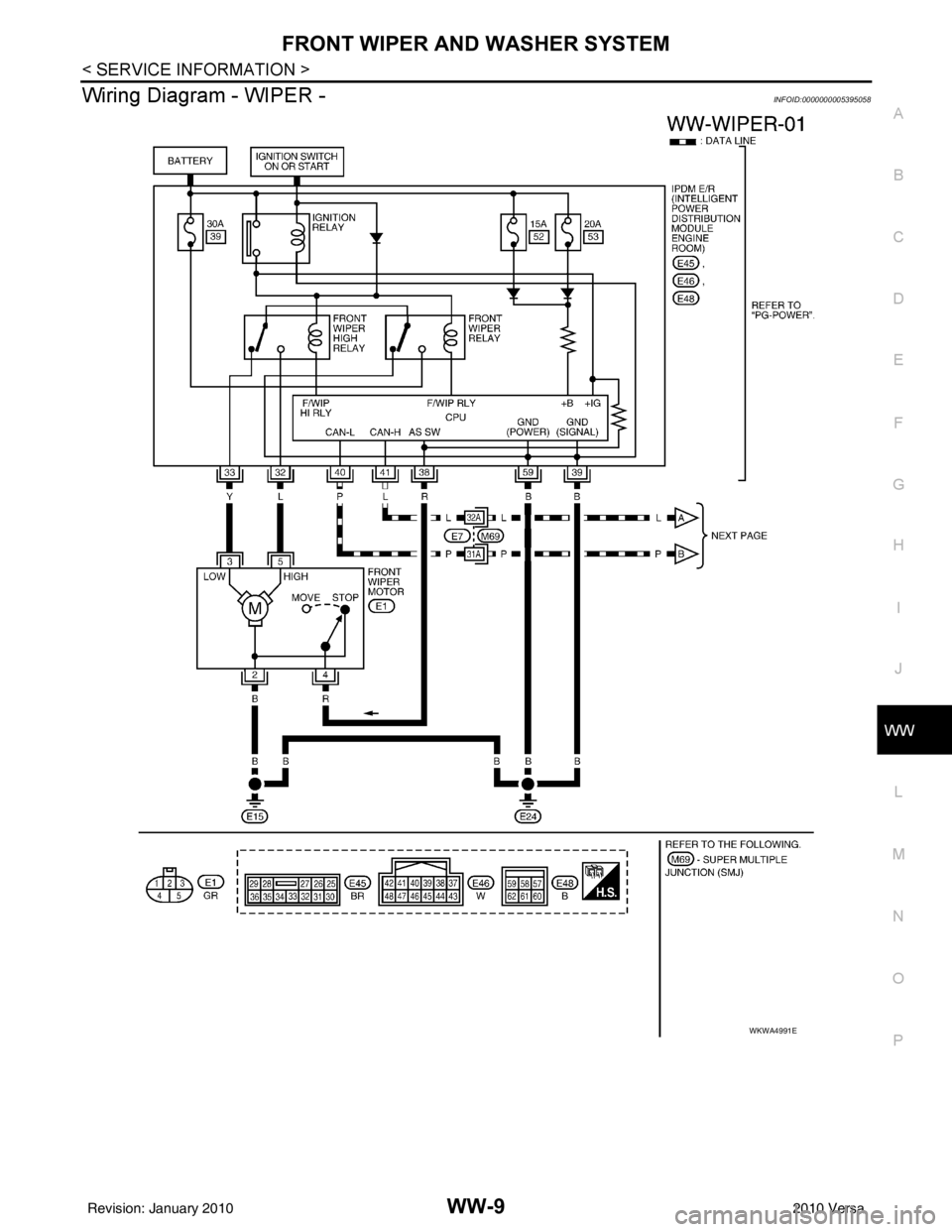
Wiring Diagram - WIPER -INFOID:0000000005395058
WKWA4991E
Revision: January 20102010 Versa
Page 3733 of 3745
WW-28
< SERVICE INFORMATION >
REAR WIPER AND WASHER SYSTEM
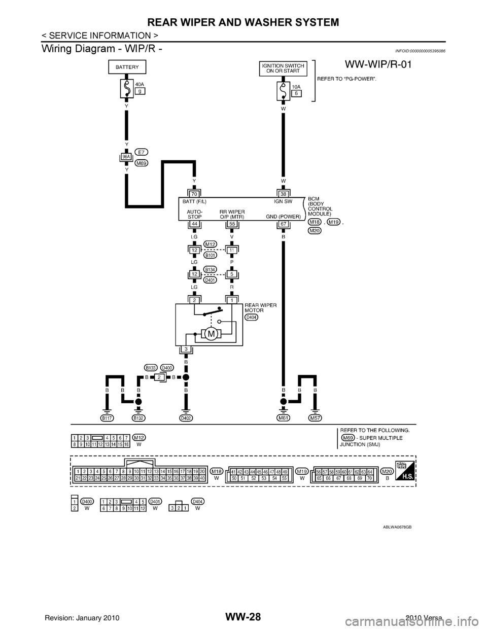
Wiring Diagram - WIP/R -
INFOID:0000000005395086
ABLWA0678GB
Revision: January 20102010 Versa
Page 3742 of 3745
POWER SOCKETWW-37
< SERVICE INFORMATION >
C
DE
F
G H
I
J
L
M A
B
WW
N
O P
POWER SOCKET
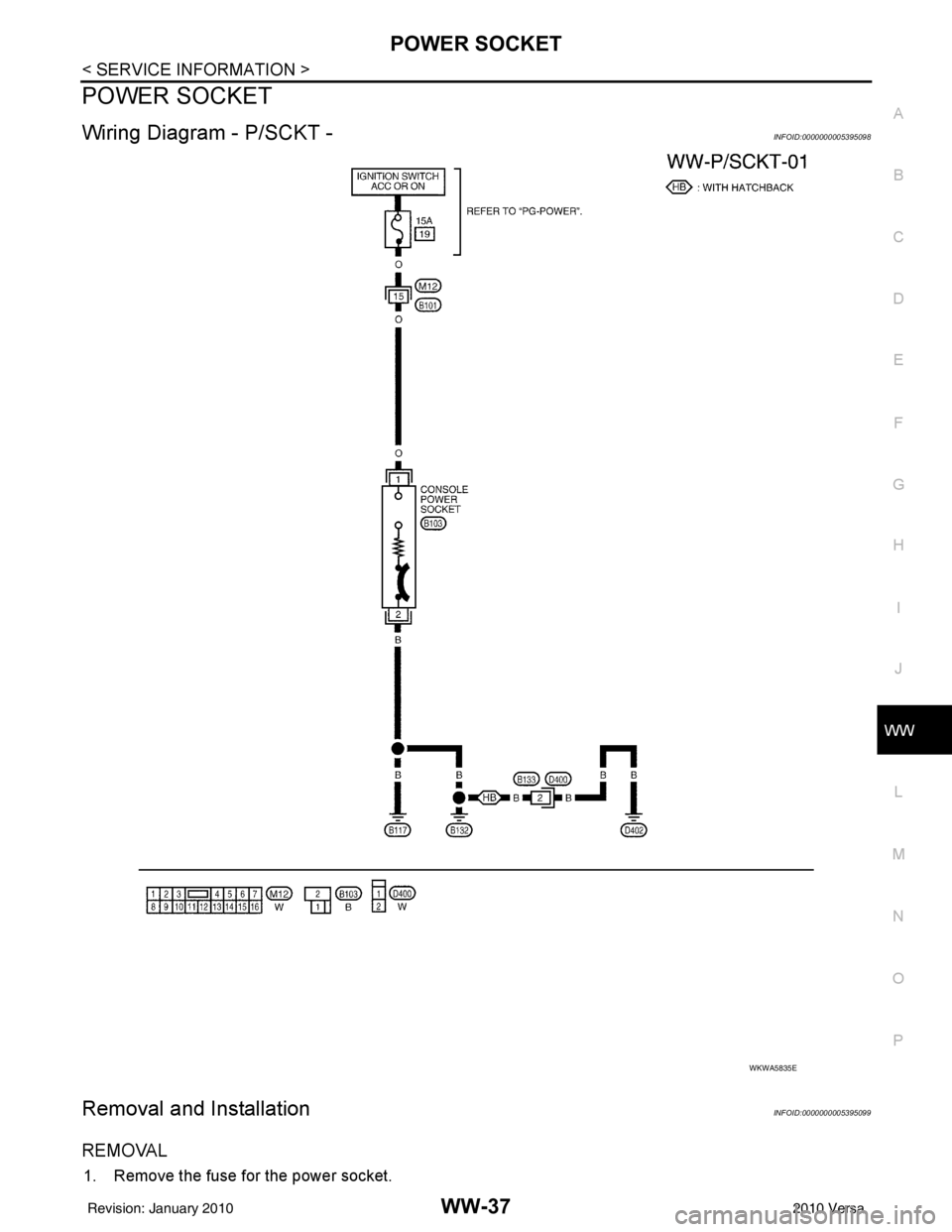
Wiring Diagram - P/SCKT -INFOID:0000000005395098
Removal and InstallationINFOID:0000000005395099
REMOVAL
1. Remove the fuse for the power socket.
WKWA5835E
Revision: January 20102010 Versa
Page 3744 of 3745
HORN
WW-39
< SERVICE INFORMATION >
C
D E
F
G H
I
J
L
M A
B
WW
N
O P
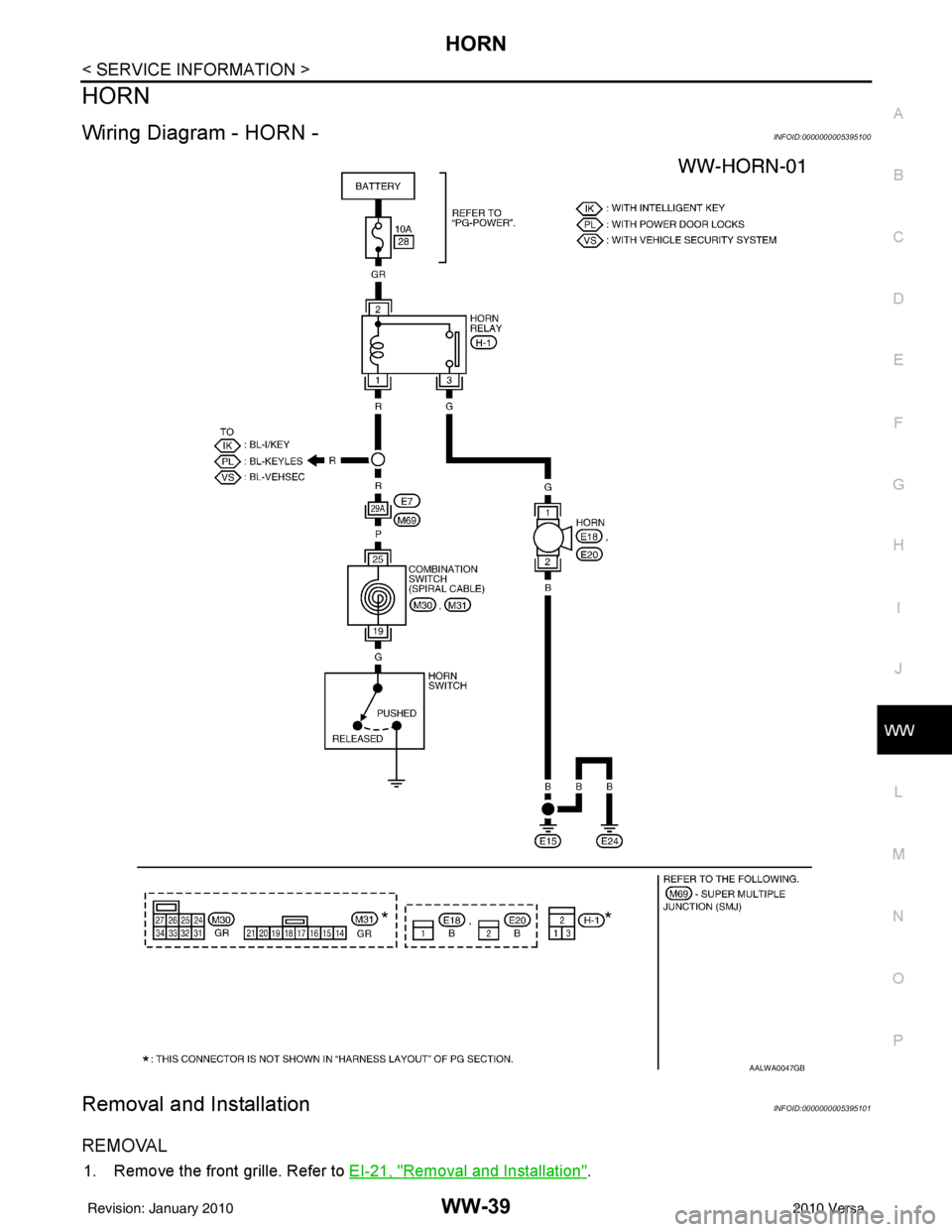
HORN
Wiring Diagram - HORN -INFOID:0000000005395100
Removal and InstallationINFOID:0000000005395101
REMOVAL
1. Remove the front grille. Refer to EI-21, "Removal and Installation".
AALWA0047GB
Revision: January 20102010 Versa