wheel bolts NISSAN LATIO 2010 Service Repair Manual
[x] Cancel search | Manufacturer: NISSAN, Model Year: 2010, Model line: LATIO, Model: NISSAN LATIO 2010Pages: 3745, PDF Size: 73.67 MB
Page 71 of 3745
AT-54
< SERVICE INFORMATION >
TROUBLE DIAGNOSIS
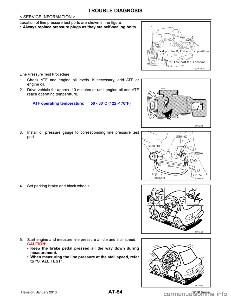
Location of line pressure test ports are shown in the figure.
•Always replace pressure plugs as they are self-sealing bolts.
Line Pressure Test Procedure
1. Check ATF and engine oil levels. If necessary, add ATF or
engine oil.
2. Drive vehicle for approx. 10 minutes or until engine oil and ATF reach operating temperature.
3. Install oil pressure gauge to corresponding line pressure test port.
4. Set parking brake and block wheels.
5. Start engine and measure line pressure at idle and stall speed. CAUTION:
• Keep the brake pedal pressed all the way down duringmeasurement.
• When measuring the line pressure at the stall speed, refer to "STALL TEST".
SCIA7187E
ATF operating temperature: 50 - 80° C (122 -176°F)
SAT647B
SCIA6528J
SAT513G
SAT493G
Revision: January 20102010 Versa
Page 874 of 3745
BR-26
< SERVICE INFORMATION >
FRONT DISC BRAKE
CLZ25VF
CAUTION:
• Clean dust on caliper and brake pad with a vacuum dust collector. Do not blow with compressed air.
• While removing brake pad or cylinder body, do not depress brake pedal because piston will pop out.
• It is not necessary to remove torque member mounting bolts and brake hose except for disassembly
or replacement of caliper assembly. In this case, hang cylinder body with a wire so that brake hose is
not under tension.
• Do not damage piston boot.
• If any shim is subject to serious corrosion, replace it with a new one.
• Keep rotor free from brake fluid.
• When replacing brake pad, replace shim with a new one.
Removal and Installation of Brake PadINFOID:0000000005396999
AD22VK
Removal
1. Partially drain brake fluid reservoir. Refer to BR-9, "Drain and Refill".
2. Remove front wheel and tire using power tools.
AWFIA0641GB
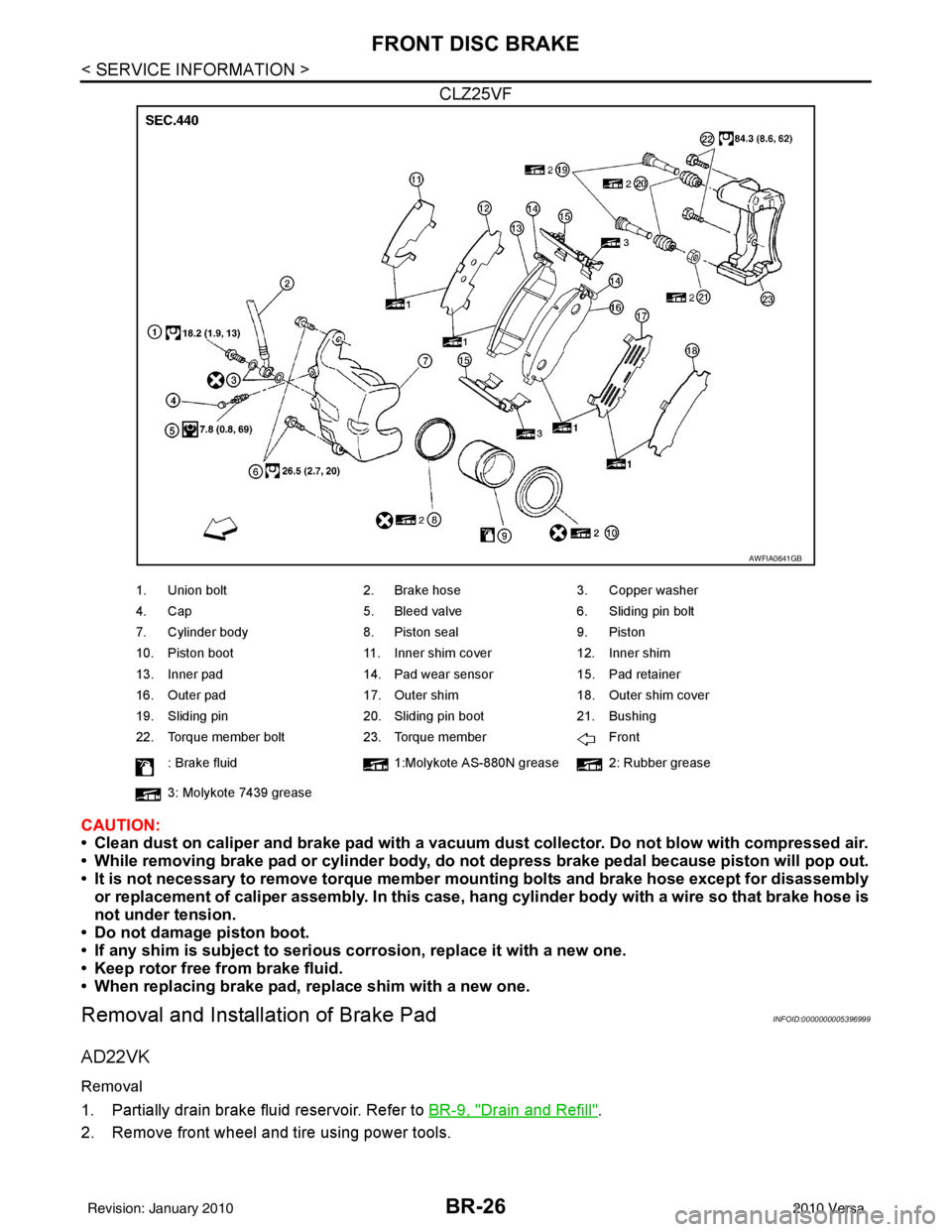
1. Union bolt 2. Brake hose3. Copper washer
4. Cap 5. Bleed valve6. Sliding pin bolt
7. Cylinder body 8. Piston seal9. Piston
10. Piston boot 11. Inner shim cover12. Inner shim
13. Inner pad 14. Pad wear sensor15. Pad retainer
16. Outer pad 17. Outer shim18. Outer shim cover
19. Sliding pin 20. Sliding pin boot21. Bushing
22. Torque member bolt 23. Torque member Front
: Brake fluid 1:Molykote AS-880N grease 2: Rubber grease
3: Molykote 7439 grease
Revision: January 20102010 Versa
Page 878 of 3745
BR-30
< SERVICE INFORMATION >
FRONT DISC BRAKE
Removal and Installation of Brake Caliper Assembly
INFOID:0000000005397000
REMOVAL
1. Remove front wheel and tire.
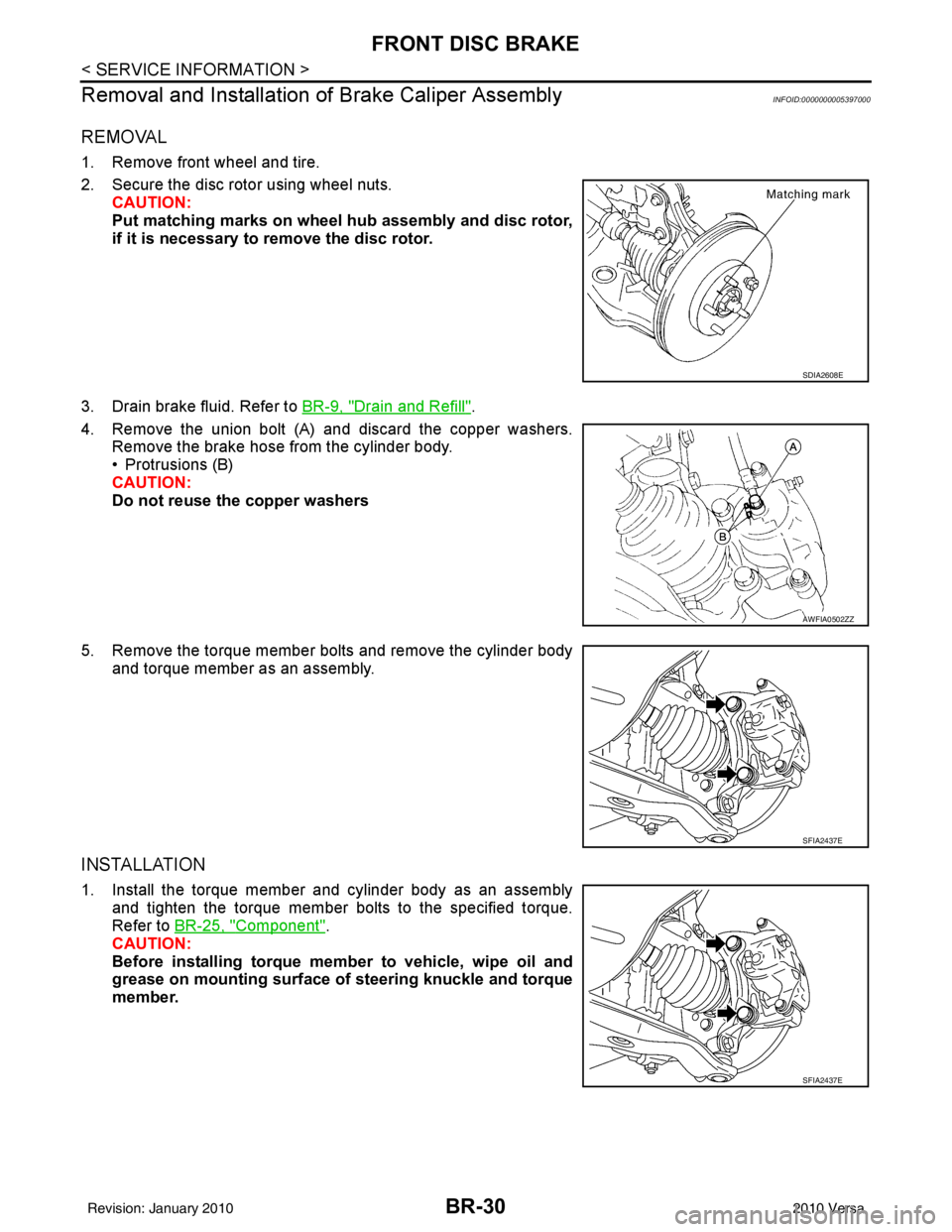
2. Secure the disc rotor using wheel nuts.
CAUTION:
Put matching marks on wheel hub assembly and disc rotor,
if it is necessary to remove the disc rotor.
3. Drain brake fluid. Refer to BR-9, "
Drain and Refill".
4. Remove the union bolt (A) and discard the copper washers. Remove the brake hose from the cylinder body.
• Protrusions (B)
CAUTION:
Do not reuse the copper washers
5. Remove the torque member bolts and remove the cylinder body and torque member as an assembly.
INSTALLATION
1. Install the torque member and cylinder body as an assemblyand tighten the torque member bolts to the specified torque.
Refer to BR-25, "
Component".
CAUTION:
Before installing torque member to vehicle, wipe oil and
grease on mounting surface of steering knuckle and torque
member.
SDIA2608E
AWFIA0502ZZ
SFIA2437E
SFIA2437E
Revision: January 20102010 Versa
Page 879 of 3745
FRONT DISC BRAKEBR-31
< SERVICE INFORMATION >
C
DE
G H
I
J
K L
M A
B
BR
N
O P
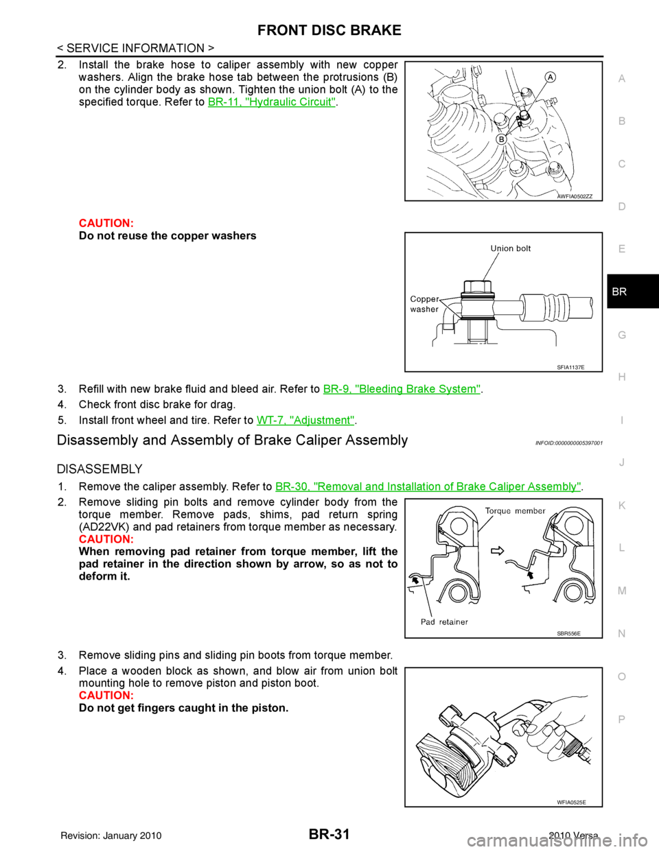
2. Install the brake hose to caliper assembly with new copper washers. Align the brake hose tab between the protrusions (B)
on the cylinder body as shown. Tighten the union bolt (A) to the
specified torque. Refer to BR-11, "
Hydraulic Circuit".
CAUTION:
Do not reuse the copper washers
3. Refill with new brake fluid and bleed air. Refer to BR-9, "
Bleeding Brake System".
4. Check front disc brake for drag.
5. Install front wheel and tire. Refer to WT-7, "
Adjustment".
Disassembly and Assembly of Brake Caliper AssemblyINFOID:0000000005397001
DISASSEMBLY
1. Remove the caliper assembly. Refer to BR-30, "Removal and Installation of Brake Caliper Assembly".
2. Remove sliding pin bolts and remove cylinder body from the torque member. Remove pads, shims, pad return spring
(AD22VK) and pad retainers from torque member as necessary.
CAUTION:
When removing pad retainer from torque member, lift the
pad retainer in the direction shown by arrow, so as not to
deform it.
3. Remove sliding pins and sliding pin boots from torque member.
4. Place a wooden block as shown, and blow air from union bolt mounting hole to remove piston and piston boot.
CAUTION:
Do not get fingers caught in the piston.
AWFIA0502ZZ
SFIA1137E
SBR556E
WFIA0525E
Revision: January 20102010 Versa
Page 880 of 3745
BR-32
< SERVICE INFORMATION >
FRONT DISC BRAKE
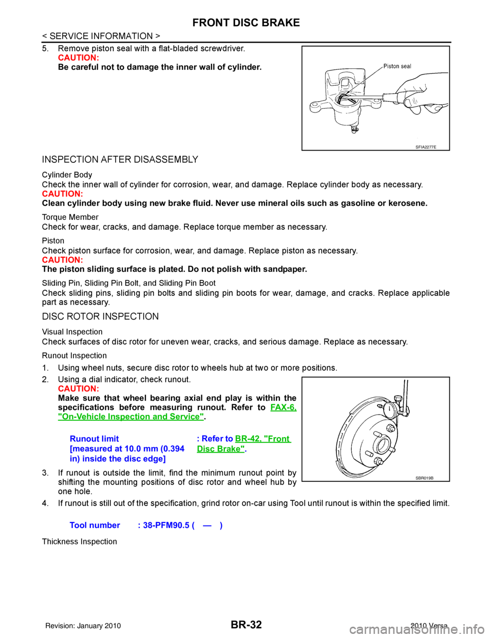
5. Remove piston seal with a flat-bladed screwdriver.CAUTION:
Be careful not to damage the inner wall of cylinder.
INSPECTION AFTER DISASSEMBLY
Cylinder Body
Check the inner wall of cylinder for corrosion, w ear, and damage. Replace cylinder body as necessary.
CAUTION:
Clean cylinder body using new brake fluid. Never use mineral oils such as gasoline or kerosene.
Torque Member
Check for wear, cracks, and damage. R eplace torque member as necessary.
Piston
Check piston surface for corrosion, wear, and damage. Replace piston as necessary.
CAUTION:
The piston sliding surface is plated. Do not polish with sandpaper.
Sliding Pin, Sliding Pin Bolt, and Sliding Pin Boot
Check sliding pins, sliding pin bolts and sliding pin boots for wear, damage, and cracks. Replace applicable
part as necessary.
DISC ROTOR INSPECTION
Visual Inspection
Check surfaces of disc rotor for uneven wear, cr acks, and serious damage. Replace as necessary.
Runout Inspection
1. Using wheel nuts, secure disc rotor to wheels hub at two or more positions.
2. Using a dial indicator, check runout.
CAUTION:
Make sure that wheel bearing axial end play is within the
specifications before measuring runout. Refer to FA X - 6 ,
"On-Vehicle Inspection and Service".
3. If runout is outside the limit, find the minimum runout point by shifting the mounting positions of disc rotor and wheel hub by
one hole.
4. If runout is still out of the specification, grind rotor on-car using Tool until runout is within the specified limit.
Thickness Inspection
SFIA2277E
Runout limit
[measured at 10.0 mm (0.394
in) inside the disc edge] : Refer to BR-42, "Front
Disc Brake".
Tool number : 38-PFM90.5 ( — )
SBR019B
Revision: January 20102010 Versa
Page 887 of 3745
REAR DRUM BRAKEBR-39
< SERVICE INFORMATION >
C
DE
G H
I
J
K L
M A
B
BR
N
O P
5. Connect the parking brake rear cable to the operating lever.
6. Install the shoe assembly. After assembly, be sure that each part is installed properly. CAUTION:
Do not damage the wheel cylinder piston boot.
7. Install the brake drum.
8. Depress brake pedal for several times (approximately 2 or 3 times).
9. Adjust clearance of brake shoe. Refer to PB-5, "
On-Vehicle Service".
10. Install rear wheel and tire. Refer to WT-7, "
Adjustment".
Removal and Installati on of Wheel CylinderINFOID:0000000005397005
REMOVAL
1. Drain the brake fluid. Refer to BR-9, "Drain and Refill".
2. Remove the rear brake shoe assembly. Refer to BR-36, "
Removal and Installation of Drum Brake Assem-
bly".
3. Remove the bleed valve.
4. Disconnect the brake tube from the wheel cylinder.
5. Remove the wheel cylinder bolts and then remove the wheel cylinder from the back plate.
INSTALLATION
Installation is in the reverse order of removal.
• Tighten bolts and bleed valve to the specified torque. Refer to BR-35, "
Component".
• Refill with new brake fluid and bleed the air. Refer to BR-9, "
Bleeding Brake System".
Disassembly and Assembly of Wheel CylinderINFOID:0000000005397006
DISASSEMBLY
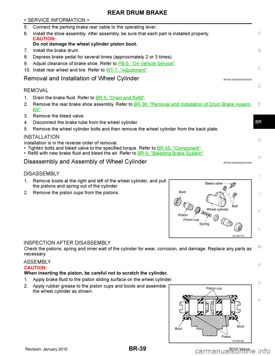
1. Remove boots at the right and left of the wheel cylinder, and pull
the pistons and spring out of the cylinder.
2. Remove the piston cups from the pistons.
INSPECTION AFTER DISASSEMBLY
Check the pistons, spring and inner wall of the cylinder for wear, corrosion, and damage. Replace any parts as
necessary.
ASSEMBLY
CAUTION:
When inserting the piston, be caref ul not to scratch the cylinder.
1. Apply brake fluid to the piston sliding surface on the wheel cylinder.
2. Apply rubber grease to the piston cups and boots and assemble the wheel cylinder as shown.
SFIA3077E
SFIA3078E
Revision: January 20102010 Versa
Page 927 of 3745
![NISSAN LATIO 2010 Service Repair Manual ACTUATOR AND ELECTRIC UNIT (ASSEMBLY)BRC-37
< SERVICE INFORMATION > [ABS]
C
D
E
G H
I
J
K L
M A
B
BRC
N
O P
ACTUATOR AND ELECTRIC UNIT (ASSEMBLY)
Removal and InstallationINFOID:0000000005397053
CAUTIO NISSAN LATIO 2010 Service Repair Manual ACTUATOR AND ELECTRIC UNIT (ASSEMBLY)BRC-37
< SERVICE INFORMATION > [ABS]
C
D
E
G H
I
J
K L
M A
B
BRC
N
O P
ACTUATOR AND ELECTRIC UNIT (ASSEMBLY)
Removal and InstallationINFOID:0000000005397053
CAUTIO](/img/5/57358/w960_57358-926.png)
ACTUATOR AND ELECTRIC UNIT (ASSEMBLY)BRC-37
< SERVICE INFORMATION > [ABS]
C
D
E
G H
I
J
K L
M A
B
BRC
N
O P
ACTUATOR AND ELECTRIC UNIT (ASSEMBLY)
Removal and InstallationINFOID:0000000005397053
CAUTION:
• Before servicing, disconnect battery negative terminal.
• To remove brake tube, use flare nut wrench to pr event flare nuts and brake tube from being dam-
aged. To install, use flare nut torque wrench, ti ghten flare nut to the specified torque. Refer to BR-11,
"Hydraulic Circuit".
• Do not apply excessive impact to ABS actuator and elect ric unit (control unit), such as dropping it.
• Do not remove and install actuator by holding harness.
• After work is completed, bleed the air from the brake hydraulic system. Refer to BR-9, "
Bleeding
Brake System".
REMOVAL
1. Disconnect the battery negative terminal.
2. Remove the cowl top. Refer to EI-22, "
Removal and Installation".
3. Disconnect ABS actuator and electric unit (control unit) connector.
4. Loosen brake tube flare nuts, then remove brake tubes from ABS actuator and electric unit (control unit).
5. Remove brake booster hose from engine. Refer to BR-23, "
Removal and Installation".
6. Remove ABS actuator and electric unit (control unit) bracket bolts.
7. Remove ABS actuator and electric unit (control unit).
1. To front right caliper 2. To rear left wheel cylinder 3. To rear right wheel cylinder
4. To front left caliper 5. From master cylinder primary side 6. From master cylinder secondary side
7. ABS actuator and electric unit (control unit) 8. Harness connector
Front
AWFIA0532GB
Revision: January 20102010 Versa
Page 979 of 3745
![NISSAN LATIO 2010 Service Repair Manual ACTUATOR AND ELECTRIC UNIT (ASSEMBLY)BRC-89
< SERVICE INFORMATION > [VDC/TCS/ABS]
C
D
E
G H
I
J
K L
M A
B
BRC
N
O P
ACTUATOR AND ELECTRIC UNIT (ASSEMBLY)
Removal and InstallationINFOID:000000000561225 NISSAN LATIO 2010 Service Repair Manual ACTUATOR AND ELECTRIC UNIT (ASSEMBLY)BRC-89
< SERVICE INFORMATION > [VDC/TCS/ABS]
C
D
E
G H
I
J
K L
M A
B
BRC
N
O P
ACTUATOR AND ELECTRIC UNIT (ASSEMBLY)
Removal and InstallationINFOID:000000000561225](/img/5/57358/w960_57358-978.png)
ACTUATOR AND ELECTRIC UNIT (ASSEMBLY)BRC-89
< SERVICE INFORMATION > [VDC/TCS/ABS]
C
D
E
G H
I
J
K L
M A
B
BRC
N
O P
ACTUATOR AND ELECTRIC UNIT (ASSEMBLY)
Removal and InstallationINFOID:0000000005612259
CAUTION:
• Before servicing, disconnect battery negative terminal.
• To remove brake tube, use flare nut wrench to pr event flare nuts and brake tube from being dam-
aged. To install, use flare nut torque wrench, ti ghten flare nut to the specified torque. Refer to BR-11,
"Hydraulic Circuit".
• Do not apply excessive impact to ABS actuator and elect ric unit (control unit), such as dropping it.
• Do not remove and install actuator by holding harness.
• After work is completed, bleed the air from the brake hydraulic system. Refer to BR-9, "
Bleeding
Brake System".
REMOVAL
1. Disconnect the battery negative terminal.
2. Remove the cowl top. Refer to EI-22, "
Removal and Installation".
3. Disconnect ABS actuator and electric unit (control unit) connector.
4. Loosen brake tube flare nuts, then remove brake tubes from ABS actuator and electric unit (control unit).
5. Remove brake booster hose from engine. Refer to BR-23, "
Removal and Installation".
6. Remove ABS actuator and electric unit (control unit) bracket bolts.
7. Remove ABS actuator and electric unit (control unit).
1. To front right caliper 2. To rear left wheel cylinder 3. To rear right wheel cylinder
4. To front left caliper 5. From master cylinder primary side 6. From master cylinder secondary side
7. ABS actuator and electric unit (control unit) 8. Harness connector
Front
AWFIA0532GB
Revision: January 20102010 Versa
Page 2441 of 3745
![NISSAN LATIO 2010 Service Repair Manual EM-82
< REMOVAL AND INSTALLATION >[HR16DE]
ENGINE ASSEMBLY
REMOVAL AND INSTALLATION
ENGINE ASSEMBLY
Exploded ViewINFOID:0000000005398075
Removal and InstallationINFOID:0000000005398076
WARNING:
• Si NISSAN LATIO 2010 Service Repair Manual EM-82
< REMOVAL AND INSTALLATION >[HR16DE]
ENGINE ASSEMBLY
REMOVAL AND INSTALLATION
ENGINE ASSEMBLY
Exploded ViewINFOID:0000000005398075
Removal and InstallationINFOID:0000000005398076
WARNING:
• Si](/img/5/57358/w960_57358-2440.png)
EM-82
< REMOVAL AND INSTALLATION >[HR16DE]
ENGINE ASSEMBLY
REMOVAL AND INSTALLATION
ENGINE ASSEMBLY
Exploded ViewINFOID:0000000005398075
Removal and InstallationINFOID:0000000005398076
WARNING:
• Situate the vehicle on a flat and solid surface.
• Place chocks at front and back of rear wheels.
• Attach proper slingers and bolts
described in PARTS CATALOG if engine slingers are not equipped.
• Always be careful to work safely, avoid forceful or uninstructed operations.
• Never start working until exhaust system and coolant are cool enough.
CAUTION:
1. Engine mounting insulator (LH) 2. Engine mounting bracket (LH) 3. Mass damper
4. Dynamic damper 5. Engine mounting insulator (RH) 6. Engine mounting stay
7. Engine mounting bracket (RH) 8. Rear engine mounting bracket 9. Rear torque rod
10. Washer 11. Engine mounting bracket (LH)
A. Front mark B. M/T models
PBIC3736E
Revision: January 20102010 Versa
Page 2443 of 3745
![NISSAN LATIO 2010 Service Repair Manual EM-84
< REMOVAL AND INSTALLATION >[HR16DE]
ENGINE ASSEMBLY
1. Remove front wheel sensor (LH and RH) for ABS from steering knuckle (if equipped). Refer to BRC-34,
"Removal and Installation" (ABS).
2. R NISSAN LATIO 2010 Service Repair Manual EM-84
< REMOVAL AND INSTALLATION >[HR16DE]
ENGINE ASSEMBLY
1. Remove front wheel sensor (LH and RH) for ABS from steering knuckle (if equipped). Refer to BRC-34,
"Removal and Installation" (ABS).
2. R](/img/5/57358/w960_57358-2442.png)
EM-84
< REMOVAL AND INSTALLATION >[HR16DE]
ENGINE ASSEMBLY
1. Remove front wheel sensor (LH and RH) for ABS from steering knuckle (if equipped). Refer to BRC-34,
"Removal and Installation" (ABS).
2. Remove brake caliper assembly with piping connected fr om steering knuckle. Temporarily secure it on the
vehicle side with a rope to avoid load on it. Refer to BR-25, "
Component".
3. Remove drive shafts (LH and RH) from steering knuckle. Refer to FA X - 9 , "
Removal and Installation (Left
Side)" and FAX-10, "Removal and Installation (Right Side)".
4. Remove exhaust front tube. Refer to EX-6, "
Component".
5. Remove rear torque rod. NOTE:
A/T models shown.
6. Remove A/T cooler hoses from transmission (if equipped).
7. Preparation for the separation work of transaxle is as follows: • Remove transaxle joint bolts which pierce at oil pan (upper) lower rear side. Refer to EM-42, "
Compo-
nent".
Removal
1. Install engine slinger to cylinder head front left side (A) and rear
right side (B) and support the engine with a hoist.
2. Lift with a hoist and secure the engine in appropriate position.
3. Use a suitable tool (A) to securely support bottom of the engine and the transaxle assembly and simultaneously adjust hoist ten-
sion.
CAUTION:
Put a piece of wood or something similar as the supporting
surface, secure a completely stable condition.
PBIC3737E
PBIC3738E
PBIC3223J
Revision: January 20102010 Versa