center console NISSAN LATIO 2011 Service Repair Manual
[x] Cancel search | Manufacturer: NISSAN, Model Year: 2011, Model line: LATIO, Model: NISSAN LATIO 2011Pages: 3787, PDF Size: 78.35 MB
Page 231 of 3787
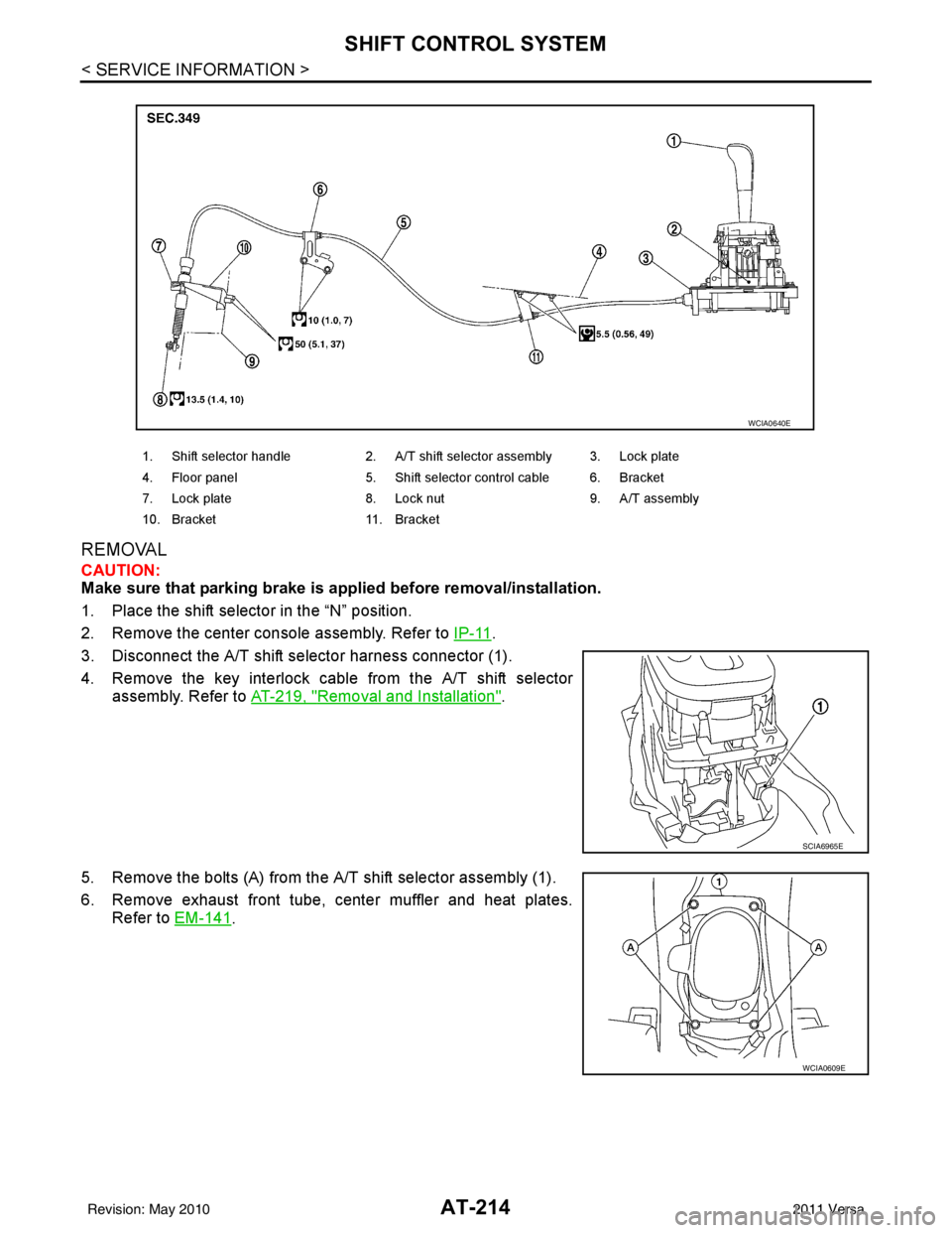
AT-214
< SERVICE INFORMATION >
SHIFT CONTROL SYSTEM
REMOVAL
CAUTION:
Make sure that parking brake is applied before removal/installation.
1. Place the shift selector in the “N” position.
2. Remove the center console assembly. Refer to IP-11
.
3. Disconnect the A/T shift selector harness connector (1).
4. Remove the key interlock cable from the A/T shift selector assembly. Refer to AT-219, "
Removal and Installation".
5. Remove the bolts (A) from the A/T shift selector assembly (1).
6. Remove exhaust front tube, center muffler and heat plates. Refer to EM-141
.
1. Shift selector handle 2. A/T shift selector assembly 3. Lock plate
4. Floor panel 5. Shift selector control cable 6. Bracket
7. Lock plate 8. Lock nut 9. A/T assembly
10. Bracket 11. Bracket
WCIA0640E
SCIA6965E
WCIA0609E
Revision: May 2010 2011 Versa
Page 236 of 3787
KEY INTERLOCK CABLEAT-219
< SERVICE INFORMATION >
DE
F
G H
I
J
K L
M A
B
AT
N
O P
KEY INTERLOCK CABLE
Removal and InstallationINFOID:0000000005928277
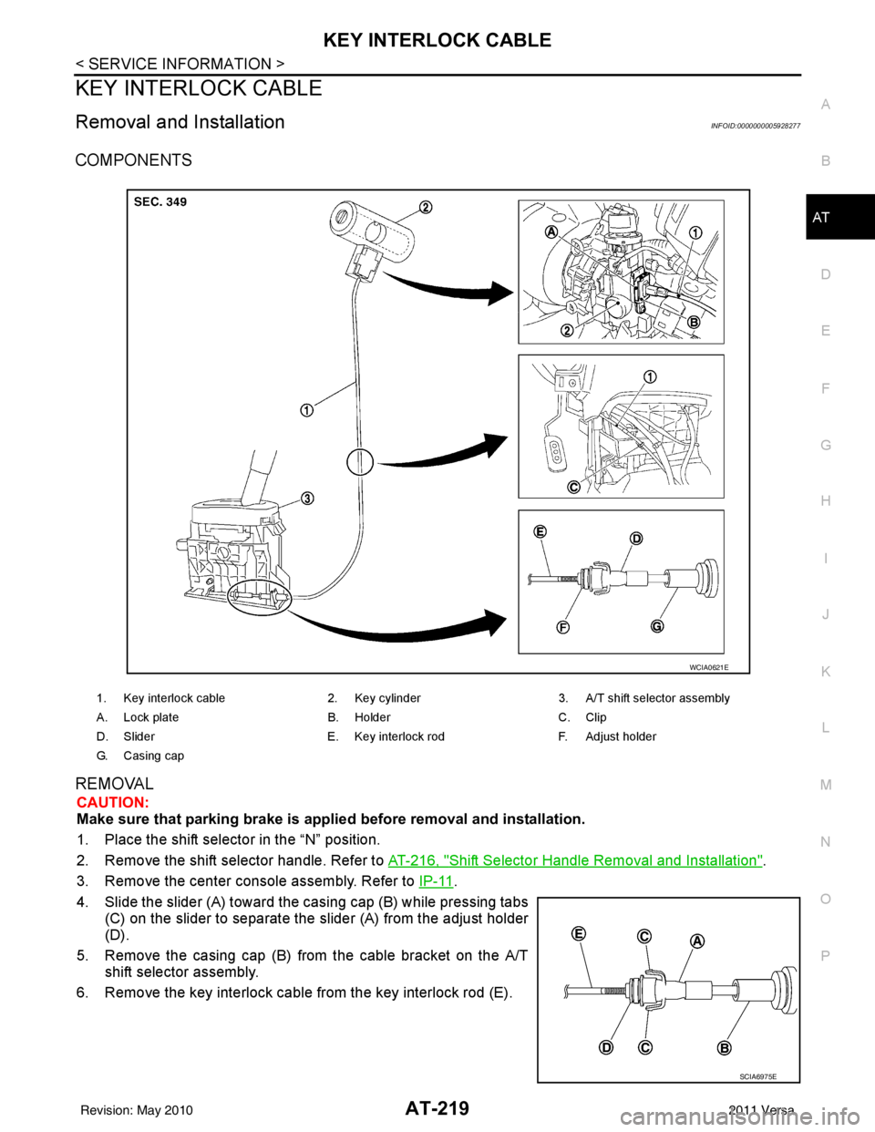
COMPONENTS
REMOVAL
CAUTION:
Make sure that parking brake is applie d before removal and installation.
1. Place the shift selector in the “N” position.
2. Remove the shift selector handle. Refer to AT-216, "
Shift Selector Handle Removal and Installation".
3. Remove the center console assembly. Refer to IP-11
.
4. Slide the slider (A) toward the casing cap (B) while pressing tabs (C) on the slider to separate the slider (A) from the adjust holder
(D).
5. Remove the casing cap (B) from the cable bracket on the A/T shift selector assembly.
6. Remove the key interlock cable from the key interlock rod (E).
1. Key interlock cable 2. Key cylinder3. A/T shift selector assembly
A. Lock plate B. HolderC. Clip
D. Slider E. Key interlock rodF. Adjust holder
G. C a s i n g c a p
WCIA0621E
SCIA6975E
Revision: May 2010 2011 Versa
Page 238 of 3787
KEY INTERLOCK CABLEAT-221
< SERVICE INFORMATION >
DE
F
G H
I
J
K L
M A
B
AT
N
O P
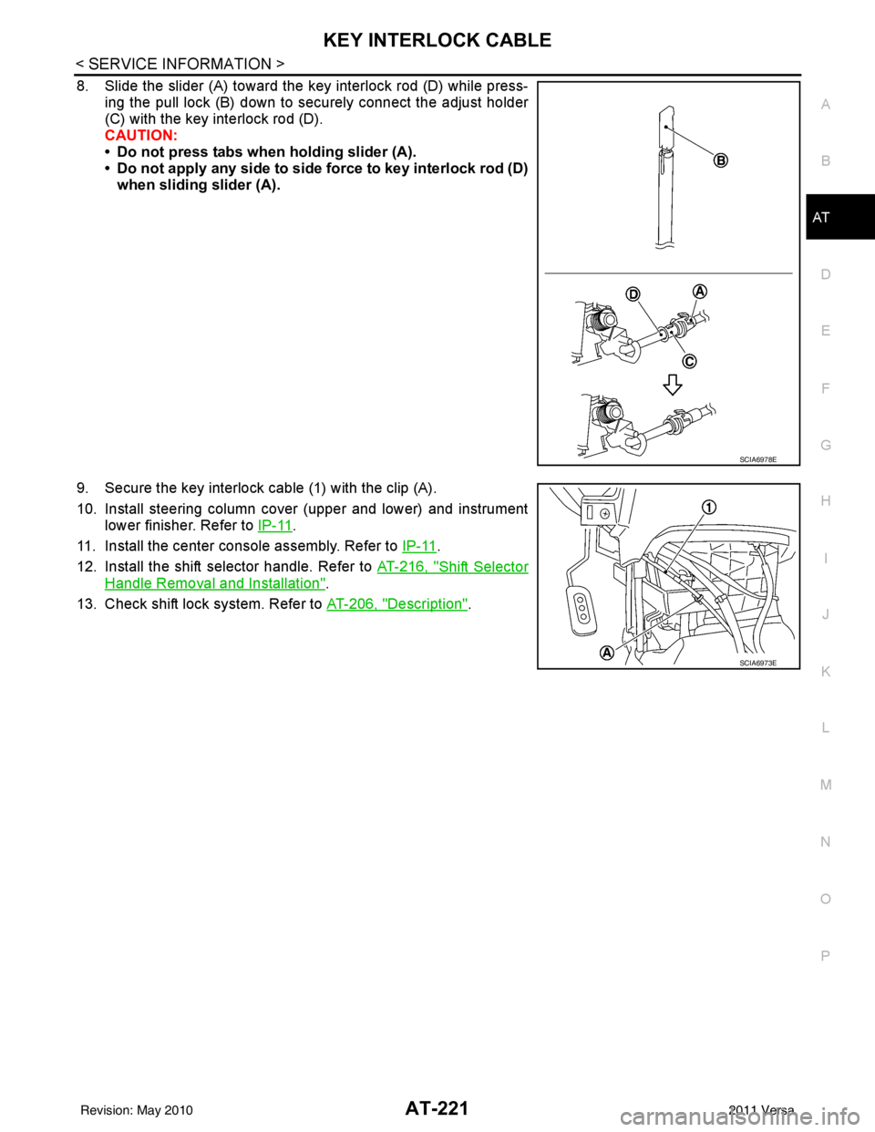
8. Slide the slider (A) toward the key interlock rod (D) while press- ing the pull lock (B) down to securely connect the adjust holder
(C) with the key interlock rod (D).
CAUTION:
• Do not press tabs when holding slider (A).
• Do not apply any side to side force to key interlock rod (D)when sliding slider (A).
9. Secure the key interlock cable (1) with the clip (A).
10. Install steering column cover (upper and lower) and instrument lower finisher. Refer to IP-11
.
11. Install the center console assembly. Refer to IP-11
.
12. Install the shift selector handle. Refer to AT-216, "
Shift Selector
Handle Removal and Installation".
13. Check shift lock system. Refer to AT-206, "
Description".
SCIA6978E
SCIA6973E
Revision: May 2010 2011 Versa
Page 519 of 3787
SQUEAK AND RATTLE TROUBLE DIAGNOSESBL-9
< SERVICE INFORMATION >
C
DE
F
G H
J
K L
M A
B
BL
N
O P
SILICONE GREASE
Used instead of UHMW tape that will be visible or not fit.
Note: Will only last a few months.
SILICONE SPRAY
Use when grease cannot be applied.
DUCT TAPE
Use to eliminate movement.
CONFIRM THE REPAIR
Confirm that the cause of a noise is repaired by test driving the vehicle. Operate the vehicle under the same
conditions as when the noise originally occurred. Refer to the notes on the Diagnostic Worksheet.
Generic Squeak and Rattle TroubleshootingINFOID:0000000005929274
Refer to Table of Contents for specific component removal and installation information.
INSTRUMENT PANEL
Most incidents are caused by contact and movement between:
1. The cluster lid A and instrument panel
2. Acrylic lens and combination meter housing
3. Instrument panel to front pillar garnish
4. Instrument panel to windshield
5. Instrument panel mounting pins
6. Wiring harnesses behind the combination meter
7. A/C defroster duct and duct joint
These incidents can usually be located by tapping or moving the components to duplicate the noise or by
pressing on the components while driving to stop the noi se. Most of these incidents can be repaired by apply-
ing felt cloth tape or silicone spray (in hard to reach areas). Urethane pads can be used to insulate wiring har-
ness.
CAUTION:
Do not use silicone spray to isolate a squeak or ra ttle. If you saturate the area with silicone, you will
not be able to recheck the repair.
CENTER CONSOLE
Components to pay attention to include:
1. Shift selector cover to finisher
2. A/C control unit and cluster lid C
3. Wiring harnesses behind audio and A/C control unit
The instrument panel repair and isolation pr ocedures also apply to the center console.
DOORS
Pay attention to the:
1. Finisher and inner panel making a slapping noise
2. Inside handle escutcheon to door finisher
3. Wiring harnesses tapping
4. Door striker out of alignment causing a popping noise on starts and stops
Tapping or moving the components or pressing on them while driving to duplicate the conditions can isolate
many of these incidents. You can usually insulate the ar eas with felt cloth tape or insulator foam blocks from
the NISSAN Squeak and Rattle Kit (J-43980) to repair the noise.
TRUNK
Trunk noises are often caused by a loose jack or loose items put into the trunk by the owner.
In addition look for:
1. Trunk lid bumpers out of adjustment
2. Trunk lid striker out of adjustment
3. The trunk lid torsion bars knocking together
4. A loose license plate or bracket
Revision: May 2010 2011 Versa
Page 1216 of 3787
![NISSAN LATIO 2011 Service Repair Manual SHIFT CONTROL SYSTEMCVT-161
< SERVICE INFORMATION > [RE0F08B]
D
E
F
G H
I
J
K L
M A
B
CVT
N
O P
REMOVAL
CAUTION:
Make sure that parking brake is applie d before removal and installation.
1. Place the NISSAN LATIO 2011 Service Repair Manual SHIFT CONTROL SYSTEMCVT-161
< SERVICE INFORMATION > [RE0F08B]
D
E
F
G H
I
J
K L
M A
B
CVT
N
O P
REMOVAL
CAUTION:
Make sure that parking brake is applie d before removal and installation.
1. Place the](/img/5/57357/w960_57357-1215.png)
SHIFT CONTROL SYSTEMCVT-161
< SERVICE INFORMATION > [RE0F08B]
D
E
F
G H
I
J
K L
M A
B
CVT
N
O P
REMOVAL
CAUTION:
Make sure that parking brake is applie d before removal and installation.
1. Place the shift selector in the “N” position.
2. Remove the center console assembly. Refer to IP-11
.
3. Disconnect the CVT shift selector harness connector (1).
4. Remove the key interlock cable from the CVT shift selector assembly. Refer to CVT-166, "
Removal and Installation".
5. Remove the bolts (A) from the CVT shift selector assembly (1).
6. Remove exhaust front tube, center muffler and heat plates. Refer to EM-141
.
1. Shift selector handle 2. CVT shift selector assembly 3. Lock plate
4. Bracket 5. Control cable6. Bracket
7. Lock plate 8. Bracket9. Transaxle assembly
A. Floor
WCIA0639E
SCIA6965E
WCIA0609E
Revision: May 2010 2011 Versa
Page 1221 of 3787
![NISSAN LATIO 2011 Service Repair Manual CVT-166
< SERVICE INFORMATION >[RE0F08B]
KEY INTERLOCK CABLE
KEY INTERLOCK CABLE
Removal and InstallationINFOID:0000000005928967
COMPONENTS
REMOVAL
Refer to the figure for key interlock cable removal NISSAN LATIO 2011 Service Repair Manual CVT-166
< SERVICE INFORMATION >[RE0F08B]
KEY INTERLOCK CABLE
KEY INTERLOCK CABLE
Removal and InstallationINFOID:0000000005928967
COMPONENTS
REMOVAL
Refer to the figure for key interlock cable removal](/img/5/57357/w960_57357-1220.png)
CVT-166
< SERVICE INFORMATION >[RE0F08B]
KEY INTERLOCK CABLE
KEY INTERLOCK CABLE
Removal and InstallationINFOID:0000000005928967
COMPONENTS
REMOVAL
Refer to the figure for key interlock cable removal procedure.
CAUTION:
Make sure that parking brake is applied before removal/installation.
1. Place the shift selector in the "N" position.
2. Remove the center console assembly. Refer to
IP-11
.
3. Slide the slider (A) toward the casing cap (B) while pressing tabs (C) on the slider to separate the slider (A) from the adjust holder
(D).
4. Remove the casing cap (B) from the cable bracket on the CVT shift selector assembly.
5. Remove the key interlock cable from the key interlock rod (E).
1. Key interlock cable 2. Key cylinder 3. CVT shift selector assembly
A. Lock plate B. HolderC. Clip
D. Slider E. Key interlock rod F. Adjust holder
G. C a s i n g c a p
WCIA0621E
SCIA6975E
Revision: May 2010 2011 Versa
Page 1223 of 3787
![NISSAN LATIO 2011 Service Repair Manual CVT-168
< SERVICE INFORMATION >[RE0F08B]
KEY INTERLOCK CABLE
8. Slide the slider (A) toward the key interlock rod (D) while press-
ing the pull lock (B) down to securely connect the adjust holder
(C) NISSAN LATIO 2011 Service Repair Manual CVT-168
< SERVICE INFORMATION >[RE0F08B]
KEY INTERLOCK CABLE
8. Slide the slider (A) toward the key interlock rod (D) while press-
ing the pull lock (B) down to securely connect the adjust holder
(C)](/img/5/57357/w960_57357-1222.png)
CVT-168
< SERVICE INFORMATION >[RE0F08B]
KEY INTERLOCK CABLE
8. Slide the slider (A) toward the key interlock rod (D) while press-
ing the pull lock (B) down to securely connect the adjust holder
(C) with the key interlock rod (D).
CAUTION:
• Do not press tabs when holding slider (A).
• Do not apply any side to side force to key interlock rod (D)when sliding slider (A).
9. Secure the key interlock cable (1) with the clip (A).
10. Install steering column cover (upper and lower) and instrument lower finisher. Refer to IP-11
.
11. Install the center console assembly. Refer to IP-11
.
12. Install the shift selector handle. Refer to CVT-163, "
Shift Selec-
tor Handle Removal and Installation".
13. Check shift lock system. Refer to CVT-153, "
Description".
SCIA6978E
SCIA6973E
Revision: May 2010 2011 Versa
Page 2338 of 3787

EI-8
< SYMPTOM DIAGNOSIS >
SQUEAK AND RATTLE TROUBLE DIAGNOSIS
The following materials, not found in the kit, can also be used to repair squeaks and rattles.
UHMW (TEFLON) TAPE
Insulates where slight movement is present. Ideal for instrument panel applications.
SILICONE GREASE
Used in place of UHMW tape that will be visible or not fit.
Note: Will only last a few months.
SILICONE SPRAY
Use when grease cannot be applied.
DUCT TAPE
Use to eliminate movement.
CONFIRM THE REPAIR
Confirm that the cause of a noise is repaired by test driving the vehicle. Operate the vehicle under the same
conditions as when the noise originally occurred. Refer to the notes on the Diagnostic Worksheet.
Generic Squeak and Rattle TroubleshootingINFOID:0000000005929551
Refer to Table of Contents for specific component removal and installation information.
INSTRUMENT PANEL
Most incidents are caused by contact and movement between:
1. The cluster lid A and instrument panel
2. Acrylic lens and combination meter housing
3. Instrument panel to front pillar garnish
4. Instrument panel to windshield
5. Instrument panel pins
6. Wiring harnesses behind the combination meter
7. A/C defroster duct and duct joint
These incidents can usually be located by tapping or moving the components to duplicate the noise or by
pressing on the components while driving to stop the noise. Most of these incidents can be repaired by apply-
ing felt cloth tape or silicone spray (in hard to reach areas). Urethane pads can be used to insulate wiring har-
ness.
CAUTION:
Do not use silicone spray to isolate a squeak or rattle. If you saturate the ar ea with silicone, you will
not be able to recheck the repair.
CENTER CONSOLE
Components to pay attention to include:
1. Shift selector assembly cover to finisher
2. A/C control unit and cluster lid C
3. Wiring harnesses behind audio and A/C control unit
The instrument panel repair and isolation pr ocedures also apply to the center console.
DOORS
Pay attention to the:
1. Finisher and inner panel making a slapping noise
2. Inside handle escutcheon to door finisher
3. Wiring harnesses tapping
4. Door striker out of alignment causing a popping noise on starts and stops
Tapping or moving the components or pressing on them wh ile driving to duplicate the conditions can isolate
many of these incidents. You can usually insulate the areas with felt cloth tape or insulator foam blocks from
the NISSAN Squeak and Rattle Kit (J-43980) to repair the noise.
TRUNK
Trunk noises are often caused by a loose jack or loose items put into the trunk by the owner.
In addition look for:
1. Trunk lid bumpers out of adjustment
2. Trunk lid striker out of adjustment
Revision: May 2010 2011 Versa
Page 2378 of 3787
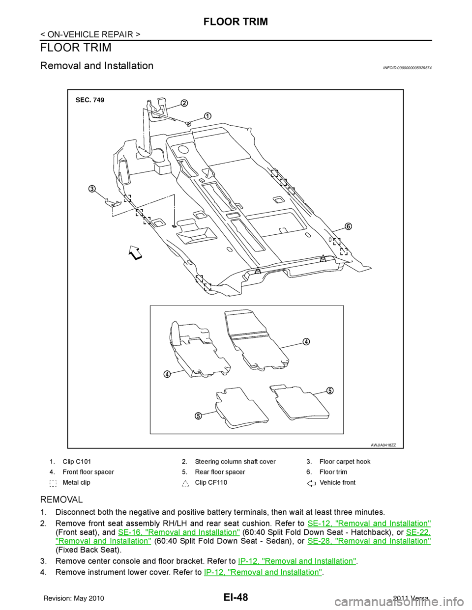
EI-48
< ON-VEHICLE REPAIR >
FLOOR TRIM
FLOOR TRIM
Removal and InstallationINFOID:0000000005929574
REMOVAL
1. Disconnect both the negative and positive battery terminals, then wait at least three minutes.
2. Remove front seat assembly RH/LH and rear seat cushion. Refer to SE-12, "
Removal and Installation"
(Front seat), and SE-16, "Removal and Installation" (60:40 Split Fold Down Seat - Hatchback), or SE-22,
"Removal and Installation" (60:40 Split Fold Down Seat - Sedan), or SE-28, "Removal and Installation"
(Fixed Back Seat).
3. Remove center console and floor bracket. Refer to IP-12, "
Removal and Installation".
4. Remove instrument lower cover. Refer to IP-12, "
Removal and Installation".
1. Clip C1012. Steering column shaft cover 3. Floor carpet hook
4. Front floor spacer 5. Rear floor spacer6. Floor trim
Metal clip Clip CF110Vehicle front
AWJIA0418ZZ
Revision: May 2010 2011 Versa
Page 2382 of 3787
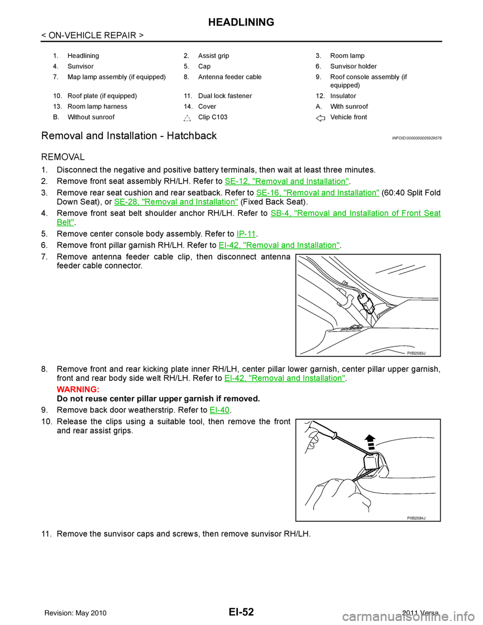
EI-52
< ON-VEHICLE REPAIR >
HEADLINING
Removal and Installation - Hatchback
INFOID:0000000005929576
REMOVAL
1. Disconnect the negative and positive battery termi nals, then wait at least three minutes.
2. Remove front seat assembly RH/LH. Refer to SE-12, "
Removal and Installation".
3. Remove rear seat cushion and rear seatback. Refer to SE-16, "
Removal and Installation" (60:40 Split Fold
Down Seat), or SE-28, "
Removal and Installation" (Fixed Back Seat).
4. Remove front seat belt shoulder anchor RH/LH. Refer to SB-4, "
Removal and Installation of Front Seat
Belt".
5. Remove center console body assembly. Refer to IP-11
.
6. Remove front pillar garnish RH/LH. Refer to EI-42, "
Removal and Installation".
7. Remove antenna feeder cable clip, then disconnect antenna feeder cable connector.
8. Remove front and rear kicking plate inner RH/LH, center pillar lower garnish, center pillar upper garnish, front and rear body side welt RH/LH. Refer to EI-42, "
Removal and Installation".
WARNING:
Do not reuse center pillar upper garnish if removed.
9. Remove back door weatherstrip. Refer to EI-40
.
10. Release the clips using a suitable tool, then remove the front and rear assist grips.
11. Remove the sunvisor caps and screws, then remove sunvisor RH/LH.
1. Headlining 2. Assist grip 3. Room lamp
4. Sunvisor 5. Cap 6. Sunvisor holder
7. Map lamp assembly (if equipped) 8. Antenna feeder cable 9. Roof console assembly (if
equipped)
10. Roof plate (if equipped) 11. Dual lock fastener 12. Insulator
13. Room lamp harness 14. Cover A. With sunroof
B. Without sunroof Clip C103Vehicle front
PIIB2583J
PIIB2584J
Revision: May 2010 2011 Versa