fuse NISSAN LATIO 2011 Service Repair Manual
[x] Cancel search | Manufacturer: NISSAN, Model Year: 2011, Model line: LATIO, Model: NISSAN LATIO 2011Pages: 3787, PDF Size: 78.35 MB
Page 3125 of 3787
INTERIOR ROOM LAMPLT-93
< SERVICE INFORMATION >
C
DE
F
G H
I
J
L
M A
B
LT
N
O P
INTERIOR ROOM LAMP
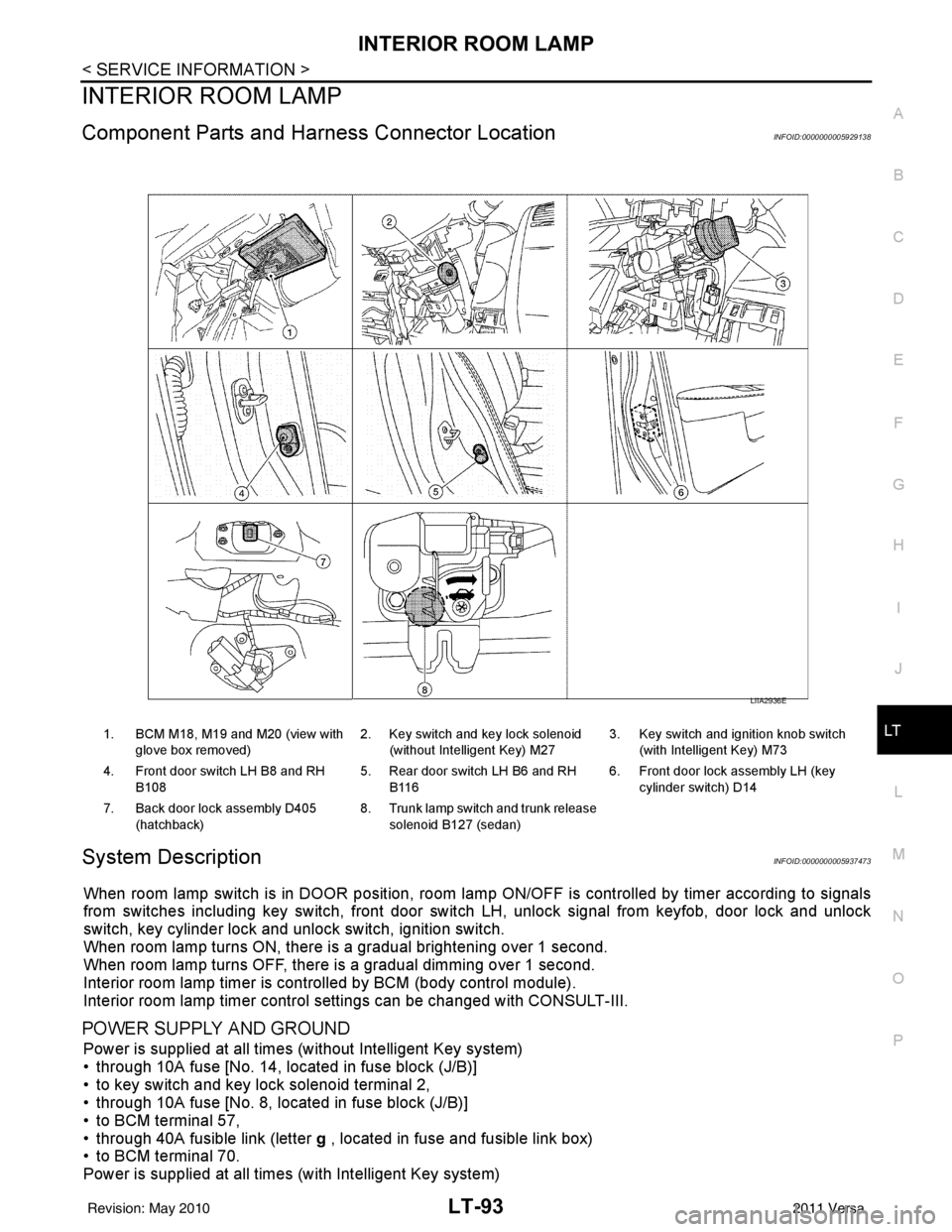
Component Parts and Har ness Connector LocationINFOID:0000000005929138
System DescriptionINFOID:0000000005937473
When room lamp switch is in DOOR position, room la mp ON/OFF is controlled by timer according to signals
from switches including key switch, front door switch LH, unlock signal from keyfob, door lock and unlock
switch, key cylinder lock and unlock switch, ignition switch.
When room lamp turns ON, there is a gradual brightening over 1 second.
When room lamp turns OFF, there is a gradual dimming over 1 second.
Interior room lamp timer is controlled by BCM (body control module).
Interior room lamp timer control settings can be changed with CONSULT-III.
POWER SUPPLY AND GROUND
Power is supplied at all times (without Intelligent Key system)
• through 10A fuse [No. 14, located in fuse block (J/B)]
• to key switch and key lock solenoid terminal 2,
• through 10A fuse [No. 8, located in fuse block (J/B)]
• to BCM terminal 57,
• through 40A fusible link (letter g , located in fuse and fusible link box)
• to BCM terminal 70.
Power is supplied at all times (with Intelligent Key system)
1. BCM M18, M19 and M20 (view with
glove box removed) 2. Key switch and key lock solenoid
(without Intelligent Key) M27 3. Key switch and ignition knob switch
(with Intelligent Key) M73
4. Front door switch LH B8 and RH B108 5. Rear door switch LH B6 and RH
B116 6. Front door lock assembly LH (key
cylinder switch) D14
7. Back door lock assembly D405 (hatchback) 8. Trunk lamp switch and trunk release
solenoid B127 (sedan)
LIIA2936E
Revision: May 2010 2011 Versa
Page 3126 of 3787

LT-94
< SERVICE INFORMATION >
INTERIOR ROOM LAMP
• through 10A fuse (No. 31, located in fuse and fusible link box)
• to key switch and ignition knob switch terminals 2 and 4,
• through 10A fuse [No. 8, located in fuse block (J/B)]
• to BCM terminal 57,
• through 40A fusible link (letter g , located in fuse and fusible link box)
• to BCM terminal 70.
When key is inserted in the key switch and key lock so lenoid, power is supplied (without Intelligent Key sys-
tem)
• through key switch and key lock solenoid terminal 1
• to BCM terminal 37.
When key is inserted in the key switch and ignition knob switch, power is supplied (with Intelligent Key system)
• through key switch and ignition knob switch terminal 1
• to BCM terminal 37.
When ignition knob switch is pushed, power is supplied (with Intelligent Key system)
• through key switch and ignition knob switch terminal 3
• to Intelligent Key unit terminal 27.
With the ignition switch in the ON or START position, power is supplied
• through 10A fuse [No. 6, located in fuse block (J/B)]
• to BCM terminal 38.
Ground is supplied
• to BCM terminal 67
• through grounds M57 and M61.
When front door LH is opened, ground is supplied
• to BCM terminal 47
• through front door switch LH terminal 2
• through case ground of front door switch LH.
When front door RH is opened, ground is supplied
• to BCM terminal 12
• through front door switch RH terminal 2
• through case ground of front door switch RH.
When rear door LH is opened, ground is supplied
• to BCM terminal 48
• through rear door switch LH terminal 1
• through case ground of rear door switch LH.
When rear door RH is opened, ground is supplied
• to BCM terminal 13
• through rear door switch RH terminal 1
• through case ground of rear door switch RH.
When back door (hatchback) is opened, ground is supplied
• to BCM terminal 43
• through back door lock assembly (back door switch) terminal 3
• through back door lock assembly (back door switch) terminal 4
• through grounds B117, B132 and D402.
When trunk lid (sedan) is opened, ground is supplied
• to BCM terminal 42
• through trunk lamp switch and trunk release solenoid terminal 3
• through trunk lamp switch and trunk release solenoid terminal 1
• through grounds B117 and B132.
When front door LH is unlocked by front door lock asse mbly LH (key cylinder switch), the BCM receives a
ground signal
• to BCM terminal 7
• through front door lock assembly LH (key cylinder switch) terminal 5
• through front door lock assembly LH (key cylinder switch) terminal 4
• through grounds M57 and M61.
When a signal, or combination of signals is received by BCM, ground is supplied
• to room lamp terminal 2
• through map lamp terminals 5 and 2 (with map lamp)
• through BCM terminal 63.
With power and ground supplied, the interior room lamp illuminates.
SWITCH OPERATION
When map lamp switch is ON (with map lamp), ground is supplied
Revision: May 2010 2011 Versa
Page 3127 of 3787

INTERIOR ROOM LAMPLT-95
< SERVICE INFORMATION >
C
DE
F
G H
I
J
L
M A
B
LT
N
O P
• through grounds M57 and M61.
• to map lamp terminal 1
Power is supplied
• through BCM terminal 56
• to map lamp terminal 4.
When interior room lamp switch is ON, ground is supplied
• to interior room lamp terminal 1
• through map lamp (with map lamp) terminal 7
• through map lamp (with map lamp) terminal 1
• through grounds M57 and M61.
Power is supplied
• through BCM terminal 56
• through map lamp (with map lamp) terminal 4
• through map lamp (with map lamp) terminal 6
• to room lamp terminal 3.
INTERIOR ROOM LAMP TIMER OPERATION
Without Intelligent Key System
When room lamp switch is in DOOR position, and w hen all conditions below are met, BCM performs timer
control (maximum 30 seconds) for room lamp ON/OFF.
In addition, when the interior room lamp turns ON or OFF there is gradual brightening or dimming over 1 sec-
ond.
Power is supplied
• through 10A fuse [No. 14, located in fuse block (J/B)]
• to key switch and key lock solenoid terminal 2.
When the key is removed from ignition key cylinder (key switch OFF), power will not be supplied to BCM termi-
nal 37.
When front door lock assembly LH (key cyli nder switch) is unlocked, ground is supplied
• to BCM terminal 7
• through front door lock assembly LH (key cylinder switch) terminal 5
• through front door lock assembly LH (key cylinder switch) terminal 4
• through grounds M57 and M61.
At the time that front door LH is opened, BCM detects that front door LH is unlocked. It determines that interior
room lamp timer operation condition is met, and turns the room lamp ON for 30 seconds.
When key is in ignition key cylinder (key switch ON),
Power is supplied
• through key switch and key lock solenoid terminal 1
• to BCM terminal 37.
When key is removed from key switch and key lock solenoid (key switch OFF), the power supply to BCM ter-
minal 37 is terminated. BCM detects that key has been re moved, determines that interior room lamp timer
conditions are met, and turns the room lamp ON for 30 seconds.
When front door LH opens → closes, and the key is not inserted in the key switch and key lock solenoid (key
switch OFF), voltage at BCM terminal 47 changes between 0V (door open) → 12V (door closed). The BCM
determines that conditions for room lamp operation are met and turns the room lamp ON for 30 seconds.
Interior room lamp timer control is canceled under the following conditions:
• Front door LH is locked (locked by front door lock assembly LH (key cylinder switch), keyfob or door lock/
unlock switch).
• Front door LH is opened (front door switch LH).
• Ignition switch ON.
With Intelligent Key System
When the room lamp switch is in DOOR position, and when all conditions below are met, BCM performs timer
control (maximum 30 second) for room lamp ON/OFF.
In addition, when interior room lamp turns ON or OFF there is gradual brightening or dimming over 1 second.
Power is supplied
• through 10A fuse (No. 31, located in fuse and fusible link box)
• to key switch and ignition knob switch terminals 2 and 4.
When key is removed from ignition key cylinder (key switch OFF), power will not be supplied to BCM terminal
37.
When the ignition knob switch is released, power wil l not be supplied to Intelligent Key unit terminal 27.
When front door lock assembly LH (key cyli nder switch) is unlocked, ground is supplied
Revision: May 2010 2011 Versa
Page 3141 of 3787

ILLUMINATIONLT-109
< SERVICE INFORMATION >
C
DE
F
G H
I
J
L
M A
B
LT
N
O P
ILLUMINATION
System DescriptionINFOID:0000000005929150
The control of the illumination lamps operation is dependent upon the position of the lighting switch. When the
lighting switch is placed in the 1ST or 2ND position, the BCM (body control module) receives input signal
requesting the illumination lamps to illuminate. This input signal is communicated to IPDM E/R (intelligent
power distribution module engine room) across CAN communication lines. CPU (central processing unit)
located in the IPDM E/R controls the tail lamp relay coil . This relay, when energized, directs power to the illu-
mination lamps, which then illuminate.
Power is supplied at all times
• to ignition relay, located in IPDM E/R,
• to tail lamp relay, located in IPDM E/R,
• through 15A fuse (No. 52, located in IPDM E/R) and
• through 20A fuse (No. 53, located in IPDM E/R)
• to CPU located in IPDM E/R,
• through 40A fusible link (letter g, located in fuse and fusible link box)
• to BCM terminal 70, and
• through 10A fuse [No. 8, located in fuse block (J/B)]
• to BCM terminal 57.
With the ignition switch in the ON or START position, power is supplied
• to ignition relay, located in IPDM E/R, and
• through 10A fuse [No. 6, located in fuse block (J/B)]
• to BCM terminal 38.
With the ignition switch in the ACC or ON position, power is supplied
• through 10A fuse [No. 20, located in fuse block (J/B)]
• to BCM terminal 11.
Ground is supplied
• to BCM terminal 67
• through grounds M57 and M61
• to IPDM E/R terminals 39 and 59, and
• through grounds E15 and E24.
ILLUMINATION OPERATION BY LIGHTING SWITCH
With the lighting switch in the 1ST or 2ND positi on, BCM receives input signal requesting the illumination
lamps to illuminate. This input signal is communicat ed to IPDM E/R across CAN communication lines. CPU
located in the IPDM E/R controls the tail lamp relay coil, which, when energized, directs power
• through 10A fuse (No. 37, located in IPDM E/R)
• through IPDM E/R terminal 29
• to illumination control switch terminal 1
• to VDC OFF switch terminal 3 (with VDC)
• to audio unit terminal 9
• to front air control terminal 5
• to A/T shift selector terminal 3 (with 4-speed A/T)
• to CVT shift selector terminal 3 (with CVT)
• to hazard switch terminal 3
• to combination meter terminal 12
• to door mirror remote control switch terminal 16
• to combination switch (spiral cable) terminal 26 (with steering wheel audio control switches)
• to steering wheel audio control switches through combinat ion switch (spiral cable) terminal 18 (with steering
wheel audio control switches).
Ground is supplied
• to VDC OFF switch terminal 4 (with VDC)
• to illumination control switch terminal 3, and
• through grounds M57 and M61.
The illumination control switch controls illuminat ion intensity by varying the ground to the following
• through illumination control switch terminal 2
• to audio unit terminal 8
• to front air control terminal 6
• to A/T shift selector terminal 4 (with 4-speed A/T)
• to CVT shift selector terminal 3 (with CVT)
Revision: May 2010 2011 Versa
Page 3322 of 3787
MTC-6
< SERVICE INFORMATION >
PRECAUTIONS
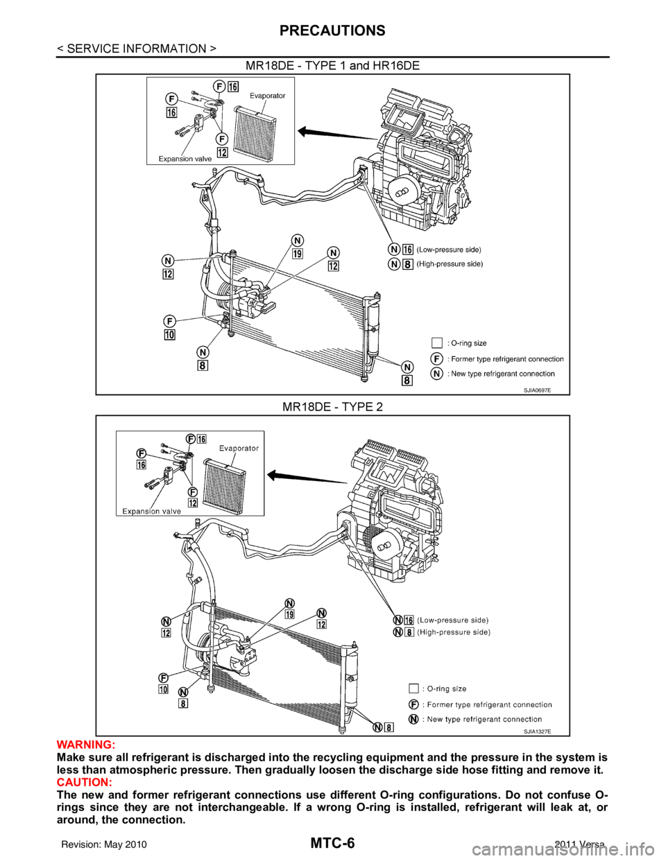
MR18DE - TYPE 1 and HR16DEMR18DE - TYPE 2
WARNING:
Make sure all refrigerant is discharged into the recycling equipment and the pressure in the system is
less than atmospheric pressure. Then gradually loo sen the discharge side hose fitting and remove it.
CAUTION:
The new and former refrigerant connections use different O-ring configurations. Do not confuse O-
rings since they are not interchangeable. If a wrong O-ring is installed, refrigerant will leak at, or
around, the connection.
SJIA0697E
SJIA1327E
Revision: May 2010 2011 Versa
Page 3352 of 3787
![NISSAN LATIO 2011 Service Repair Manual MTC-36
< SERVICE INFORMATION >
TROUBLE DIAGNOSIS
NG >> Check power supply circuit and 15A fuses [Nos. 15 and 17, located in the fuse block (J/B)].Refer to PG-4, "
Schematic".
• If fuses are OK, rein NISSAN LATIO 2011 Service Repair Manual MTC-36
< SERVICE INFORMATION >
TROUBLE DIAGNOSIS
NG >> Check power supply circuit and 15A fuses [Nos. 15 and 17, located in the fuse block (J/B)].Refer to PG-4, "
Schematic".
• If fuses are OK, rein](/img/5/57357/w960_57357-3351.png)
MTC-36
< SERVICE INFORMATION >
TROUBLE DIAGNOSIS
NG >> Check power supply circuit and 15A fuses [Nos. 15 and 17, located in the fuse block (J/B)].Refer to PG-4, "
Schematic".
• If fuses are OK, reinstall fuses and GO TO 3.
• If fuses are NG, replace fuse and check harness for short circuit. Repair or replace if necessary.
3.CHECK BLOWER MOTOR RELAY POWER SUPPLY CIRCUITS
1. Turn ignition switch OFF.
2. Disconnect blower motor relay connector.
3. Turn ignition switch ON.
4. Check voltage between blower motor relay harness connector J- 1 terminal 1, 5 and ground.
OK or NG
OK >> GO TO 4.
NG >> Repair harness or connector.
4.CHECK BLOWER MOTOR RELAY (S WITCH SIDE) CIRCUIT FOR OPEN
1. Turn ignition switch OFF.
2. Check continuity between blower motor relay harness connector J-1 (A) terminal 3 and front blower motor harness connector
M62 (B) terminal 1.
OK or NG
OK >> GO TO 5.
NG >> Repair harness or connector.
5.CHECK BLOWER MOTOR RELAY GROUND CIRCUIT
Check continuity between blower motor relay harness connector J-1
terminal 2 and ground.
OK or NG
OK >> Replace blower motor relay.
NG >> Repair harness or connector.
6.CHECK FRONT BLOWER MOTOR
Check continuity between front blower motor terminals 1 and 2.
NOTE:
Ensure that there are no foreign particles inside the A/C unit assem-
bly for a smooth rotation of the front blower motor.
OK or NG
OK >> GO TO 7.
NG >> Replace front blower motor. Refer to MTC-63, "
Removal
and Installation".
7.CHECK CIRCUIT CONTINUITY BETWEEN FRONT BLOWER MOTOR AND FRONT AIR CONTROL
1 - Ground Battery voltage should exist.
5 - Ground Battery voltage should exist.
WJIA1783E
Continuity should exist.
WJIA2263E
Continuity should exist.
WJIA2264E
1 - 2
: Continuity should exist.
WJIA2230E
Revision: May 2010 2011 Versa
Page 3355 of 3787
TROUBLE DIAGNOSISMTC-39
< SERVICE INFORMATION >
C
DE
F
G H
I
K L
M A
B
MTC
N
O P
6.CHECK MAGNET CLUTCH CIRCUIT
Perform diagnostic procedure for the magnetic clutch . Refer to "DIAGNOSTIC PROCEDURE FOR MAGNET
CLUTCH".
OK or NG
OK >> If the symptom still exists, perform a complete operational check. Refer to MTC-31, "Operational
Check". If other symptoms exist, refer to MTC-23, "How to Perform Trouble Diagnosis for Quick
and Accurate Repair".
NG >> Repair as necessary.
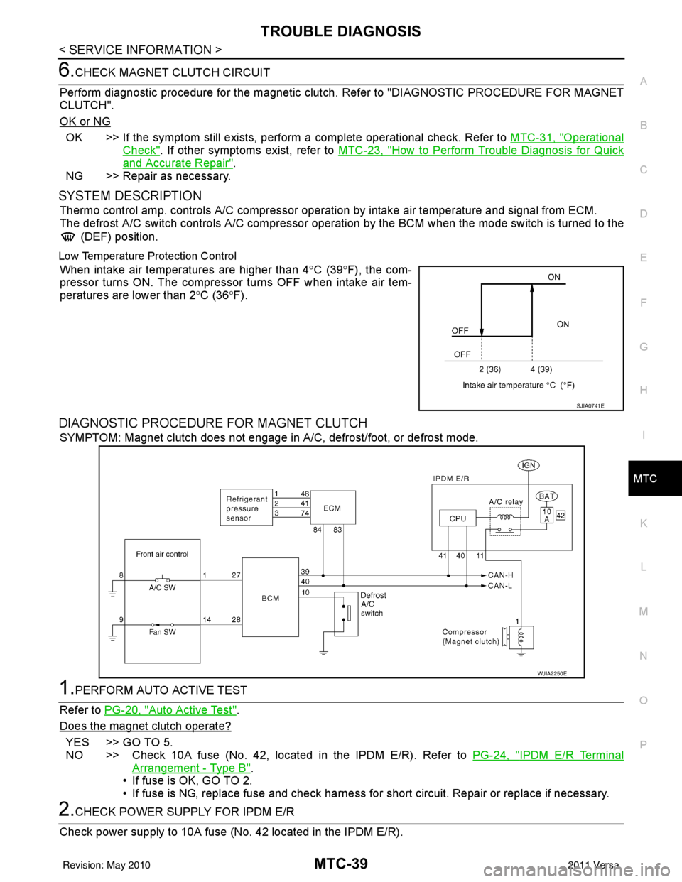
SYSTEM DESCRIPTION
Thermo control amp. controls A/C compressor operation by intake air temperature and signal from ECM.
The defrost A/C switch controls A/C compressor operati on by the BCM when the mode switch is turned to the
(DEF) position.
Low Temperature Protection Control
When intake air temperatures are higher than 4 °C (39° F), the com-
pressor turns ON. The compressor turns OFF when intake air tem-
peratures are lower than 2 °C (36° F).
DIAGNOSTIC PROCEDURE FOR MAGNET CLUTCH
SYMPTOM: Magnet clutch does not engage in A/C, defrost/foot, or defrost mode.
1.PERFORM AUTO ACTIVE TEST
Refer to PG-20, "
Auto Active Test".
Does the magnet clutch operate?
YES >> GO TO 5.
NO >> Check 10A fuse (No. 42, located in the IPDM E/R). Refer to PG-24, "
IPDM E/R Terminal
Arrangement - Type B".
• If fuse is OK, GO TO 2.
• If fuse is NG, replace fuse and check harness for short circuit. Repair or replace if necessary.
2.CHECK POWER SUPPLY FOR IPDM E/R
Check power supply to 10A fuse (No. 42 located in the IPDM E/R).
SJIA0741E
WJIA2250E
Revision: May 2010 2011 Versa
Page 3360 of 3787
MTC-44
< SERVICE INFORMATION >
TROUBLE DIAGNOSIS
OK or NG
OK >> • GO TO 18 (with CVT).• GO TO 19 (without CVT).
NG >> GO TO 21.
18.CHECK THERMO CONTROL AMP. GROUND CIRCUIT
1. Turn ignition switch OFF.
2. Check continuity between thermo control amp. harness connec- tor M42 terminal 2 and ground.
OK or NG
OK >> Repair thermo control amp. jumper as necessary.
NG >> Repair harness or connector.
19.CHECK POWER SUPPLY FOR THERMO CONTROL AMP.
Check voltage between thermo control amp. harness connector M42
terminal 1 and ground.
OK or NG
OK >> GO TO 20.
NG >> Check power supply circuit and 10A fuse [No. 16, located in the fuse block (JB)]. Refer to PG-73
.
• If fuse is OK, check harness for open circuit. Repair or
replace if necessary.
• If fuse is NG, replace fuse and check harness for short circuit. Repair or replace if necessary.
20.CHECK THERMO CONTROL AMP. GROUND CIRCUIT
1. Turn ignition switch OFF.
2. Check continuity between thermo control amp. harness connec- tor M42 terminal 2 and ground.
OK or NG
OK >> Replace thermo control amp. Refer to MTC-58,
"Removal and Installation".
NG >> Repair harness or connector.
21.CHECK CIRCUIT CONTINUITY BETWEEN THERMO CONTROL AMP. AND BCM
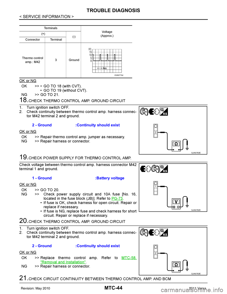
Te r m i n a l s
Vo l ta g e
(Approx.)
(+)
(-)
Connector Terminal
Thermo control amp.: M42 3Ground
ZJIA0719J
2 - Ground
:Continuity should exist
SJIA0763E
1 - Ground :Battery voltage
SJIA0762E
2 - Ground:Continuity should exist
SJIA0763E
Revision: May 2010 2011 Versa
Page 3421 of 3787

PG-1
ELECTRICAL
C
DE
F
G H
I
J
L
M
SECTION PG
A
B
PG
N
O P
CONTENTS
POWER SUPPLY, GROUND & CIRCUIT ELEMENTS
SERVICE INFORMATION .. ..........................2
PRECAUTIONS .............................................. .....2
Precaution for Supplemental Restraint System
(SRS) "AIR BAG" and "SEAT BELT PRE-TEN-
SIONER" ............................................................. ......
2
Precaution Necessary for Steering Wheel Rota-
tion After Battery Disconnect ............................... ......
2
POWER SUPPLY ROUTING CIRCUIT ...............4
Schematic ........................................................... ......4
Wiring Diagram - POWER - ......................................6
Fuse ........................................................................16
Fusible Link .............................................................16
Circuit Breaker (Built Into BCM) ..............................16
Circuit Breaker ........................................................16
IPDM E/R (INTELLIGENT POWER DISTRI-
BUTION MODULE ENGINE ROOM) .................
17
System Description ............................................. ....17
CAN Communication System Description ...............18
Function of Detecting Ignition Relay Malfunction ....18
CONSULT-III Function (IPDM E/R) ..................... ....18
Auto Active Test ......................................................20
IPDM E/R Terminal Arrangement - Type A .............23
IPDM E/R Terminal Arrangement - Type B .............24
Terminal and Reference Value for IPDM E/R .........25
IPDM E/R Power/Ground Circuit Inspection ...........27
Inspection with CONSULT-III (Self-Diagnosis) .......28
Removal and Installation of IPDM E/R ................ ....28
GROUND CIRCUIT ...........................................30
Ground Distribution .............................................. ....30
HARNESS .........................................................39
Harness Layout ................................................... ....39
Wiring Diagram Codes (Cell Codes) .......................58
ELECTRICAL UNITS LOCATION ....................61
Electrical Units Location ..........................................61
HARNESS CONNECTOR .................................65
Description ...............................................................65
ELECTRICAL UNITS ........................................68
Terminal Arrangement .............................................68
STANDARDIZED RELAY .................................69
Description ...............................................................69
SUPER MULTIPLE JUNCTION (SMJ) .............71
Terminal Arrangement .............................................71
FUSE BLOCK-JUNCTION BOX (J/B) ..............73
Terminal Arrangement .............................................73
FUSE AND FUSIBLE LINK BOX ......................74
Terminal Arrangement .............................................74
Revision: May 2010 2011 Versa
Page 3436 of 3787
PG-16
< SERVICE INFORMATION >
POWER SUPPLY ROUTING CIRCUIT
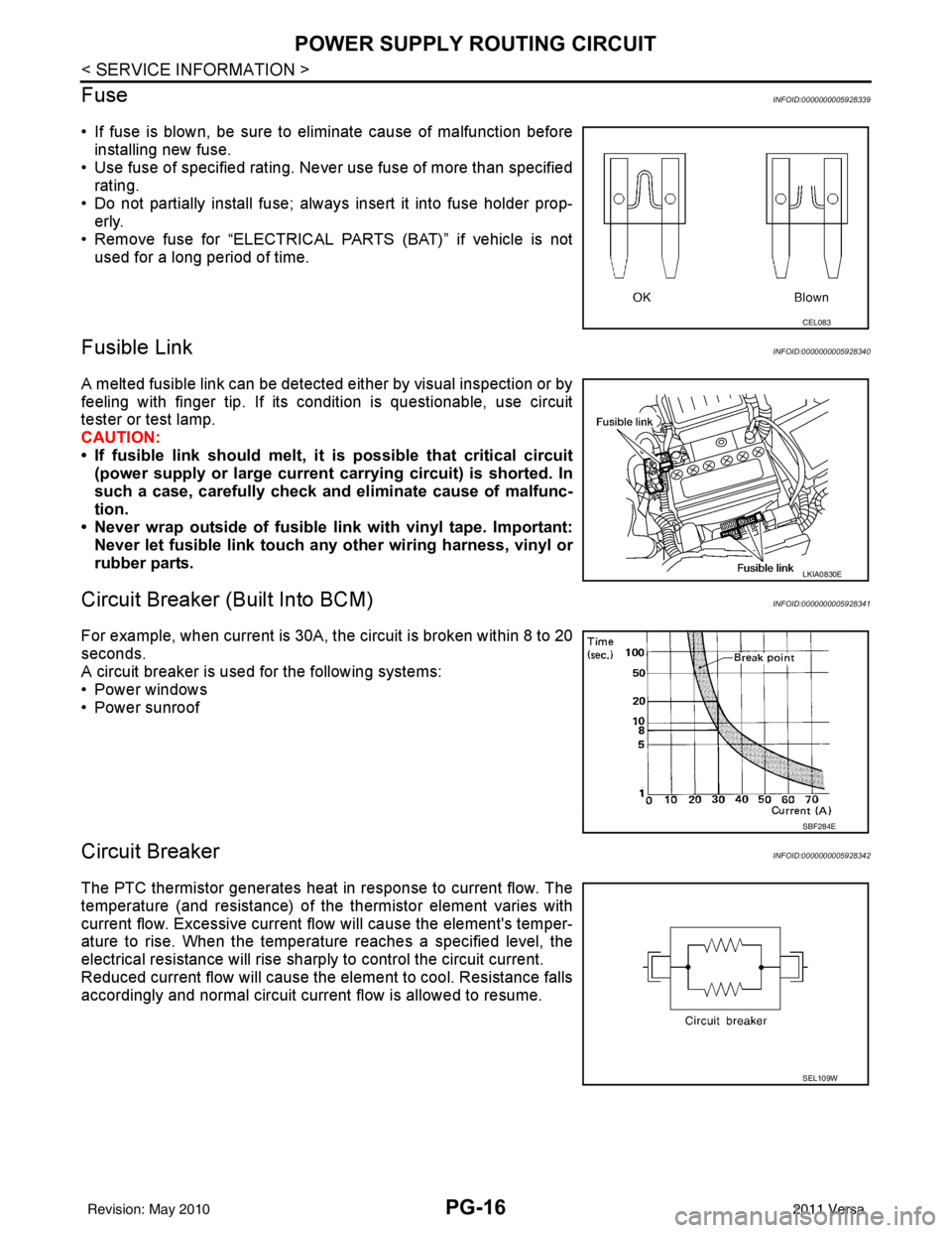
Fuse
INFOID:0000000005928339
• If fuse is blown, be sure to eliminate cause of malfunction before installing new fuse.
• Use fuse of specified rating. Never use fuse of more than specified
rating.
• Do not partially install fuse; always insert it into fuse holder prop- erly.
• Remove fuse for “ELECTRICAL PARTS (BAT)” if vehicle is not used for a long period of time.
Fusible LinkINFOID:0000000005928340
A melted fusible link can be detected either by visual inspection or by
feeling with finger tip. If its condition is questionable, use circuit
tester or test lamp.
CAUTION:
• If fusible link should melt, it is possible that critical circuit
(power supply or large current carrying circuit) is shorted. In
such a case, carefully check and eliminate cause of malfunc-
tion.
• Never wrap outside of fusible link with vinyl tape. Important:
Never let fusible link touch an y other wiring harness, vinyl or
rubber parts.
Circuit Breaker (Built Into BCM)INFOID:0000000005928341
For example, when current is 30A, t he circuit is broken within 8 to 20
seconds.
A circuit breaker is used for the following systems:
• Power windows
• Power sunroof
Circuit BreakerINFOID:0000000005928342
The PTC thermistor generates heat in response to current flow. The
temperature (and resistance) of the thermistor element varies with
current flow. Excessive current flow will cause the element's temper-
ature to rise. When the temperature reaches a specified level, the
electrical resistance will rise sharply to control the circuit current.
Reduced current flow will cause the element to cool. Resistance falls
accordingly and normal circuit current flow is allowed to resume.
CEL083
LKIA0830E
SBF284E
SEL109W
Revision: May 2010 2011 Versa