fuse NISSAN LATIO 2011 Service Repair Manual
[x] Cancel search | Manufacturer: NISSAN, Model Year: 2011, Model line: LATIO, Model: NISSAN LATIO 2011Pages: 3787, PDF Size: 78.35 MB
Page 3697 of 3787
![NISSAN LATIO 2011 Service Repair Manual STC-10
< DTC/CIRCUIT DIAGNOSIS >[EPS]
C1601 BATTERY POWER SUPPLY
Is the inspection result normal?
YES >> GO TO 3.
NO >> Check the following. If any items are damaged, repair or replace damaged parts.
NISSAN LATIO 2011 Service Repair Manual STC-10
< DTC/CIRCUIT DIAGNOSIS >[EPS]
C1601 BATTERY POWER SUPPLY
Is the inspection result normal?
YES >> GO TO 3.
NO >> Check the following. If any items are damaged, repair or replace damaged parts.](/img/5/57357/w960_57357-3696.png)
STC-10
< DTC/CIRCUIT DIAGNOSIS >[EPS]
C1601 BATTERY POWER SUPPLY
Is the inspection result normal?
YES >> GO TO 3.
NO >> Check the following. If any items are damaged, repair or replace damaged parts.
• 10A fuse (#2) open
- Harness for short between 10A fuse (#2) and pow er steering control unit harness connector No.
10 terminal.
• 60A fusible link (M) open
- Harness for short between 60A fusible link (M) and power steering control unit harness connec-
tor No. 10 terminal.
• Harness for open between ignition switch and power steering control unit harness connector No. 17 terminal.
• Harness for open between battery and power steering control unit harness connector No. 17 ter-
minal.
• Battery or ignition switch.
3.CHECK BATTERY VOLTAGE SIGNAL (1)
With CONSULT-III
1. Connect EPS control unit harness connector.
2. Start the engine. CAUTION:
Stop the vehicle.
3. Select “EPS”, “DATA MONITOR” and “MOTOR VO LT”, and perform the battery voltage inspection.
Is the inspection result normal?
YES >> GO TO 4.
NO >> Replace EPS control unit. Refer to PS-10, "
Removal and Installation".
4.CHECK MOTOR VOLTAGE SIGNAL (2)
With CONSULT-III
Select “MOTOR VOLT” in “DATA MONITOR” of the EPS control unit. Check motor voltage with the steering
wheel fully turned leftward or rightward.
Is the value in
“DATA MONITOR”“between 9 V and 17.5 V”?
YES >> Check pin terminal and connection of each harness connector for damage or loose connection.
NO >> Check battery power supply and ignition power supply. Refer to STC-22, "
Wiring Diagram - ELEC-
TRONICALLY CONTROLLED POWER STEERING SYSTEM -".
EPS control unit
—Volt a ge
Connector Terminal
M53 10
Ground Battery voltage
M54 17
Monitor item ConditionDisplay value
MOTOR VOLT Engine runningBattery voltage
Revision: May 2010 2011 Versa
Page 3736 of 3787

WT-18
< SERVICE INFORMATION >
TROUBLE DIAGNOSES
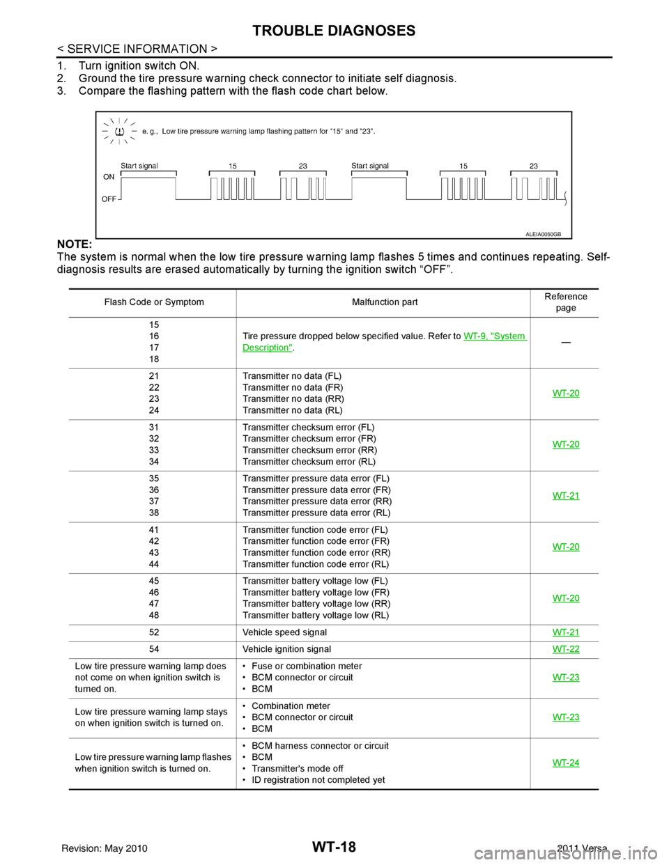
1. Turn ignition switch ON.
2. Ground the tire pressure warning check connector to initiate self diagnosis.
3. Compare the flashing pattern with the flash code chart below.
NOTE:
The system is normal when the low tire pressure warning lamp flashes 5 times and continues repeating. Self-
diagnosis results are erased automatically by turning the ignition switch “OFF”.
Flash Code or Symptom Malfunction partReference
page
15
16
17
18 Tire pressure dropped below specified value. Refer to
WT-9, "
System
Description". —
21
22
23
24 Transmitter no data (FL)
Transmitter no data (FR)
Transmitter no data (RR)
Transmitter no data (RL)
WT-20
31
32
33
34Transmitter chec
ksum error (FL)
Transmitter chec ksum error (FR)
Transmitter chec ksum error (RR)
Transmitter chec ksum error (RL) WT-20
35
36
37
38Transmitter pressure
data error (FL)
Transmitter pressure data error (FR)
Transmitter pressure data error (RR)
Transmitter pressure data error (RL) WT-21
41
42
43
44Transmitter function
code error (FL)
Transmitter function code error (FR)
Transmitter function code error (RR)
Transmitter function code error (RL) WT-20
45
46
47
48Transmitter battery voltage low (FL)
Transmitter battery voltage low (FR)
Transmitter battery voltage low (RR)
Transmitter battery voltage low (RL)
WT-20
52
Vehicle speed signal WT-21
54Vehicle ignition signal WT-22
Low tire pressure warning lamp does
not come on when ignition switch is
turned on.• Fuse or combination meter
• BCM connector or circuit
•BCM
WT-23
Low tire pressure
warning lamp stays
on when ignition switch is turned on. • Combination meter
• BCM connector or circuit
•BCM
WT-23
Low tire pressure wa
rning lamp flashes
when ignition switch is turned on. • BCM harness connector or circuit
•BCM
• Transmitter's mode off
• ID registration not completed yet
WT-24
ALEIA0050GB
Revision: May 2010
2011 Versa
Page 3751 of 3787

FRONT WIPER AND WASHER SYSTEMWW-5
< SERVICE INFORMATION >
C
DE
F
G H
I
J
L
M A
B
WW
N
O P
FRONT WIPER AND WASHER SYSTEM
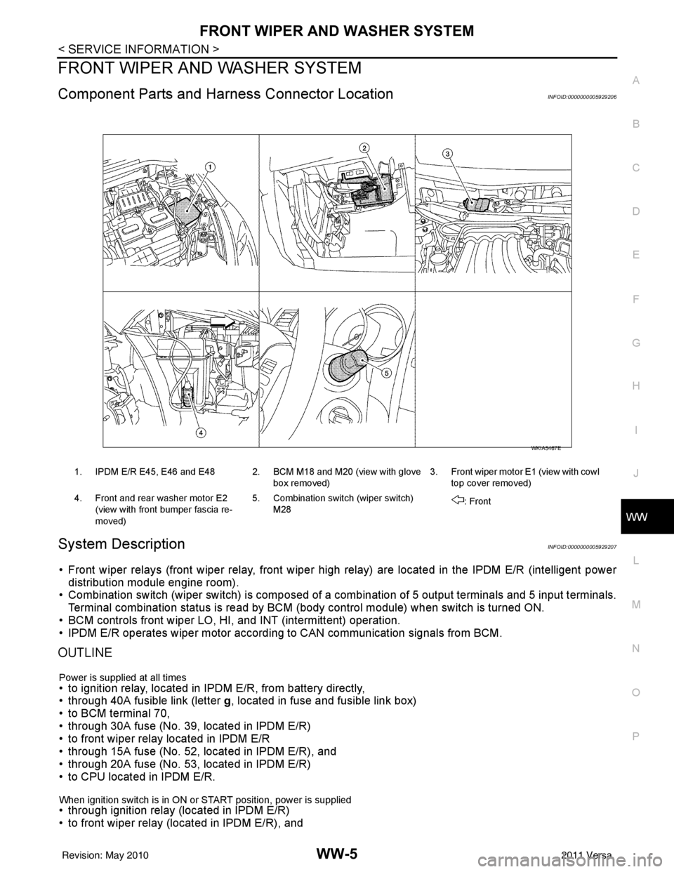
Component Parts and Har ness Connector LocationINFOID:0000000005929206
System DescriptionINFOID:0000000005929207
• Front wiper relays (front wiper relay, front wiper high relay) are located in the IPDM E/R (intelligent power
distribution module engine room).
• Combination switch (wiper switch) is composed of a combination of 5 output terminals and 5 input terminals.
Terminal combination status is read by BCM (body control module) when switch is turned ON.
• BCM controls front wiper LO, HI, and INT (intermittent) operation.
• IPDM E/R operates wiper motor accordi ng to CAN communication signals from BCM.
OUTLINE
Power is supplied at all times• to ignition relay, located in IPDM E/R, from battery directly,
• through 40A fusible link (letter g, located in fuse and fusible link box)
• to BCM terminal 70,
• through 30A fuse (No. 39, located in IPDM E/R)
• to front wiper relay located in IPDM E/R
• through 15A fuse (No. 52, located in IPDM E/R), and
• through 20A fuse (No. 53, located in IPDM E/R)
• to CPU located in IPDM E/R.
When ignition switch is in ON or START position, power is supplied • through ignition relay (located in IPDM E/R)
• to front wiper relay (located in IPDM E/R), and
1. IPDM E/R E45, E46 and E48 2. BCM M18 and M20 (view with glove
box removed)3. Front wiper motor E1
(view with cowl
top cover removed)
4. Front and rear washer motor E2 (view with front bumper fascia re-
moved) 5. Combination switch (wiper switch)
M28 : Front
WKIA5467E
Revision: May 2010
2011 Versa
Page 3752 of 3787

WW-6
< SERVICE INFORMATION >
FRONT WIPER AND WASHER SYSTEM
• to front wiper high relay (located in IPDM E/R), and
• to CPU (located in IPDM E/R),
• through 10A fuse [No. 6, located in fuse block (J/B)]
• to BCM terminal 38,
• through 15A fuse [No. 4, located in fuse block (J/B)]
• to combination switch (wiper switch) terminal 14.
Ground is supplied
• to IPDM E/R terminals 39 and 59, and
• to front wiper motor terminal 2
• through grounds E15 and E24
• to BCM terminal 67, and
• to combination switch (wiper switch) terminal 12
• through grounds M57 and M61.
LOW SPEED WIPER OPERATION
When the front combination switch (wiper switch) is in LO position, the BCM detects the low speed wiper ON
signal by means of the BCM combination switch (wiper switch) reading function.
The BCM sends a front wiper request signal (LO) through the CAN communication line
• from BCM terminals 39 and 40
• to IPDM E/R terminals 40 and 41.
When the IPDM E/R receives front wiper request signal (LO) , it turns ON front wiper relay, located in IPDM E/
R, power is supplied
• through IPDM E/R terminal 33 and front wiper high relay and front wiper relay
• to front wiper motor terminal 3.
Ground is supplied
• to front wiper motor terminal 2
• through grounds E15 and E24.
With power and ground is supplied, front wiper motor operates at low speed.
HIGH SPEED WIPER OPERATION
When the front combination switch (wiper switch) is in HI position, the BCM detects a high speed wiper ON
signal by means of the BCM combination switch (wiper switch) reading function.
The BCM sends a front wiper request signal (HI) through the CAN communication line
• from BCM terminals 39 and 40
• to IPDM E/R terminals 40 and 41.
When the IPDM E/R receives front wiper request signal (HI), it turns ON front wiper relay and front wiper high
relay, located in IPDM E/R, power is supplied
• through IPDM E/R terminal 32
• to front wiper motor terminal 5.
Ground is supplied
• to front wiper motor terminal 2
• through grounds E15 and E24.
With power and ground is supplied, front wiper motor operates at high speed.
INTERMITTENT OPERATION
Wiper intermittent operation delay interval is determined from the intermittent wiper dial position inputs. During
each intermittent operation delay interval, the BCM s ends a front wiper request signal to the IPDM E/R to
operate the wipers.
When the ignition switch is in the ON or START positi on, and the front combination switch (wiper switch) is
turned to the intermittent position, the BCM detects a fr ont wiper (intermittent) ON signal by means of the BCM
combination switch (wiper switch) reading function.
BCM then sends front wiper (intermittent) request signal through the CAN communication lines
• from BCM terminals 39 and 40
• to IPDM E/R terminals 40 and 41.
When BCM determines that combination switch (wiper swit ch) status is front wiper intermittent ON, it performs
the following operations.
• BCM detects ON/OFF status of intermittent wiper dial position
• BCM calculates operation interval from wiper dial position.
• BCM sends a front wiper request signal (INT) to IPDM E/R at calculated operation interval.
When IPDM E/R receives the front wiper request signal (INT), it supplies ground to energize the front wiper
relay. It then sends auto-stop signal to the BCM and conducts intermittent front wiper motor operation.
Revision: May 2010 2011 Versa
Page 3773 of 3787

REAR WIPER AND WASHER SYSTEMWW-27
< SERVICE INFORMATION >
C
DE
F
G H
I
J
L
M A
B
WW
N
O P
REAR WIPER AND WASHER SYSTEM
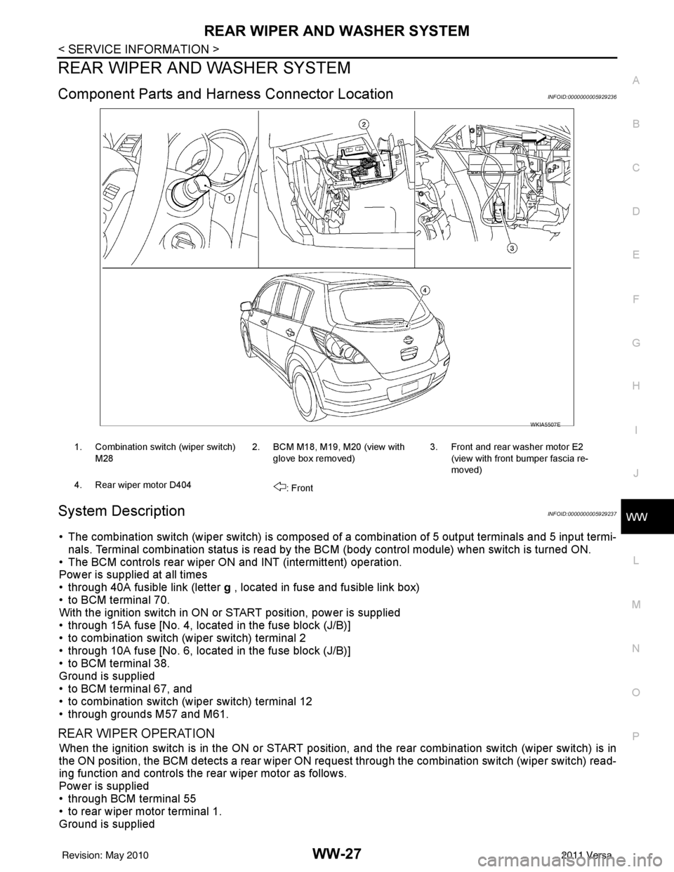
Component Parts and Har ness Connector LocationINFOID:0000000005929236
System DescriptionINFOID:0000000005929237
• The combination switch (wiper switch) is composed of a combination of 5 output terminals and 5 input termi-
nals. Terminal combination status is read by the BCM (body control module) when switch is turned ON.
• The BCM controls rear wiper ON and INT (intermittent) operation.
Power is supplied at all times
• through 40A fusible link (letter g , located in fuse and fusible link box)
• to BCM terminal 70.
With the ignition switch in ON or START position, power is supplied
• through 15A fuse [No. 4, located in the fuse block (J/B)]
• to combination switch (wiper switch) terminal 2
• through 10A fuse [No. 6, located in the fuse block (J/B)]
• to BCM terminal 38.
Ground is supplied
• to BCM terminal 67, and
• to combination switch (wiper switch) terminal 12
• through grounds M57 and M61.
REAR WIPER OPERATION
When the ignition switch is in the ON or START position, and the rear combination switch (wiper switch) is in
the ON position, the BCM detects a rear wiper ON r equest through the combination switch (wiper switch) read-
ing function and controls the rear wiper motor as follows.
Power is supplied
• through BCM terminal 55
• to rear wiper motor terminal 1.
Ground is supplied
WKIA5507E
1. Combination switch (wiper switch)
M28 2. BCM M18, M19, M20 (view with
glove box removed) 3. Front and rear washer motor E2
(view with front bumper fascia re-
moved)
4. Rear wiper motor D404 : Front
Revision: May 2010 2011 Versa
Page 3774 of 3787

WW-28
< SERVICE INFORMATION >
REAR WIPER AND WASHER SYSTEM
• to rear wiper motor terminal 3
• through grounds B117, B132 and D402.
With power and ground supplied, the rear wiper motor operates.
INTERMITTENT OPERATION
The rear wiper motor operates the wiper arm at low speed approximately every 7 seconds.
When the combination switch (wiper switch) is in the r ear wiper INT position, the BCM detects a rear wiper INT
request through the combination switch (wiper switch) reading function.
When BCM operates rear wiper motor, power is supplied
• through BCM terminal 55
• to rear wiper motor terminal 1.
Ground is supplied
• to rear wiper motor terminal 3
• through grounds B117, B132 and D402.
With power and ground supplied, the rear wiper operates in intermittent mode.
AUTO STOP OPERATION
When the rear wiper arm is not located at the base of the rear window, and the rear combination switch (wiper
switch) is turned OFF, the rear wiper motor will continue to operate until the rear wiper arm is at the base of the
rear window. When the rear wiper arm reaches the bas e, rear wiper motor terminals 2 and 1 are connected.
Ground is supplied
• to BCM terminal 44
• through rear wiper motor terminal 2, and
• through rear wiper motor terminal 3, and
• through grounds B117, B132 and D402.
REAR WASHER OPERATION
When the ignition switch is in the ON or START positi on, and the front and rear washer switches are OFF, the
front and rear washer motor is supplied power
• through 15A fuse [No. 4, located in the fuse block (J/B)]
• to combination switch (wiper switch) terminal 14
• through combination switch (wiper switch) terminal 11
• to front and rear washer motor terminal 2.
When the rear combination switch (wiper switch) is in rear washer position, the BCM detects a rear washer
signal by BCM combination switch (wiper switch) readi ng function. Combination switch (wiper switch) ground
is supplied
• to front and rear washer motor terminal 1
• through combination switch (wiper switch) terminal 13, and
• through combination switch (wiper switch) terminal 12
• through grounds M57 and M61.
With ground supplied, the front and rear washer motor is operated in the rear direction.
When the BCM detects that the rear washer motor has operated for 0.4 seconds or longer, BCM operates the
rear wiper motor.
When the BCM detects that the rear washer switch is in OFF, the rear wiper motor cycles approximately 3
times and then stops.
If the rear washer is operated with the rear combinati on switch (wiper switch) in the INT position, normal rear
wiper operation will take over. Once the rear washer switch is released the rear wiper will return to INT opera-
tion.
BCM Combination Switch (Wiper Switch) Reading Function
Refer to BCS-4, "System Description" .
Revision: May 2010 2011 Versa
Page 3784 of 3787

WW-38
< SERVICE INFORMATION >
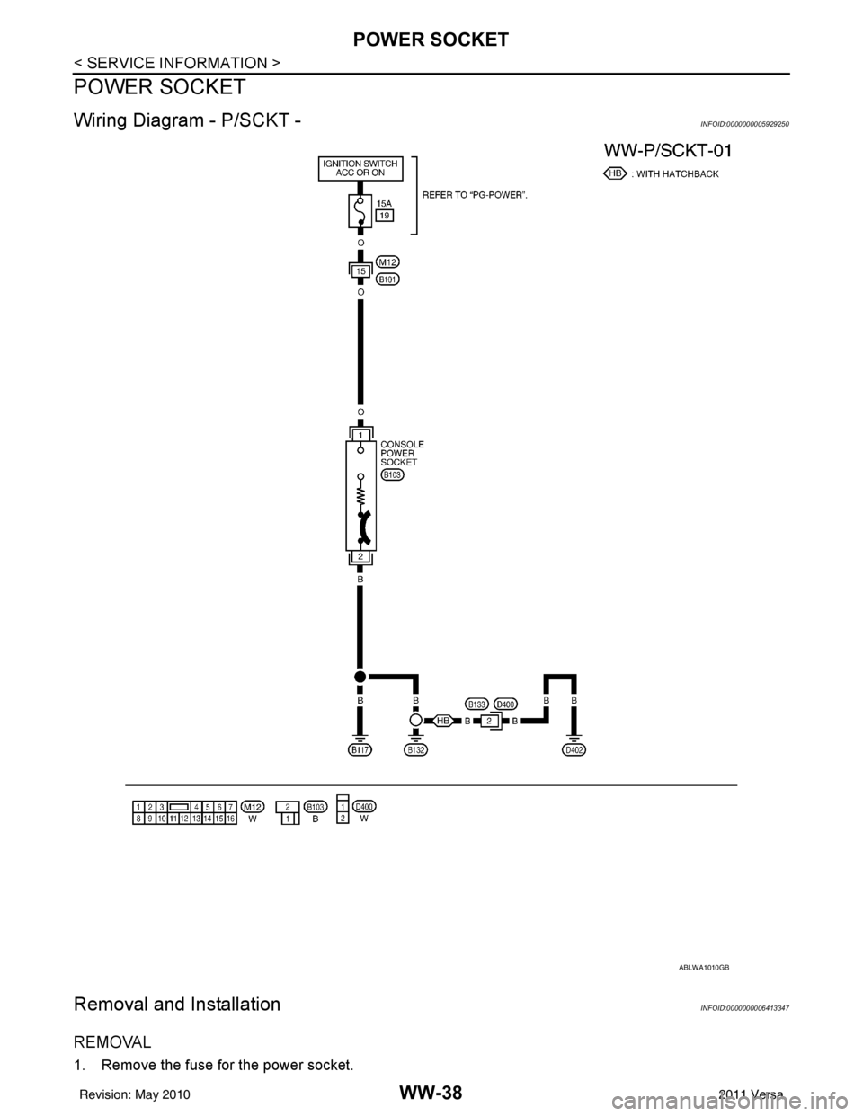
POWER SOCKET
POWER SOCKET
Wiring Diagram - P/SCKT -INFOID:0000000005929250
Removal and InstallationINFOID:0000000006413347
REMOVAL
1. Remove the fuse for the power socket.
ABLWA1010GB
Revision: May 20102011 Versa