fog light NISSAN LATIO 2011 Service User Guide
[x] Cancel search | Manufacturer: NISSAN, Model Year: 2011, Model line: LATIO, Model: NISSAN LATIO 2011Pages: 3787, PDF Size: 78.35 MB
Page 736 of 3787
BL-226
< SERVICE INFORMATION >
VEHICLE SECURITY (THEFT WARNING) SYSTEM
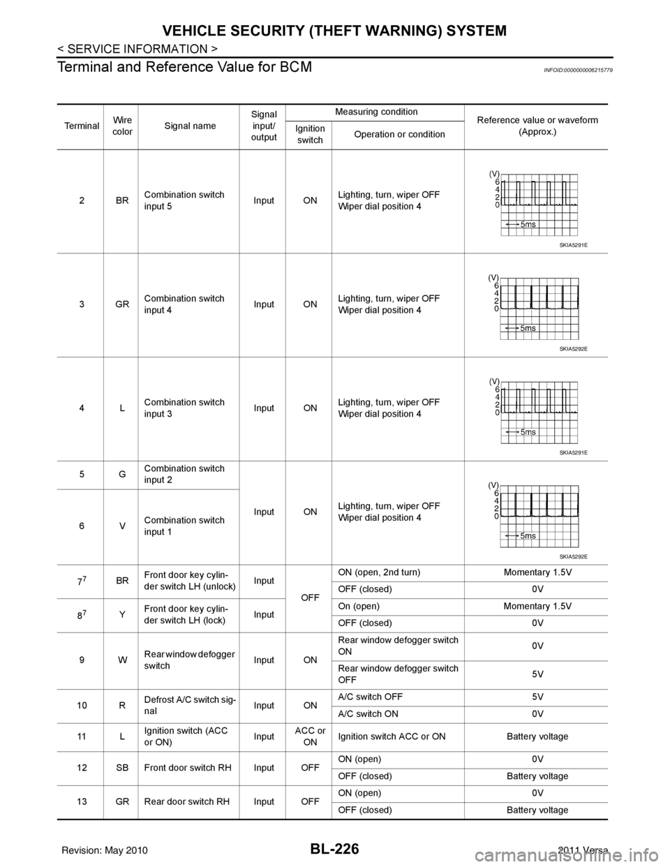
Terminal and Reference Value for BCM
INFOID:0000000006215779
Te r m i n a l Wire
color Signal name Signal
input/
output Measuring condition
Reference value or waveform
(Approx.)
Ignition
switch Operation or condition
2BR Combination switch
input 5
Input ONLighting, turn, wiper OFF
Wiper dial position 4
3GR Combination switch
input 4 Input ONLighting, turn, wiper OFF
Wiper dial position 4
4L Combination switch
input 3
Input ONLighting, turn, wiper OFF
Wiper dial position 4
5G Combination switch
input 2
Input ONLighting, turn, wiper OFF
Wiper dial position 4
6V Combination switch
input 1
7
7BR Front door key cylin-
der switch LH (unlock) Input
OFFON (open, 2nd turn)
Momentary 1.5V
OFF (closed) 0V
8
7Y Front door key cylin-
der switch LH (lock) InputOn (open)
Momentary 1.5V
OFF (closed) 0V
9W Rear window defogger
switch Input ONRear window defogger switch
ON
0V
Rear window defogger switch
OFF 5V
10 R Defrost A/C switch sig-
nal
Input ONA/C switch OFF
5V
A/C switch ON 0V
11 L Ignition switch (ACC
or ON) InputACC or
ON Ignition switch ACC or ON
Battery voltage
12 SB Front door switch RH Input OFF ON (open)
0V
OFF (closed) Battery voltage
13 GR Rear door switch RH Input OFF ON (open)
0V
OFF (closed) Battery voltage
SKIA5291E
SKIA5292E
SKIA5291E
SKIA5292E
Revision: May 2010 2011 Versa
Page 760 of 3787
BL-250
< SERVICE INFORMATION >
NATS (NISSAN ANTI-THEFT SYSTEM)
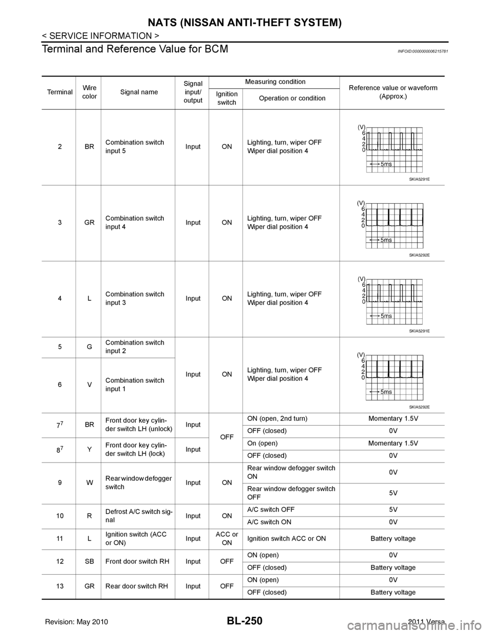
Terminal and Reference Value for BCM
INFOID:0000000006215781
Te r m i n a l Wire
color Signal name Signal
input/
output Measuring condition
Reference value or waveform
(Approx.)
Ignition
switch Operation or condition
2BR Combination switch
input 5
Input ONLighting, turn, wiper OFF
Wiper dial position 4
3GR Combination switch
input 4 Input ONLighting, turn, wiper OFF
Wiper dial position 4
4L Combination switch
input 3
Input ONLighting, turn, wiper OFF
Wiper dial position 4
5G Combination switch
input 2
Input ONLighting, turn, wiper OFF
Wiper dial position 4
6V Combination switch
input 1
7
7BR Front door key cylin-
der switch LH (unlock) Input
OFFON (open, 2nd turn)
Momentary 1.5V
OFF (closed) 0V
8
7Y Front door key cylin-
der switch LH (lock) InputOn (open)
Momentary 1.5V
OFF (closed) 0V
9W Rear window defogger
switch Input ONRear window defogger switch
ON
0V
Rear window defogger switch
OFF 5V
10 R Defrost A/C switch sig-
nal
Input ONA/C switch OFF
5V
A/C switch ON 0V
11 L Ignition switch (ACC
or ON) InputACC or
ON Ignition switch ACC or ON
Battery voltage
12 SB Front door switch RH Input OFF ON (open)
0V
OFF (closed) Battery voltage
13 GR Rear door switch RH Input OFF ON (open)
0V
OFF (closed) Battery voltage
SKIA5291E
SKIA5292E
SKIA5291E
SKIA5292E
Revision: May 2010 2011 Versa
Page 1320 of 3787
![NISSAN LATIO 2011 Service User Guide EC-26
< BASIC INSPECTION >[HR16DE]
INSPECTION AND ADJUSTMENT
• Each time electric throttle control actuator or ECM is replaced.
• Idle speed or ignition timing is out of specification.
IDLE AIR VO](/img/5/57357/w960_57357-1319.png "NISSAN LATIO 2011 Service User Guide EC-26
< BASIC INSPECTION >[HR16DE]
INSPECTION AND ADJUSTMENT
• Each time electric throttle control actuator or ECM is replaced.
• Idle speed or ignition timing is out of specification.
IDLE AIR VO")
EC-26
< BASIC INSPECTION >[HR16DE]
INSPECTION AND ADJUSTMENT
• Each time electric throttle control actuator or ECM is replaced.
• Idle speed or ignition timing is out of specification.
IDLE AIR VOLUME LEARNING
: Special Repair RequirementINFOID:0000000005929760
1.PRECONDITIONING
Make sure that all of the following conditions are satisfied.
Learning will be cancelled if any of the follo wing conditions are missed for even a moment.
• Battery voltage: More than 12.9 V (At idle)
• Engine coolant temperature: 70 - 100 °C (158 - 212° F)
• Selector lever: P or N (A/T), Neutral (M/T)
• Electric load switch: OFF (Air conditioner, headlamp, rear window defogger)
On vehicles equipped with daytime light systems, if the parking brake is applied before the engine is
started the headlamp will not be illuminated.
• Steering wheel: Neutral (Straight-ahead position)
• Vehicle speed: Stopped
• Transmission: Warmed-up
- A/T models
• With CONSULT-III: Drive vehicle until “FLUID TEMP SE” in “DATA MONITOR” mode of “TRANSMISSION”
system indicates less than 0.9 V.
• Without CONSULT-III: Drive vehicle for 10 minutes.
- M/T models
• Drive vehicle for 10 minutes.
Do you have CONSULT-III?
YES >> GO TO 2.
NO >> GO TO 3.
2.IDLE AIR VOLUME LEARNING
With CONSULT-III
1. Perform Accelerator Pedal Released Position Learning. Refer to EC-25, "
ACCELERATOR PEDAL
RELEASED POSITION LEARNING : Special Repair Requirement".
2. Perform Throttle Valve Closed Position Learning. Refer to EC-25, "
THROTTLE VALVE CLOSED POSI-
TION LEARNING : Special Repair Requirement".
3. Start engine and warm it up to normal operating temperature.
4. Select “IDLE AIR VOL LEARN” in “WORK SUPPORT” mode.
5. Touch “START” and wait 20 seconds.
Is
“CMPLT” displayed on CONSULT-III screen?
YES >> GO TO 4.
NO >> GO TO 5.
3.IDLE AIR VOLUME LEARNING
Without CONSULT-III
NOTE:
• It is better to count the ti me accurately with a clock.
• It is impossible to switch the di agnostic mode when an accelerator pedal position sensor circuit has
a malfunction.
1. Perform Accelerator Pedal Released Position Learning. Refer to EC-25, "
ACCELERATOR PEDAL
RELEASED POSITION LEARNING : Special Repair Requirement".
2. Perform Throttle Valve Closed Position Learning. Refer to EC-25, "
THROTTLE VALVE CLOSED POSI-
TION LEARNING : Special Repair Requirement".
3. Start engine and warm it up to normal operating temperature.
4. Turn ignition switch OFF and wait at least 10 seconds.
5. Confirm that accelerator pedal is fully releas ed, turn ignition switch ON and wait 3 seconds.
6. Repeat the following procedure quickly five times within 5 seconds.
- Fully depress the accelerator pedal.
- Fully release the accelerator pedal.
7. Wait 7 seconds, fully depress the accelerator pedal and keep it for approx. 20 seconds until the MIL stops
blinking and turned ON.
8. Fully release the accelerator pedal within 3 seconds after the MIL turned ON.
Revision: May 2010 2011 Versa
Page 1403 of 3787
![NISSAN LATIO 2011 Service User Guide DIAGNOSIS SYSTEM (ECM)EC-109
< FUNCTION DIAGNOSIS > [HR16DE]
C
D
E
F
G H
I
J
K L
M A
EC
NP
OA/F ALPHA-B1
%• The mean value of the air-fuel ratio feedback correc-
tion factor per cycle is indicated.](/img/5/57357/w960_57357-1402.png "NISSAN LATIO 2011 Service User Guide DIAGNOSIS SYSTEM (ECM)EC-109
< FUNCTION DIAGNOSIS > [HR16DE]
C
D
E
F
G H
I
J
K L
M A
EC
NP
OA/F ALPHA-B1
%• The mean value of the air-fuel ratio feedback correc-
tion factor per cycle is indicated.")
DIAGNOSIS SYSTEM (ECM)EC-109
< FUNCTION DIAGNOSIS > [HR16DE]
C
D
E
F
G H
I
J
K L
M A
EC
NP
OA/F ALPHA-B1
%• The mean value of the air-fuel ratio feedback correc-
tion factor per cycle is indicated. • When the engine is stopped, a certain
value is indicated.
• This data also includes the data for the air-fuel ratio learning control.
• When engine is running specification
range is indicated in “SPEC”.
COOLAN TEMP/S °C or °F • The engine coolant temperature (determined by the
signal voltage of the engine coolant temperature sen-
sor) is displayed. • When the engine coolant temperature
sensor is open or short-circuited,
ECM enters fail-safe mode. The en-
gine coolant temperature determined
by the ECM is displayed.
A/F SEN1 (B1) V• The A/F signal computed from the input signal of the
air fuel ratio (A/F) se nsor 1 is displayed.
HO2S2 (B1) V• The signal voltage of the heated oxygen sensor 2 is
displayed.
HO2S2 MNTR(B1) RICH/
LEAN • Display of heated oxygen sensor 2 signal:
RICH: means the amount of oxygen after three way
catalyst is relatively small.
LEAN: means the amount of oxygen after three way
catalyst is relatively large. • When the engine is stopped, a certain
value is indicated.
VHCL SPEED SE km/h or
mph • The vehicle speed computed from the vehicle speed
signal sent from combination meter is displayed.
BATTERY VOLT V • The power supply voltage of ECM is displayed.
ACCEL SEN 1 V• The accelerator pedal position sensor signal voltage is
displayed. • ACCEL SEN 2 signal is converted by
ECM internally. Thus, it differs from
ECM terminal voltage signal.
ACCEL SEN 2
TP SEN 1-B1
V• The throttle position sensor signal voltage is dis-
played. • TP SEN 2-B1 signal is converted by
ECM internally. Thus, it differs from
ECM terminal voltage signal.
TP SEN 2-B1
FUEL T/TMP SE
°C or °F • The fuel temperature (determined by the signal volt-
age of the fuel tank temperature sensor) is displayed.
INT/A TEMP SE °C or °F • The intake air temperature (determined by the signal
voltage of the intake air temperature sensor) is indicat-
ed.
EVAP SYS PRES V • The signal voltage of EVAP control system pressure
sensor is displayed.
FUEL LEVEL SE V • The signal voltage of the fuel level sensor is displayed.
START SIGNAL ON/OFF • Indicates start signal status [ON/OFF] computed by
the ECM according to the signals of engine speed and
battery voltage. • After starting the engine, [OFF] is dis-
played regardless of the starter sig-
nal.
CLSD THL POS ON/OFF • Indicates idle position [ON/OFF] computed by ECM
according to the accelerator pedal position sensor sig-
nal.
AIR COND SIG ON/OFF • Indicates [ON/OFF] condition of the air conditioner
switch determined by the air conditioner ON signal.
P/N POSI SW ON/OFF • Indicates [ON/OFF] condit
ion from the park/neutral
position (PNP) signal.
PW/ST SIGNAL ON/OFF • [ON/OFF] condition of the power steering system (de-
termined by the signal sent from EPS control unit) is
indicated.
LOAD SIGNAL ON/OFF • Indicates [ON/OFF] condition from the electrical load
signal.
ON: Rear window defogger switch is ON and/or light-
ing switch is in 2nd position.
OFF: Both rear window defogger switch and lighting
swi t
ch
are OFF.
Monitored item Unit
DescriptionRemarks
Revision: May 2010 2011 Versa
Page 1408 of 3787
![NISSAN LATIO 2011 Service User Guide EC-114
< COMPONENT DIAGNOSIS >[HR16DE]
TROUBLE DIAGNOSIS - SPECIFICATION VALUE
COMPONENT DIAGNOSIS
TROUBLE DIAGNOSIS - SPECIFICATION VALUE
DescriptionINFOID:0000000005929795
The specification (SP) val](/img/5/57357/w960_57357-1407.png "NISSAN LATIO 2011 Service User Guide EC-114
< COMPONENT DIAGNOSIS >[HR16DE]
TROUBLE DIAGNOSIS - SPECIFICATION VALUE
COMPONENT DIAGNOSIS
TROUBLE DIAGNOSIS - SPECIFICATION VALUE
DescriptionINFOID:0000000005929795
The specification (SP) val")
EC-114
< COMPONENT DIAGNOSIS >[HR16DE]
TROUBLE DIAGNOSIS - SPECIFICATION VALUE
COMPONENT DIAGNOSIS
TROUBLE DIAGNOSIS - SPECIFICATION VALUE
DescriptionINFOID:0000000005929795
The specification (SP) value indicates the tolerance of
the value that is displayed in “SPEC” of “DATA MONI-
TOR” mode of CONSULT-III during normal operation of the Engine Control System. When the value in “SPEC”
of “DATA MONITOR” mode is within the SP value, the Engine Control System is confirmed OK. When the
value in “SPEC” of “DATA MONITOR” mode is NOT withi n the SP value, the Engine Control System may have
one or more malfunctions.
The SP value is used to detect malfunctions that may af fect the Engine Control System, but will not light the
MIL.
The SP value will be displayed for the following three items:
• B/FUEL SCHDL (The fuel injection pulse width progr ammed into ECM prior to any learned on board correc-
tion)
• A/F ALPHA-B1 (The mean value of air-fuel ratio feedback correction factor per cycle)
• MAS A/F SE-B1 (The signal voltage of the mass air flow sensor)
Component Function CheckINFOID:0000000005929796
1.START
Make sure that all of the following conditions are satisfied.
• Vehicle driven distance: More than 5,000 km (3,107 miles)
• Barometric pressure: 98.3 - 104.3 kPa (1.003 - 1.064 kg/cm
2, 14.25 - 15.12 psi)
• Atmospheric temperature: 20 - 30 °C (68 - 86° F)
• Engine coolant temperature: 75 - 95 °C (167 - 203° F)
• Transmission: Warmed-up
- A/T models: After the engine is warmed up to norma l operating temperature, drive vehicle until “FLUID
TEMP SE” (A/T fluid te mperature sensor signal) indicates more than 60 °C (140 °F).
- M/T models: After the engine is warmed up to normal operating temperature, drive vehicle for 5 minutes.
• Electrical load: Not applied
- Rear window defogger switch, air conditioner switch, lighting switch are OFF. Steering wheel is straight
ahead.
• Engine speed: Idle
>> GO TO 2.
2.PERFORM “SPEC” OF “DATA MONITOR” MODE
With CONSULT-III
NOTE:
Perform “SPEC” in “DATA MONITOR” mode in maximum scale display.
1. Perform EC-20, "
BASIC INSPECTION : Special Repair Requirement".
2. Select “B/FUEL SCHDL”, “A/F ALPHA-B1” and “MAS A/F SE-B1” in “SPEC” of “DATA MONITOR” mode
with CONSULT-III.
3. Make sure that monitor items are within the SP value.
Is the inspection result normal?
YES >> END
NO >> Go to EC-115, "
Diagnosis Procedure".
Revision: May 2010 2011 Versa
Page 1725 of 3787
![NISSAN LATIO 2011 Service User Guide ELECTRICAL LOAD SIGNALEC-431
< COMPONENT DIAGNOSIS > [HR16DE]
C
D
E
F
G H
I
J
K L
M A
EC
NP
O
ELECTRICAL LOAD SIGNAL
DescriptionINFOID:0000000005930116
The electrical load signal (Headlamp switch sign](/img/5/57357/w960_57357-1724.png "NISSAN LATIO 2011 Service User Guide ELECTRICAL LOAD SIGNALEC-431
< COMPONENT DIAGNOSIS > [HR16DE]
C
D
E
F
G H
I
J
K L
M A
EC
NP
O
ELECTRICAL LOAD SIGNAL
DescriptionINFOID:0000000005930116
The electrical load signal (Headlamp switch sign")
ELECTRICAL LOAD SIGNALEC-431
< COMPONENT DIAGNOSIS > [HR16DE]
C
D
E
F
G H
I
J
K L
M A
EC
NP
O
ELECTRICAL LOAD SIGNAL
DescriptionINFOID:0000000005930116
The electrical load signal (Headlamp switch signal, rear
window defogger switch signal, etc.) is transferred via
the CAN communication line.
Component Function CheckINFOID:0000000005930117
1.CHECK REAR WINDOW DEF OGGER SWITCH FUNCTION
1. Turn ignition switch ON.
2. Connect CONSULT-III and select “DATA MONITOR” mode.
3. Select “LOAD SIGNAL” and check indication under the following conditions.
Is the inspection result normal?
YES >> GO TO 2.
NO >> Go to EC-431, "
Diagnosis Procedure".
2.CHECK LIGHTING SWITCH FUNCTION
Check “LOAD SIGNAL” indication under the following conditions.
Is the inspection result normal?
YES >> GO TO 3.
NO >> Go to EC-431, "
Diagnosis Procedure".
3.CHECK HEATER FAN CONTROL SWITCH FUNCTION
Select “HEATER FAN SW” and check indication under the following conditions.
Is the inspection result normal?
YES >> INSPECTION END
NO >> Go to EC-431, "
Diagnosis Procedure".
Diagnosis ProcedureINFOID:0000000005930118
1.INSPECTION START
Confirm the malfunctioning circuit (rear window defogger, headlamp or heater fan). Refer to EC-431, "
Compo-
nent Function Check".
Which circuit is related to the incident?
Rear window defogger>>GO TO 2.
Headlamp>>GO TO 3.
Heater fan>>GO TO 4.
2.CHECK REAR WINDOW DEFOGGER SYSTEM
Refer to GW-55, "
Work Flow".
Monitor item ConditionIndication
LOAD SIGNAL Rear window defogger switch ON ON
OFF OFF
Monitor item
ConditionIndication
LOAD SIGNAL Lighting switch ON at 2nd position ON
OFF
OFF
Monitor item ConditionIndication
HEATER FAN SW Heater fan control switch ON ON
OFF OFF
Revision: May 2010
2011 Versa
Page 1759 of 3787
![NISSAN LATIO 2011 Service User Guide ECM
EC-465
< ECU DIAGNOSIS > [HR16DE]
C
D
E
F
G H
I
J
K L
M A
EC
NP
O
PW/ST SIGNAL
• Engine: After warming up, idle the
engine Steering wheel: Not being turned OFF
Steering wheel: Being turned
ON
L](/img/5/57357/w960_57357-1758.png "NISSAN LATIO 2011 Service User Guide ECM
EC-465
< ECU DIAGNOSIS > [HR16DE]
C
D
E
F
G H
I
J
K L
M A
EC
NP
O
PW/ST SIGNAL
• Engine: After warming up, idle the
engine Steering wheel: Not being turned OFF
Steering wheel: Being turned
ON
L")
ECM
EC-465
< ECU DIAGNOSIS > [HR16DE]
C
D
E
F
G H
I
J
K L
M A
EC
NP
O
PW/ST SIGNAL
• Engine: After warming up, idle the
engine Steering wheel: Not being turned OFF
Steering wheel: Being turned
ON
LOAD SIGNAL • Ignition switch: ON Rear window defogger switch: ON
and/or Lighting switch: 2nd position
ON
Rear window defogger switch and lighting
switch: OFF OFF
IGNITION SW • Ignition switch: ON → OFF → ON ON → OFF → ON
HEATER FAN SW • Engine: After warming up, idle the
engine Heater fan switch: ON
ON
Heater fan switch: OFF OFF
BRAKE SW • Ignition switch: ON Brake pedal: Fully released
OFF
Brake pedal: Slightly depressed ON
INJ PULSE-B1 • Engine: After warming up
• Selector lever position: P or N (A/
T) or Neutral (M/T)
• Air conditioner switch: OFF
•No load Idle
2.0 - 3.0 msec
2,000 rpm 1.9 - 2.9 msec
IGN TIMING • Engine: After warming up
• Selector lever position: P or N (A/
T) or Neutral (M/T)
• Air conditioner switch: OFF
•No load Idle
10 - 20°BTDC
2,000 rpm 25 - 45°BTDC
CAL/LD VALUE • Engine: After warming up
• Selector lever position: P or N (A/
T) or Neutral (M/T)
• Air conditioner switch: OFF
•No load Idle
10 - 35%
2,500 rpm 10 - 35%
MASS AIRFLOW • Engine: After warming up
• Selector lever position: P or N (A/
T) or Neutral (M/T)
• Air conditioner switch: OFF
•No load Idle
1.0 - 4.0 g/s
2,500 rpm 2.0 - 10.0 g/s
PURG VOL C/V • Engine: After warming up
• Selector lever position: P or N (A/
T) or Neutral (M/T)
• Air conditioner switch: OFF
•No load Idle
0%
2,000 rpm 0 - 50%
INT/V TIM (B1) • Engine: After warming up
• Selector lever position: P or N (A/
T) or Neutral (M/T)
• Air conditioner switch: OFF
•No load Idle
−5 - 5 °CA
2,000 rpm Approx. 0 - 40°CA
INT/V SOL (B1) • Engine: After warming up
• Selector lever position: P or N (A/
T) or Neutral (M/T)
• Air conditioner switch: OFF
•No load Idle
0 - 2%
2,000 rpm Approx. 0 - 90%
AIR COND RLY • Engine: After warming up, idle the
engine Air conditioner switch: OFF
OFF
Air conditioner switch: ON
(Compressor operates) ON
FUEL PUMP RLY • For 1 second after turning ignition switch: ON
• Engine running or cranking
ON
• E
x
cept above OFF
THRTL RELAY • Ignition switch: ON ON
Monitor Item
Condition Values/Status
Revision: May 2010 2011 Versa
Page 1793 of 3787
![NISSAN LATIO 2011 Service User Guide FUEL PRESSUREEC-499
< ON-VEHICLE MAINTENANCE > [HR16DE]
C
D
E
F
G H
I
J
K L
M A
EC
NP
O
ON-VEHICLE MAINTENANCE
FUEL PRESSURE
InspectionINFOID:0000000005930166
FUEL PRESSURE RELEASE
With CONSULT-III
1](/img/5/57357/w960_57357-1792.png "NISSAN LATIO 2011 Service User Guide FUEL PRESSUREEC-499
< ON-VEHICLE MAINTENANCE > [HR16DE]
C
D
E
F
G H
I
J
K L
M A
EC
NP
O
ON-VEHICLE MAINTENANCE
FUEL PRESSURE
InspectionINFOID:0000000005930166
FUEL PRESSURE RELEASE
With CONSULT-III
1")
FUEL PRESSUREEC-499
< ON-VEHICLE MAINTENANCE > [HR16DE]
C
D
E
F
G H
I
J
K L
M A
EC
NP
O
ON-VEHICLE MAINTENANCE
FUEL PRESSURE
InspectionINFOID:0000000005930166
FUEL PRESSURE RELEASE
With CONSULT-III
1. Turn ignition switch ON.
2. Perform “FUEL PRESSURE RELEASE” in
“WORK SUPPORT” mode with CONSULT-III.
3. Start engine.
4. After engine stalls, crank it two or three times to release all fuel pressure.
5. Turn ignition switch OFF.
Without CONSULT-III
1. Remove fuel pump fuse located in IPDM E/R.
2. Start engine.
3. After engine stalls, crank it two or three times to release all fuel pressure.
4. Turn ignition switch OFF.
5. Reinstall fuel pump fuse after servicing fuel system.
FUEL PRESSURE CHECK
CAUTION:
Before disconnecting fuel line, release fuel pressure from fuel line to eliminate danger.
NOTE:
• Prepare pans or saucers under the disconnected fuel line because the fuel may spill out. The fuel
pressure cannot be completely released because C11 models do not have fuel return system.
• The fuel hose connection method used when taking fuel pressure check must not be used for other
purposes.
• Be careful not to scratch or put debris around connection area when servicing, so that the quick
connector maintains seal abil ity with O-rings inside.
• Do not perform fuel pressure check with electrical systems operating (i.e. lights, rear defogger, A/C,
etc.) Fuel pressure gauge may indicate false readin gs due to varying engine load and changes in
manifold vacuum.
1. Release fuel pressure to zero. Refer to "FUEL PRESSURE RELEASE".
2. Prepare fuel hose for fuel pressure check B and fuel tube adapter (KV10118400) D, then connect fuel pressure gauge A.
• : To quick connector
• : To fuel tube (engine side)
• C: Clamp
• Use suitable fuel hose for fuel pressure check (genuine
NISSAN fuel hose without quick connector).
• To avoid unnecessary force or tension to hose, use moder-
ately long fuel hose for fuel pressure check.
• Do not use the fuel hose for checking fuel pressure with dam- age or cracks on it.
• Use Pressure Gauge to check fuel pressure.
3. Remove fuel hose. Refer to EM-154, "
Removal and Installation".
• Do not twist or kink fuel hose because it is plastic hose.
PBIB2982E
Revision: May 2010 2011 Versa
Page 1797 of 3787
![NISSAN LATIO 2011 Service User Guide SERVICE DATA AND SPECIFICATIONS (SDS)EC-503
< SERVICE DATA AND SPECIFICATIONS (SDS) [HR16DE]
C
D
E
F
G H
I
J
K L
M A
EC
NP
O
SERVICE DATA AND SPECIFICATIONS (SDS)
SERVICE DATA AND SPECIFICATIONS (SDS](/img/5/57357/w960_57357-1796.png "NISSAN LATIO 2011 Service User Guide SERVICE DATA AND SPECIFICATIONS (SDS)EC-503
< SERVICE DATA AND SPECIFICATIONS (SDS) [HR16DE]
C
D
E
F
G H
I
J
K L
M A
EC
NP
O
SERVICE DATA AND SPECIFICATIONS (SDS)
SERVICE DATA AND SPECIFICATIONS (SDS")
SERVICE DATA AND SPECIFICATIONS (SDS)EC-503
< SERVICE DATA AND SPECIFICATIONS (SDS) [HR16DE]
C
D
E
F
G H
I
J
K L
M A
EC
NP
O
SERVICE DATA AND SPECIFICATIONS (SDS)
SERVICE DATA AND SPECIFICATIONS (SDS)
Idle SpeedINFOID:0000000005930171
*: Under the following conditions
• A/C switch: OFF
• Electric load: OFF (Lights, heater fan & rear window defogger)
• Steering wheel: Kept in straight-ahead position
Ignition TimingINFOID:0000000005930172
*: Under the following conditions
• A/C switch: OFF
• Electric load: OFF (Lights, heater fan & rear window defogger)
• Steering wheel: Kept in straight-ahead position
Calculated Load ValueINFOID:0000000005930173
Mass Air Flow SensorINFOID:0000000005930174
*: Engine is warmed up to normal operating temperature and running under no load. Transmission
ConditionSpecification
A/T No load* (in P or N position) 700 ± 50 rpm
M/T No load* (in Neutral position) 650 ± 50 rpm
Transmission ConditionSpecification
A/T No load* (in P or N position) 6 ± 5 °BTDC
M/T No load* (in Neutral position) 6 ± 5 °BTDC
Condition Specification (Using CONSULT-III or GST)
At idle 10 – 35 %
At 2,500 rpm 10 – 35 %
Supply voltageBattery voltage (11 – 14 V)
Output voltage at idle 0.9 – 1.3V*
Mass air flow (Using CONSULT-III or GST) 1.0 – 4.0 g/s at idle*
2.0 – 10.0 g/s at 2,500 rpm*
Revision: May 2010 2011 Versa
Page 1875 of 3787
![NISSAN LATIO 2011 Service User Guide BASIC SERVICE PROCEDUREEC-581
< SERVICE INFORMATION > [MR18DE]
C
D
E
F
G H
I
J
K L
M A
EC
NP
O
• Electric load switch: OFF
[Air conditioner, headlamp, rear window defogger]
On vehicles equipped with](/img/5/57357/w960_57357-1874.png "NISSAN LATIO 2011 Service User Guide BASIC SERVICE PROCEDUREEC-581
< SERVICE INFORMATION > [MR18DE]
C
D
E
F
G H
I
J
K L
M A
EC
NP
O
• Electric load switch: OFF
[Air conditioner, headlamp, rear window defogger]
On vehicles equipped with")
BASIC SERVICE PROCEDUREEC-581
< SERVICE INFORMATION > [MR18DE]
C
D
E
F
G H
I
J
K L
M A
EC
NP
O
• Electric load switch: OFF
[Air conditioner, headlamp, rear window defogger]
On vehicles equipped with daytime light systems, if the parking brake is applied before the engine is
started the headlamp will not be illuminated.
• Steering wheel: Neutral (Straight-ahead position)
• Vehicle speed: Stopped
• Transmission: Warmed-up
- Models with CONSULT-III (A/T and CVT models)
• Drive vehicle until “FLUID TEMP SE” in “DATA MONI TOR” mode of “A/T” or “CVT” system indicates less
than 0.9 V.
- Models without CONSULT-III (A/T and CVT models) and M/T models
• Drive vehicle for 10 minutes.
OPERATION PROCEDURE
With CONSULT-III
1. Perform EC-580, "Accelerator Pedal Released Position Learning".
2. Perform EC-580, "
Throttle Valve Closed Position Learning".
3. Start engine and warm it up to normal operating temperature.
4. Check that all items listed under the topic PREP ARATION (previously mentioned) are in good order.
5. Select “IDLE AIR VOL LEA RN” in “WORK SUPPORT” mode.
6. Touch “START” and wait 20 seconds.
7. Make sure that “CMPLT” is displayed on CONSULT-III screen. If “CMPLT” is not displayed, Idle Air Vol-
ume Learning will not be carried out successfully. In this case, find the cause of the incident by referring to
the DIAGNOSTIC PROCEDURE below.
8. Rev up the engine two or three times and make sure that idle speed and ignition timing are within the specifications.
Refer to EC-574, "
Basic Inspection".
Without CONSULT-III
NOTE:
•It is better to count the time accurately with a clock.
• It is impossible to switch the di agnostic mode when an accelerator pedal position sensor circuit has
a malfunction.
1. Perform EC-580, "
Accelerator Pedal Released Position Learning".
2. Perform EC-580, "
Throttle Valve Closed Position Learning".
3. Start engine and warm it up to normal operating temperature.
4. Check that all items listed under the topic PREP ARATION (previously mentioned) are in good order.
5. Turn ignition switch OFF and wait at least 10 seconds.
6. Confirm that accelerator pedal is fully releas ed, turn ignition switch ON and wait 3 seconds.
7. Repeat the following procedure quick ly five times within 5 seconds.
a. Fully depress the accelerator pedal.
b. Fully release the accelerator pedal.
8. Wait 7 seconds, fully depress the accelerator pedal and keep it for approx. 20 seconds until the MIL stops blinking and turned ON.
9. Fully release the accelerator pedal within 3 seconds after the MIL turned ON.
10. Start engine and let it idle.
Item Specification
Idle speed M/T: 700
± 50 rpm (in Neutral position)
A/T: 700 ± 50 rpm (in P or N position)
CVT: 700 ± 50 rpm (in P or N position)
Ignition timing M/T: 13
± 5 ° BTDC (in Neutral position)
A/T: 13 ± 5° BTDC (in P or N position)
CVT: 13 ± 5 ° BTDC (in P or N position)
Revision: May 2010 2011 Versa