NISSAN LATIO 2011 Service Repair Manual
Manufacturer: NISSAN, Model Year: 2011, Model line: LATIO, Model: NISSAN LATIO 2011Pages: 3787, PDF Size: 78.35 MB
Page 811 of 3787
BODY REPAIRBL-301
< SERVICE INFORMATION >
C
DE
F
G H
J
K L
M A
B
BL
N
O P
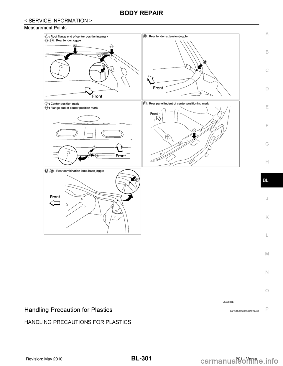
Measurement Points
Handling Precaution for PlasticsINFOID:0000000005929453
HANDLING PRECAUTIONS FOR PLASTICS
LIIA2888E
Revision: May 2010
2011 Versa
Page 812 of 3787

BL-302
< SERVICE INFORMATION >
BODY REPAIR
1. When repairing and painting a portion of the body adjacent to plastic parts, consider their characteristics
(influence of heat and solvent) and remove them if neces sary or take suitable measures to protect them.
2. Plastic parts should be repaired and painted using methods suiting the materials
, characteristics.
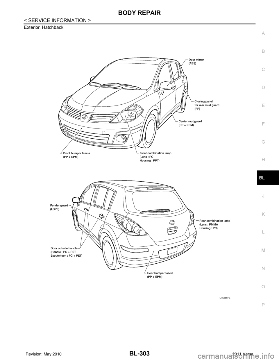
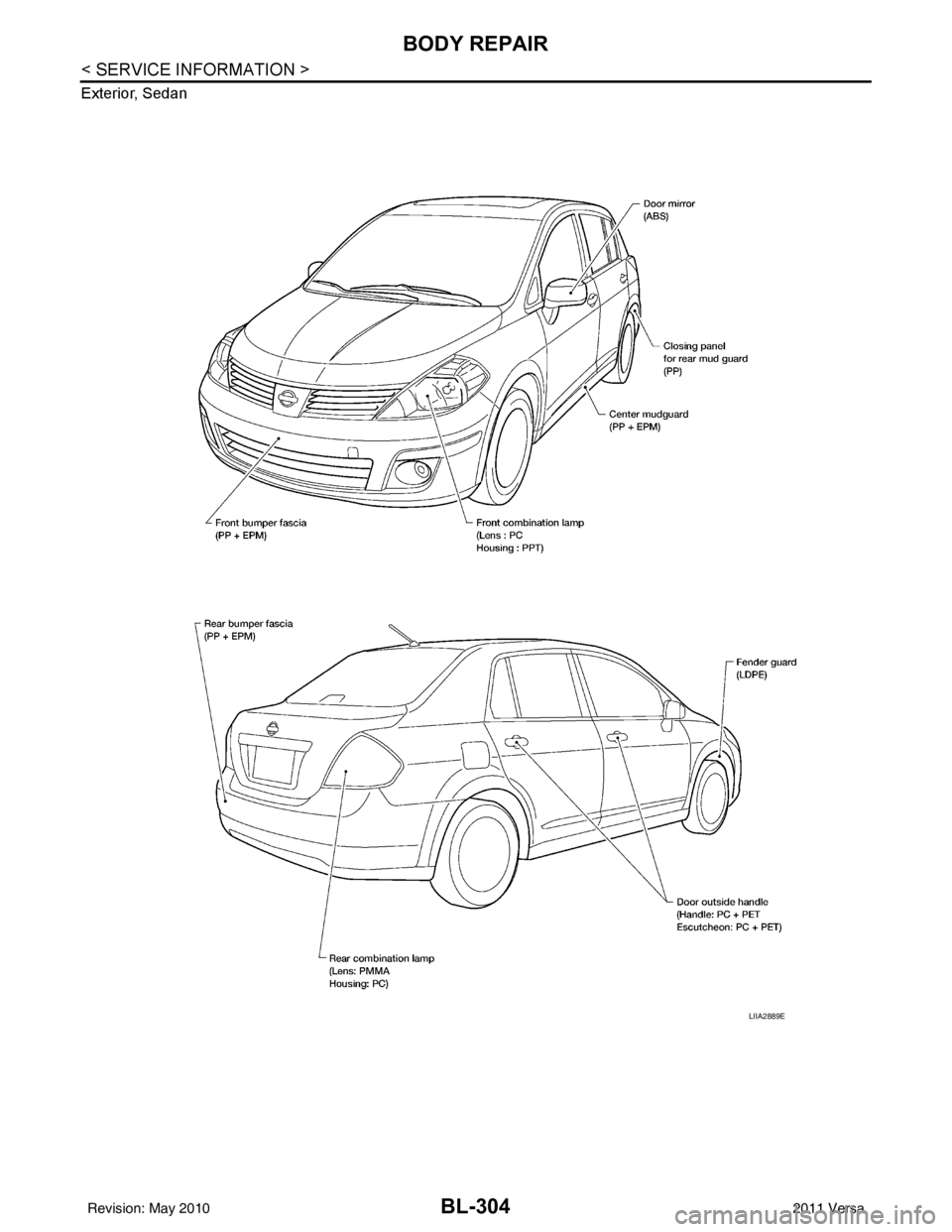
LOCATION OF PLASTIC PARTS
Abbre- viation Material name Heat resisting
temperature °C ( °F) Resistance to gasoline and
solvents Other cautions
PE Polyethylene 60 (140)Gasoline and most solvents are
harmless if applied for a very
short time (wipe up quickly). Flammable
PVC Polyvinyl Chloride 80 (176) Same as above. Poison gas is emitted
when burned.
EPM/
EPDM Ethylene Propylene (Diene) rub-
ber
80 (176) Same as above.
Flammable
TPO/
TPR Thermoplastic Olefine/
Thermoplastic Rubber
80 (176) Same as above.
Flammable
PP Polypropylene 90 (194) Same as above. Flammable, avoid bat-
tery acid.
UP Polyester thermoset 90 (194) Same as above. Flammable
PS Polystyrene 80 (176) Avoid solvents. Flammable
ABS Acrylonitrile Butadiene Styrene
resin
80 (176) Avoid gasoline and solvents.
AES Acrylonitrile Ethylene Styrene 80 (176) Same as above.
PMMA Polymethyl Methacrylate 85 (185) Same as above.
AAS Acrylonitrile Acrylic Styrene 85 (185) Same as above.
AS Acrylonitrile Styrene 85 (185) Same as above.
EVA Polyvinyl Ethyl Acetate 90 (194) Same as above.
ASA Acrylonitrile Styrene Acrylate 100 (222) Same as above. Flammable
PPO/
PPE Polyphenylene Oxide/
Polyphenylene Ether
110 (230) Same as above.
PC Polycarbonate 120 (248) Same as above.
PAR Polyacrylate 180 (356) Same as above.
L-
LDPE Lenear Low Density PE
45 (100)Gasoline and most solvents are
harmless. Flammable
PUR Polyurethane 90 (194) Same as above.
TPU Thermoplastic Urethane 110 (230) Same as above.
PPC Polypropylene Composite 115 (239) Same as above. Flammable
POM Polyacetal 120 (248) Same as above. Avoid battery acid.
PBT+P
C Polybutylene Terephtha-
late+Polycarbonate
120 (248) Same as above.
Flammable
PA Polyamide (Nylon) 140 (284) Same as above. Avoid immersing in wa-
ter.
PBT Polybutylene Terephthalate 140 (284) Same as above.
FRP Fiber Reinforced Plastics 170 (338) Same as above. Avoid battery acid.
PET Polyethylene Terephthalate 180 (356) Same as above.
PEI Polyetherimide 200 (392) Same as above.
Revision: May 2010 2011 Versa
Page 813 of 3787
BODY REPAIRBL-303
< SERVICE INFORMATION >
C
DE
F
G H
J
K L
M A
B
BL
N
O P
Exterior, Hatchback
LIIA2587E
Revision: May 2010
2011 Versa
Page 814 of 3787
BL-304
< SERVICE INFORMATION >
BODY REPAIR
Exterior, Sedan
LIIA2889E
Revision: May 20102011 Versa
Page 815 of 3787
BODY REPAIRBL-305
< SERVICE INFORMATION >
C
DE
F
G H
J
K L
M A
B
BL
N
O P
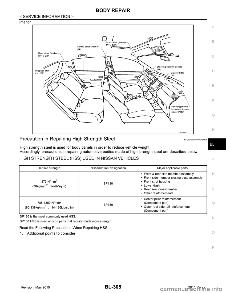
Interior
Precaution in Repairing High Strength SteelINFOID:0000000005929454
High strength steel is used for body panels in order to reduce vehicle weight.
Accordingly, precautions in repairing automotive bodies made of high strength steel are described below:
HIGH STRENGTH STEEL (HSS) USED IN NISSAN VEHICLES
SP130 is the most commonly used HSS.
SP150 HSS is used only on parts that require much more strength.
Read the Following Precautions When Repairing HSS:
1. Additional points to consider
LIIA2588E
Tensile strength
Nissan/Infiniti designation Major applicable parts
373 N/mm
2
(38kg/mm2 ,54klb/sq in) SP130• Front & rear side member assembly
• Front side member closing plate assembly
• Front strut housing
• Lower dash
• Rear seat crossmember
• Other reinforcements
785-1350 N/mm
2
(80-138kg/mm2 , 114-196klb/sq in) SP150• Center pillar reinforcement
(Component part)
• Outer roof side rail reinforcement (Component part)
Revision: May 2010 2011 Versa
Page 816 of 3787
BL-306
< SERVICE INFORMATION >
BODY REPAIR
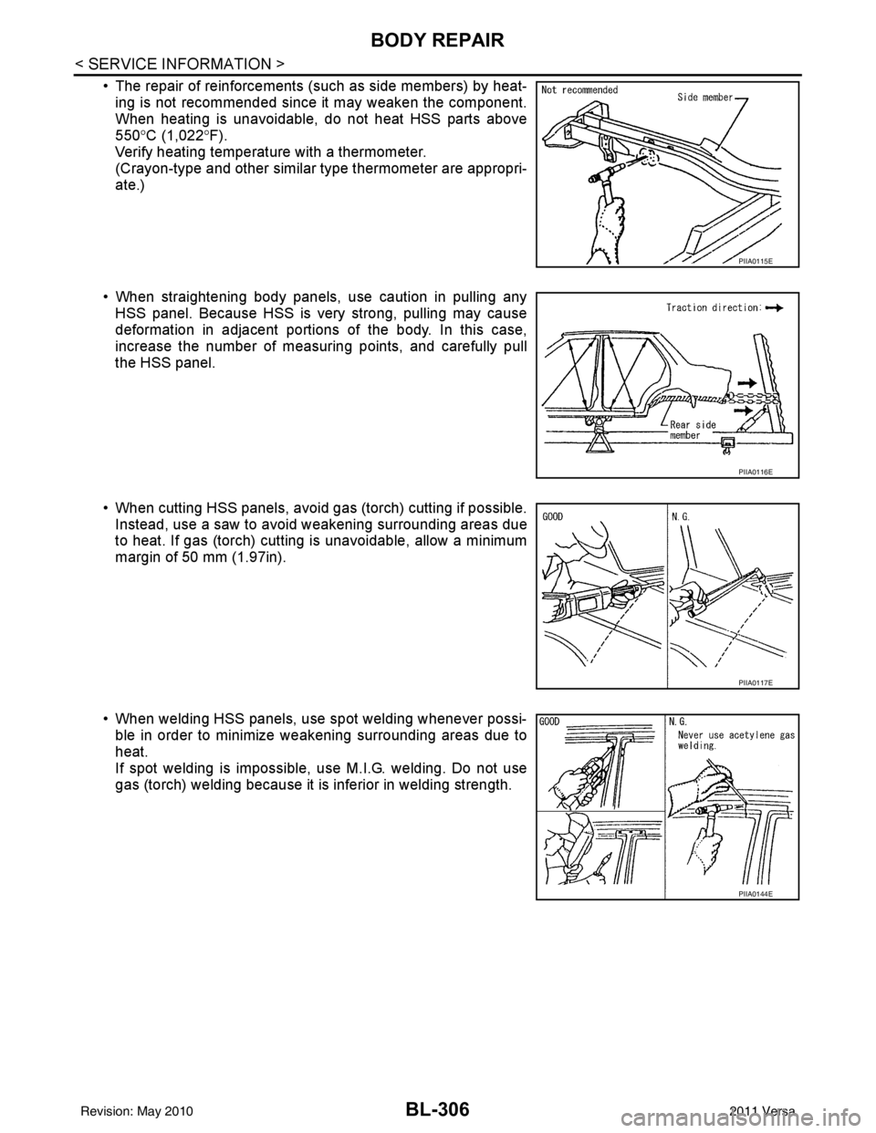
• The repair of reinforcements (such as side members) by heat-ing is not recommended since it may weaken the component.
When heating is unavoidable, do not heat HSS parts above
550° C (1,022° F).
Verify heating temperature with a thermometer.
(Crayon-type and other similar type thermometer are appropri-
ate.)
• When straightening body panels, use caution in pulling any HSS panel. Because HSS is very strong, pulling may cause
deformation in adjacent portions of the body. In this case,
increase the number of measuring points, and carefully pull
the HSS panel.
• When cutting HSS panels, avoid gas (torch) cutting if possible. Instead, use a saw to avoid weakening surrounding areas due
to heat. If gas (torch) cutting is unavoidable, allow a minimum
margin of 50 mm (1.97in).
• When welding HSS panels, use spot welding whenever possi- ble in order to minimize weakening surrounding areas due to
heat.
If spot welding is impossible, use M.I.G. welding. Do not use
gas (torch) welding because it is inferior in welding strength.
PIIA0115E
PIIA0116E
PIIA0117E
PIIA0144E
Revision: May 2010 2011 Versa
Page 817 of 3787
BODY REPAIRBL-307
< SERVICE INFORMATION >
C
DE
F
G H
J
K L
M A
B
BL
N
O P
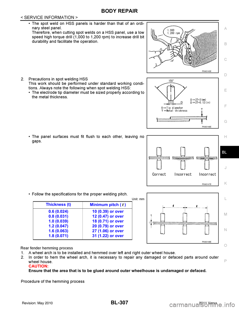
• The spot weld on HSS panels is harder than that of an ordi- nary steel panel.
Therefore, when cutting spot welds on a HSS panel, use a low
speed high torque drill (1,000 to 1,200 rpm) to increase drill bit
durability and facilitate the operation.
2. Precautions in spot welding HSS This work should be performed under standard working condi-
tions. Always note the following when spot welding HSS:
• The electrode tip diameter must be sized properly according tothe metal thickness.
• The panel surfaces must fit flush to each other, leaving no gaps.
• Follow the specifications for the proper welding pitch.
Unit: mm
Rear fender hemming process
1. A wheel arch is to be installed and hemmed over left and right outer wheel house.
2. In order to hem the wheel arch, it is necessary to repair any damaged or defaced parts around outer wheel house.
CAUTION:
Ensure that the area that is to be glued around outer wheelhouse is undamaged or defaced.
Procedure of the hemming process
PIIA0145E
PIIA0146E
PIIA0147E
Thickness (t) Minimum pitch ( )
0.6 (0.024)
0.8 (0.031)
1.0 (0.039)
1.2 (0.047)
1.6 (0.063)
1.8 (0.071) 10 (0.39) or over
12 (0.47) or over
18 (0.71) or over
20 (0.79) or over
27 (1.06) or over
31 (1.22) or over
PIIA0148E
Revision: May 2010
2011 Versa
Page 818 of 3787
BL-308
< SERVICE INFORMATION >
BODY REPAIR
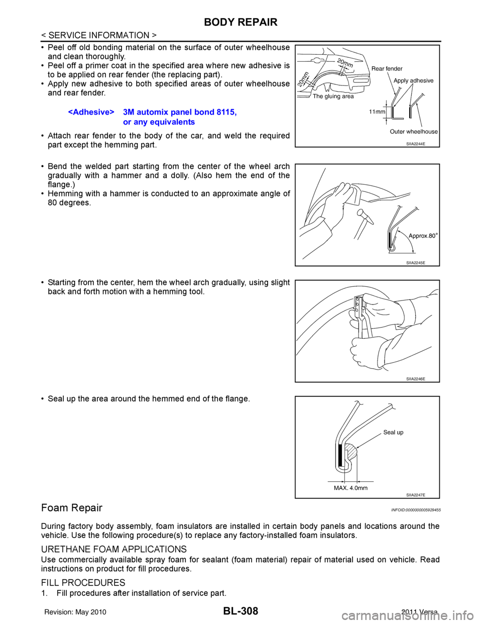
• Peel off old bonding material on the surface of outer wheelhouseand clean thoroughly.
• Peel off a primer coat in the specified area where new adhesive is
to be applied on rear fender (the replacing part).
• Apply new adhesive to both specified areas of outer wheelhouse and rear fender.
• Attach rear fender to the body of the car, and weld the required part except the hemming part.
• Bend the welded part starting from the center of the wheel arch
gradually with a hammer and a dolly. (Also hem the end of the
flange.)
• Hemming with a hammer is conducted to an approximate angle of
80 degrees.
• Starting from the center, hem the wheel arch gradually, using slight back and forth motion with a hemming tool.
• Seal up the area around the hemmed end of the flange.
Foam RepairINFOID:0000000005929455
During factory body assembly, foam insulators are installed in certain body panels and locations around the
vehicle. Use the following procedure(s) to replace any factory-installed foam insulators.
URETHANE FOAM APPLICATIONS
Use commercially available spray foam for sealant (foam material) repair of material used on vehicle. Read
instructions on product for fill procedures.
FILL PROCEDURES
1. Fill procedures after installation of service part.
or any equivalents
SIIA2244E
SIIA2245E
SIIA2246E
SIIA2247E
Revision: May 2010 2011 Versa
Page 819 of 3787
BODY REPAIRBL-309
< SERVICE INFORMATION >
C
DE
F
G H
J
K L
M A
B
BL
N
O P
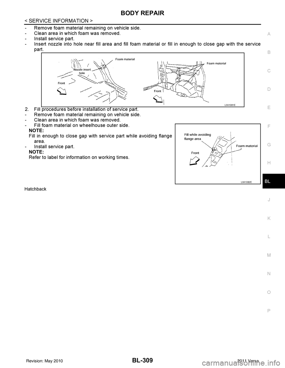
- Remove foam material remaining on vehicle side.
- Clean area in which foam was removed.
- Install service part.
- Insert nozzle into hole near fill area and fill foam material or fill in enough to close gap with the service part.
2. Fill procedures before installation of service part.
- Remove foam material remaining on vehicle side.
- Clean area in which foam was removed.
- Fill foam material on wheelhouse outer side. NOTE:
Fill in enough to close gap with service part while avoiding flange
area.
- Install service part.
NOTE:
Refer to label for information on working times.
Hatchback
LIIA1081E
LIIA1082E
Revision: May 2010 2011 Versa
Page 820 of 3787
BL-310
< SERVICE INFORMATION >
BODY REPAIR
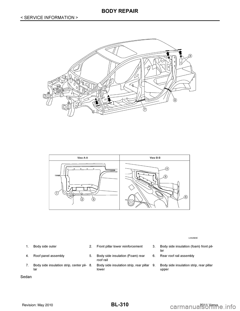
Sedan
1. Body side outer2. Front pillar lower reinforcement 3. Body side insulation (foam) front pil-
lar
4. Roof panel assembly 5. Body side insulation (Foam) rear
roof rail 6. Rear roof rail assembly
7. Body side insulation strip, center pil- lar 8. Body side insulation strip, rear pillar
lower 9. Body side insulation strip, rear pillar
upper
LIIA2665E
Revision: May 2010 2011 Versa