mirror NISSAN LATIO 2011 Service Repair Manual
[x] Cancel search | Manufacturer: NISSAN, Model Year: 2011, Model line: LATIO, Model: NISSAN LATIO 2011Pages: 3787, PDF Size: 78.35 MB
Page 1 of 3787

-1
QUICK REFERENCE INDEX
AGENERAL INFORMATIONGIGeneral Information
BENGINEEMEngine Mechanical
LUEngine Lubrication System
COEngine Cooling System
ECEngine Control System
FLFuel System
EXExhaust System
ACCAccelerator Control System
CTRANSMISSION/
TRANSAXLECLClutch System
MTManual Transaxle
ATAutomatic Transaxle
CVTCVT
DDRIVELINE/AXLEFAXFront Axle
RAXRear Axle
ESUSPENSIONFSUFront Suspension
RSURear Suspension
WTRoad Wheels & Tires
FBRAKESBRBrake System
PBParking Brake System
BRCBrake Control System
GSTEERINGPSPower Steering System
STCSteering Control System
HRESTRAINTSSBSeat Belts
SRSSupplemental Restraint System (SRS)
IBODYBLBody, Lock & Security System
GWGlasses, Window System & Mirrors
RFRoof
EIExterior & Interior
IPInstrument Panel
SESeat
JAIR CONDITIONERMTCManual Air Conditioner
KELECTRICALSCStarting & Charging System
LTLighting System
DIDriver Information System
WWWiper, Washer & Horn
BCSBody Control System
LANLAN System
AVAudio Visual, Navigation & Telephone System
ACSAuto Cruise Control System
PGPower Supply, Ground & Circuit Elements
LMAINTENANCEMAMaintenance
Edition: May 2010
Revision: May 2010
Publication No. SM1E-1C11U0
B
D
© 2010 NISSAN NORTH AMERICA, INC.
All rights reserved. No part of this Service Manual may be reproduced or stored in a retrieval system, or transmitted in any
form, or by any means, electronic, mechanical, photo-copying, recording or otherwise, without the prior written permission
of Nissan North America Inc.
A
C
E
F
G
H
I
J
K
L
M
Page 775 of 3787

BODY REPAIRBL-265
< SERVICE INFORMATION >
C
DE
F
G H
J
K L
M A
B
BL
N
O P
BODY REPAIR
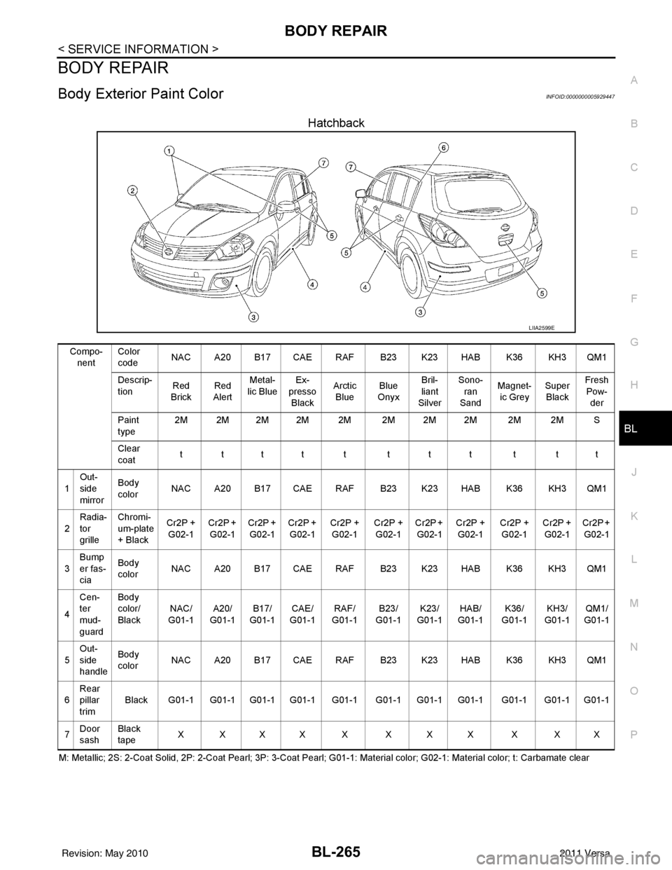
Body Exterior Paint ColorINFOID:0000000005929447
Hatchback
M: Metallic; 2S: 2-Coat Solid, 2P: 2-Coat Pearl; 3P: 3-Coat Pearl; G01-1: Material color; G02-1: Material color; t: Carbamate c lear
LIIA2599E
Compo-
nent Color
code
NAC A20 B17 CAE RAF B23 K23 HAB K36 KH3 QM1
Descrip-
tion Red
Brick Red
Alert Metal-
lic Blue Ex-
presso
Black Arctic
Blue Blue
Onyx Bril-
liant
Silver Sono-
ran
Sand Magnet-
ic Grey Super
Black Fresh
Pow-
der
Paint
type 2M 2M 2M 2M 2M 2M 2M 2M 2M 2M S
Clear
coat tttt t ttt t tt
1 Out-
side
mirror Body
color
NAC A20 B17 CAE RAF B23 K23 HAB K36 KH3 QM1
2 Radia-
tor
grille Chromi-
um-plate
+ Black
Cr2P +
G02-1 Cr2P +
G02-1 Cr2P +
G02-1 Cr2P +
G02-1 Cr2P +
G02-1 Cr2P +
G02-1 Cr2P +
G02-1 Cr2P +
G02-1 Cr2P +
G02-1 Cr2P +
G02-1 Cr2P +
G02-1
3 Bump
er fas-
cia Body
color
NAC A20 B17 CAE RAF B23 K23 HAB K36 KH3 QM1
4 Cen-
ter
mud-
guard Body
color/
Black
NAC/
G01-1 A20/
G01-1 B17/
G01-1 CAE/
G01-1 RAF/
G01-1 B23/
G01-1 K23/
G01-1 HAB/
G0 1-
1 K36/
G01
-1KH3/
G01-1 QM1/
G01-1
5 Out-
side
handle Body
color
NAC A20 B17 CAE RAF B23 K23 HAB K36 KH3 QM1
6 Rear
pillar
trim Black G01-1 G01-1 G01-1 G01-1 G01-1 G01-1 G01-1 G01-1 G01-1 G01-1 G01-1
7 Door
sash Black
tape
XXXX X XXX X XX
Revision: May 2010
2011 Versa
Page 776 of 3787

BL-266
< SERVICE INFORMATION >
BODY REPAIR
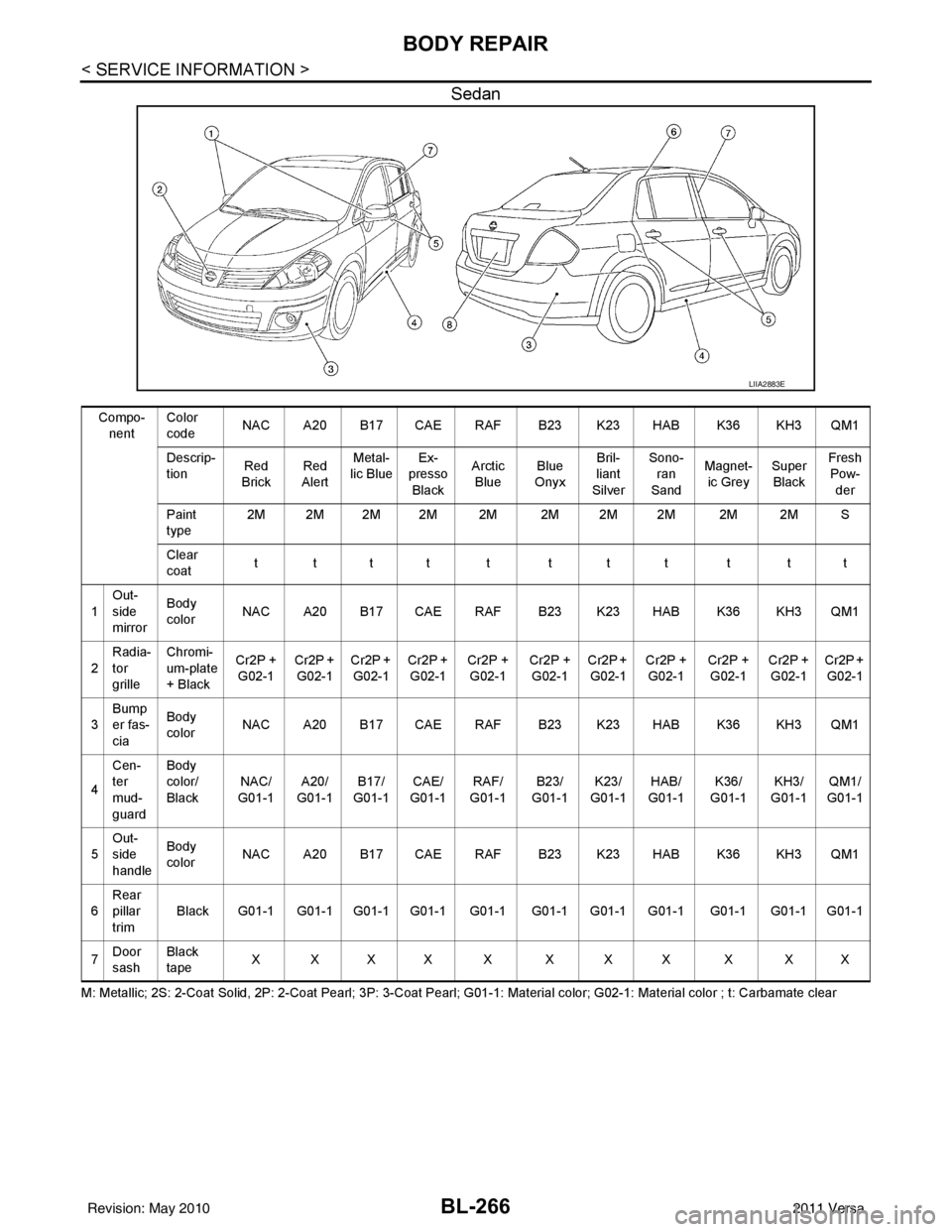
Sedan
M: Metallic; 2S: 2-Coat Solid, 2P: 2-Coat Pearl; 3P: 3-Coat Pearl; G01-1: Material color; G02-1: Material color ; t: Carbamate clear
LIIA2883E
Compo-
nent Color
code
NAC A20 B17 CAE RAF B23 K23 HAB K36 KH3 QM1
Descrip-
tion Red
Brick Red
Alert Metal-
lic Blue Ex-
presso
Black Arctic
Blue Blue
Onyx Bril-
liant
Silver Sono-
ran
Sand Magnet-
ic Grey Super
Black Fresh
Pow-
der
Paint
type 2M 2M 2M 2M 2M 2M 2M 2M 2M 2M S
Clear
coat tttt t ttt t tt
1 Out-
side
mirror Body
color
NAC A20 B17 CAE RAF B23 K23 HAB K36 KH3 QM1
2 Radia-
tor
grille Chromi-
um-plate
+ Black
Cr2P +
G02-1 Cr2P +
G02-1 Cr2P +
G02-1 Cr2P +
G02-1 Cr2P +
G02-1 Cr2P +
G02-1 Cr2P +
G02-1 Cr2P +
G02-1 Cr2P +
G02-1 Cr2P +
G02-1 Cr2P +
G02-1
3 Bump
er fas-
cia Body
color
NAC A20 B17 CAE RAF B23 K23 HAB K36 KH3 QM1
4 Cen-
ter
mud-
guard Body
color/
Black
NAC/
G01-1 A20/
G01-1 B17/
G01-1 CAE/
G01-1 RAF/
G01-1 B23/
G01-1 K23/
G01-1 HAB/
G0 1-1 K36/
G0 1-
1KH3/
G01-1 QM1/
G01-1
5 Out-
side
handle Body
color
NAC A20 B17 CAE RAF B23 K23 HAB K36 KH3 QM1
6 Rear
pillar
trim
Black G01-1 G01-1 G01-1 G01-1 G01-1 G01-1 G01-1 G01-1 G01-1 G01-1 G01-1
7 Door
sash Black
tape
XXXX X XXX X XX
Revision: May 2010
2011 Versa
Page 922 of 3787
![NISSAN LATIO 2011 Service Repair Manual WHEEL SENSORSBRC-33
< SERVICE INFORMATION > [ABS]
C
D
E
G H
I
J
K L
M A
B
BRC
N
O P
WHEEL SENSORS
Removal and InstallationINFOID:0000000005928457
NOTE:
The top portion of the figure (front side) shows NISSAN LATIO 2011 Service Repair Manual WHEEL SENSORSBRC-33
< SERVICE INFORMATION > [ABS]
C
D
E
G H
I
J
K L
M A
B
BRC
N
O P
WHEEL SENSORS
Removal and InstallationINFOID:0000000005928457
NOTE:
The top portion of the figure (front side) shows](/img/5/57357/w960_57357-921.png)
WHEEL SENSORSBRC-33
< SERVICE INFORMATION > [ABS]
C
D
E
G H
I
J
K L
M A
B
BRC
N
O P
WHEEL SENSORS
Removal and InstallationINFOID:0000000005928457
NOTE:
The top portion of the figure (front side) shows the view from LH side of the vehicle. The RH side is the mirror image of the L H side.
FRONT WHEEL SENSOR
Removal
CAUTION:
• As much as possible, avoid rotating wheel sensor when removing it. Pull wheel sensors out without
pulling on sensor harness.
• Take care to avoid damaging wheel sensor edges or rotor teeth. Remove wheel sensor first before removing front or rear wheel hub. This is to avo id damage to wheel sensor wiring and loss of sensor
function.
1. Remove the front wheel and tire. Refer to WT-7, "
Adjustment".
2. Remove the front fender protector. Refer to EI-26, "
Removal and Installation".
3. Disconnect the front w heel sensor connector.
4. Remove the front wheel sensor.
Installation
Installation is in the reverse order of removal.
CAUTION:
• When installing, make sure there is no foreign mate rial such as iron chips on and in the mounting
hole of the wheel sensor. Make sure no foreign material has been caught in the sensor rotor. Remove
any foreign material and clean the mount.
A. Front B. Rear1. Front wheel sensor connector (LH)
2. Front wheel sensor (LH) 3. Rear wheel sensor (LH)4. Rear wheel sensor connector (LH)
5. Rear wheel sensor connector (RH) 6. Rear wheel sensor (RH) 7. Side member
8. LH side 9. RH side Front
SFIA3090E
Revision: May 2010 2011 Versa
Page 975 of 3787
![NISSAN LATIO 2011 Service Repair Manual BRC-86
< SERVICE INFORMATION >[VDC/TCS/ABS]
WHEEL SENSORS
WHEEL SENSORS
Removal and InstallationINFOID:0000000005928507
NOTE:
The top portion of the figure (front side) shows the view from LH side of NISSAN LATIO 2011 Service Repair Manual BRC-86
< SERVICE INFORMATION >[VDC/TCS/ABS]
WHEEL SENSORS
WHEEL SENSORS
Removal and InstallationINFOID:0000000005928507
NOTE:
The top portion of the figure (front side) shows the view from LH side of](/img/5/57357/w960_57357-974.png)
BRC-86
< SERVICE INFORMATION >[VDC/TCS/ABS]
WHEEL SENSORS
WHEEL SENSORS
Removal and InstallationINFOID:0000000005928507
NOTE:
The top portion of the figure (front side) shows the view from LH side of the vehicle. The RH side is the mirror image of the LH side.
FRONT WHEEL SENSOR
Removal
CAUTION:
• As much as possible, avoid rotating wheel sensor when removing it
. Pull wheel sensors out without
pulling on sensor harness.
• Take care to avoid damaging wheel sensor edges or rotor teeth. Remove wheel sensor first before
removing front or rear wheel hub. This is to avoid damage to wheel sensor wiring and loss of sensor
function.
1. Remove the front wheel and tire. Refer to WT-7, "
Adjustment".
2. Remove the front fender protector. Refer to EI-26, "
Removal and Installation".
3. Disconnect the front wheel sensor connector.
4. Remove the front wheel sensor.
Installation
Installation is in the reverse order of removal.
CAUTION:
• When installing, make sure there is no foreign material such as iron chips on and in the mounting
hole of the wheel sensor. Make sure no foreign material has been caught in the sensor rotor. Remove
any foreign material and clean the mount.
A. Front B. Rear 1. Front wheel sensor connector (LH)
2. Front wheel sensor (LH) 3. Rear wheel sensor (LH)4. Rear wheel sensor connector (LH)
5. Rear wheel sensor connector (RH) 6. Rear wheel sensor (RH) 7. Side member
8. LH side 9. RH side Front
SFIA3090E
Revision: May 2010 2011 Versa
Page 2428 of 3787
![NISSAN LATIO 2011 Service Repair Manual EM-38
< ON-VEHICLE REPAIR >[HR16DE]
FUEL INJECTOR AND FUEL TUBE
Use mirrors for checking at points out of clear sight.
CAUTION:
Never touch the engine immediately after it is
stopped, as the engine b NISSAN LATIO 2011 Service Repair Manual EM-38
< ON-VEHICLE REPAIR >[HR16DE]
FUEL INJECTOR AND FUEL TUBE
Use mirrors for checking at points out of clear sight.
CAUTION:
Never touch the engine immediately after it is
stopped, as the engine b](/img/5/57357/w960_57357-2427.png)
EM-38
< ON-VEHICLE REPAIR >[HR16DE]
FUEL INJECTOR AND FUEL TUBE
Use mirrors for checking at points out of clear sight.
CAUTION:
Never touch the engine immediately after it is
stopped, as the engine becomes extremely hot.
Revision: May 2010 2011 Versa
Page 2548 of 3787
![NISSAN LATIO 2011 Service Repair Manual EM-158
< SERVICE INFORMATION >[MR18DE]
FUEL INJECTOR AND FUEL TUBE
*Power steering fluid, brake fluid, etc.
NOTE:
Use mirrors for checking at points out of clear sight.
CAUTION:
Never touch the engine NISSAN LATIO 2011 Service Repair Manual EM-158
< SERVICE INFORMATION >[MR18DE]
FUEL INJECTOR AND FUEL TUBE
*Power steering fluid, brake fluid, etc.
NOTE:
Use mirrors for checking at points out of clear sight.
CAUTION:
Never touch the engine](/img/5/57357/w960_57357-2547.png)
EM-158
< SERVICE INFORMATION >[MR18DE]
FUEL INJECTOR AND FUEL TUBE
*Power steering fluid, brake fluid, etc.
NOTE:
Use mirrors for checking at points out of clear sight.
CAUTION:
Never touch the engine immediately after it is
stopped, as the engine becomes extremely hot.
ItemBefore starting engine Engine runningAfter engine stopped
Engine coolant LevelLeakage Level
Engine oil LevelLeakage Level
Transmission/
transaxle fluid A/T and CVT Models
LeakageLevel/Leakage Leakage
M/T Models Level/Leakage LeakageLevel/Leakage
Other oils and fluids* LevelLeakage Level
Fuel LeakageLeakage Leakage
Exhaust gas —Leakage —
Revision: May 2010 2011 Versa
Page 2746 of 3787

GI-42
< SERVICE INFORMATION >
RECOMMENDED CHEMICAL PRODUCTS AND SEALANTS
RECOMMENDED CHEMICAL PRODUCTS AND SEALANTS
Recommended Chemical Product and SealantINFOID:0000000005929739
Refer to the following chart for help in selecting the appropriate chemical product or sealant.
Product Description PurposeNissan North America
Part No. (USA) Nissan Canada Part
No. (Canada) Aftermarket Cross-
reference Part Nos.
1 Rear View Mirror Adhe-
sive Used to permanently re-
mount rear view mirrors to
windows.
999MP-AM000P 99998-50505
Permatex 81844
2 Anaerobic Liquid Gas-
ket For metal-to-metal flange
sealing.
Can fill a 0.38 mm (0.015
inch) gap and provide in-
stant sealing for most pow-
ertrain applications.
999MP-AM001P 99998-50503
Permatex 51813 and
51817
3 High Performance
Thread Sealant Provides instant sealing on
any threaded straight or
parallel threaded fitting.
(Thread sealant only, no
locking ability.)
• Do not use on plastic.
999MP-AM002P 999MP-AM002P Permatex 56521
4 Silicone RTV Gasket Maker
999MP-AM003P
(Ultra Grey)99998-50506
(Ultra Grey)Permatex Ultra Grey
82194;
Three Bond
1207,1215, 1216,
1217F, 1217G and
1217H
Nissan RTV Part No.
999MP-A7007
Gasket Maker for Maxima/
Quest 5-speed automatic
transmission
(RE5F22A) ––
Three Bond 1281B
or exact equivalent in
its quality
5 High Temperature,
High Strength Thread
Locking Sealant (Red)
Threadlocker
999MP-AM004P 999MP-AM004P Permatex 27200;
Three Bond 1360,
1360N, 1305 N&P,
1307N, 1335,
1335B, 1363B,
1377C, 1386B, D&E
and 1388
Loctite 648
6 Medium Strength
Thread Locking Seal-
ant (Blue) Threadlocker (service tool
removable)
999MP-AM005P 999MP-AM005P Permatex 24200,
24206, 24240,
24283 and 09178;
Three Bond 1322,
1322N, 1324 D&N,
1333D, 1361C,
1364D, 1370C and
1374
Revision: May 2010
2011 Versa
Page 2755 of 3787

GW-1
BODY
C
DE
F
G H
J
K L
M
SECTION GW
A
B
GW
N
O P
CONTENTS
GLASSES, WINDOW SYSTEM & MIRRORS
SERVICE INFORMATION .. ..........................3
PRECAUTIONS .............................................. .....3
Precaution for Supplemental Restraint System
(SRS) "AIR BAG" and "SEAT BELT PRE-TEN-
SIONER" ............................................................. ......
3
Precaution Necessary for Steering Wheel Rota-
tion After Battery Disconnect ............................... ......
3
Precaution for Procedure without Cowl Top Cover ......4
Handling for Adhesive and Primer ............................4
PREPARATION ...................................................5
Special Service Tools .......................................... ......5
Commercial Service Tool ..........................................5
SQUEAK AND RATTLE TROUBLE DIAG-
NOSES ................................................................
6
Work Flow ........................................................... ......6
Generic Squeak and Rattle Troubleshooting ............8
Diagnostic Worksheet .............................................10
WINDSHIELD GLASS ........................................12
Removal and Installation .........................................12
OPERA WINDOW GLASS .................................14
Removal and Installation .........................................14
REAR WINDOW GLASS AND MOLDING ..... ....16
Removal and Installation .........................................16
POWER WINDOW SYSTEM ..............................19
Component Parts and Harness Connector Loca-
tion ...................................................................... ....
19
System Description .................................................19
CAN Communication System Description ...............23
Schematic ...............................................................24
Wiring Diagram - WINDOW- ...................................25
Main Power Window and Door Lock/Unlock
Switch Harness Connector Terminal Layout ...........
29
Terminal and Reference Value for Main Power
Window and Door Lock/Unlock Switch ...................
29
Terminal and Reference Value for BCM .................30
Work Flow ............................................................ ....30
CONSULT-III Function (BCM) .................................30
Power Window Auto Operat ion Initialization ............31
Trouble Diagnosis Symptom Chart ...................... ....31
BCM Power Supply and Ground Circuit Inspection
....
32
Main Power Window and Door Lock/Unlock
Switch Power Supply and Ground Circuit Inspec-
tion ....................................................................... ....
32
Front Power Window Motor LH Circuit Inspection ....33
Front Power Window RH Circuit Inspection (Pow-
er Window and Door Lock/Unlock Switch RH Op-
eration) ....................................................................
34
Front Power Window Motor RH Circuit Inspection ....35
Encoder Circuit Inspection .......................................36
Door Switch Check ..................................................38
Rear Power Window LH Circuit Inspection (Rear
Power Window Switch LH Operation) .....................
39
Rear Power Window RH Circuit Inspection (Rear
Power Window Switch RH Operation) ................. ....
40
Rear Power Window Motor LH Circuit Inspection ....40
Rear Power Window Motor RH Circuit Inspection ....42
FRONT DOOR GLASS AND REGULATOR .....44
Removal and Installation .........................................44
Disassembly and Assembly .....................................46
Inspection after Installation ......................................46
REAR DOOR GLASS AND REGULATOR .......48
Removal and Installation ..................................... ....48
Disassembly and Assembly .....................................50
Inspection after Installation ......................................50
REAR WINDOW DEFOGGER ..........................51
Component Parts and Harness Connector Loca-
tion ....................................................................... ....
51
System Description ..................................................51
CAN Communication System Description ...............52
Wiring Diagram - DEF - ...........................................53
Terminal and Reference Value for BCM ..................55
Terminal and Reference Value for IPDM E/R ...... ....55
Revision: May 2010 2011 Versa
Page 2756 of 3787

GW-2
Work Flow ...............................................................55
CONSULT-III Function (BCM) ................................55
Trouble Diagnosis Symptom Chart .........................55
BCM Power Supply and Ground Circuit Inspection
...
56
Rear Window Defogger Switch Circuit Inspection ...56
Rear Window Defogger Circ uit Inspection ..............57
Door Mirror Defogger Circu it Inspection .................60
Filament Check .................................................... ...61
Filament Repair .................................................... ...62
DOOR MIRROR .................................................64
Wiring Diagram - MIRROR - ................................ ...64
Removal and Installation .........................................65
Disassembly and Assembly ................................. ...65
INSIDE MIRROR ................................................67
Removal and Installation .........................................67
Revision: May 2010 2011 Versa