warning light NISSAN LEAF 2022 Owner´s Manual
[x] Cancel search | Manufacturer: NISSAN, Model Year: 2022, Model line: LEAF, Model: NISSAN LEAF 2022Pages: 618, PDF Size: 4.3 MB
Page 277 of 618
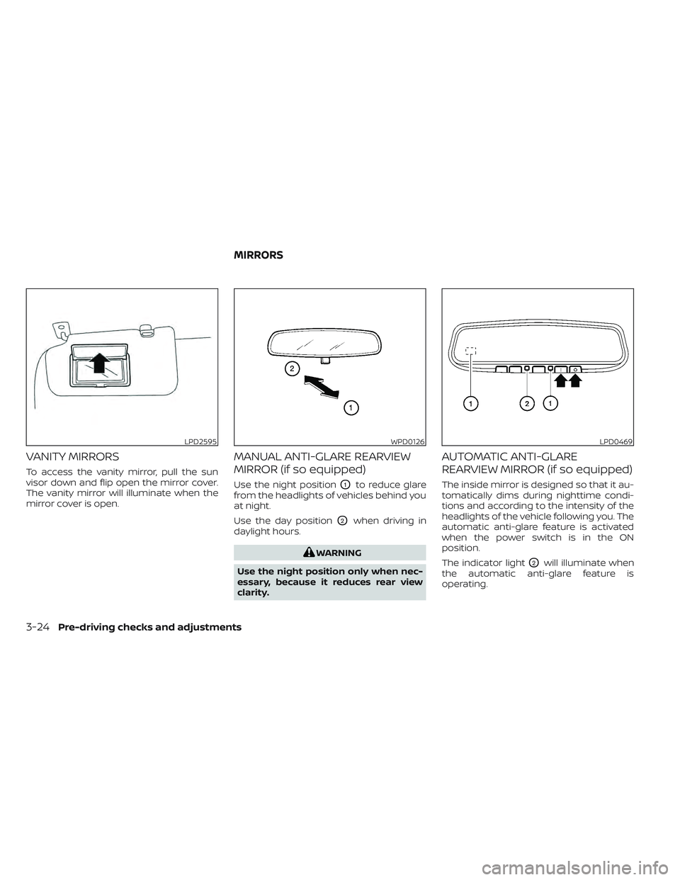
VANITY MIRRORS
To access the vanity mirror, pull the sun
visor down and flip open the mirror cover.
The vanity mirror will illuminate when the
mirror cover is open.
MANUAL ANTI-GLARE REARVIEW
MIRROR (if so equipped)
Use the night positionO1to reduce glare
from the headlights of vehicles behind you
at night.
Use the day position
O2when driving in
daylight hours.
WARNING
Use the night position only when nec-
essary, because it reduces rear view
clarity.
AUTOMATIC ANTI-GLARE
REARVIEW MIRROR (if so equipped)
The inside mirror is designed so that it au-
tomatically dims during nighttime condi-
tions and according to the intensity of the
headlights of the vehicle following you. The
automatic anti-glare feature is activated
when the power switch is in the ON
position.
The indicator light
O2will illuminate when
the automatic anti-glare feature is
operating.
LPD2595WPD0126LPD0469
MIRRORS
3-24Pre-driving checks and adjustments
Page 278 of 618
NOTE:
Do not hang any objects over the sen-
sors
O1or apply glass cleaner to the sen-
sors. Doing so will reduce the sensitivity
of the sensors, resulting in improper
operation.
The indicator light
O2will illuminate when
the automatic anti-glare feature is
operating.
To turn off the automatic anti-glare feature,
press the O button. The indicator light
will turn off.
To turn on the automatic anti-glare feature
again, press the | button again. The in-
dicator light will turn on.
For additional information, see “HomeLink®
Universal Transceiver” (P. 2-71).
OUTSIDE MIRRORS
The outside mirror remote control will op-
erate only when the power switch is in the
ACC or ON position.
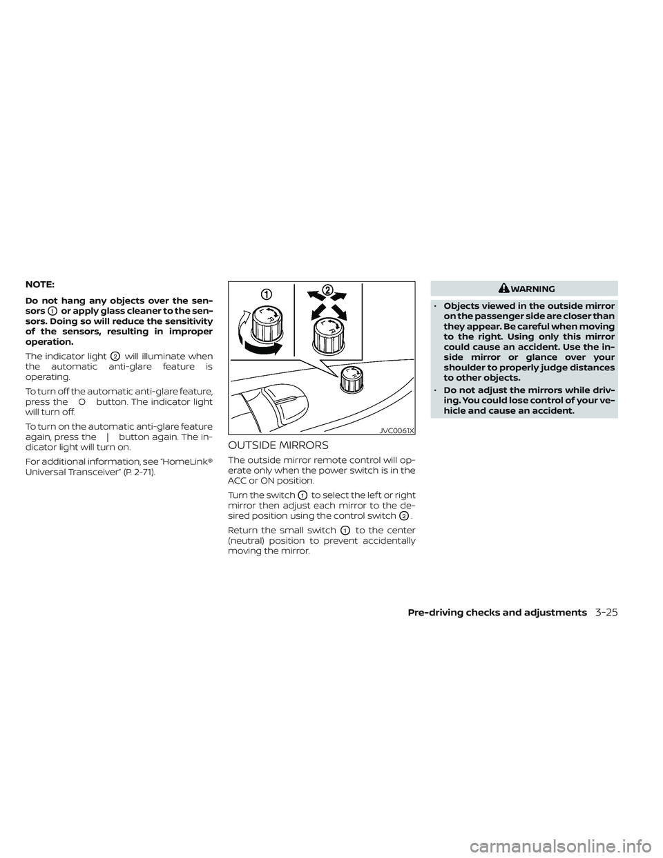
Turn the switch
O1to select the lef t or right
mirror then adjust each mirror to the de-
sired position using the control switch
O2.
Return the small switch
O1to the center
(neutral) position to prevent accidentally
moving the mirror.
WARNING
• Objects viewed in the outside mirror
on the passenger side are closer than
they appear. Be careful when moving
to the right. Using only this mirror
could cause an accident. Use the in-
side mirror or glance over your
shoulder to properly judge distances
to other objects.
• Do not adjust the mirrors while driv-
ing. You could lose control of your ve-
hicle and cause an accident.
JVC0061X
Pre-driving checks and adjustments3-25
Page 288 of 618
NOTE:Do not adjust any of the display set-
tings of the RearView Monitor while
the vehicle is moving. Make sure the
parking brake is firmly applied.
HOW TO TURN ON AND OFF
PREDICTED COURSE LINES
To toggle ON and OFF the predicted course
lines while in the P (Park) position:
1. Touch the “Settings” key.
2. Touch the “Camera” key.
3. Touch the “Predicted Course Lines” keyto turn the feature ON or OFF.
Pressing the CAMERA button while the shif t
lever is in the R (Reverse) position can also
turn on and off the predicted course lines.
REARVIEW MONITOR SYSTEM
LIMITATIONS
WARNING
Listed below are the system limitations
for RearView Monitor. Failure to oper-
ate the vehicle in accordance with
these system limitations could result in
serious injury or death. •
The system cannot completely elimi-
nate blind spots and may not show
every object.
• Underneath the bumper and the cor-
ner areas of the bumper cannot be
viewed on the RearView Monitor be-
cause of its monitoring range limita-
tion. The system will not show small
objects below the bumper, and may
not show objects close to the bum-
per or on the ground.
• Objects viewed in the RearView
Monitor differ from actual distance
because a wide-angle lens is used.
• Objects in the RearView Monitor will
appear visually opposite compared
to when viewed in the rearview and
outside mirrors.
• Use the displayed lines as a refer-
ence. The lines are highly affected by
the number of occupants, fuel level,
vehicle position, road conditions and
road grade.
• Make sure that the rear hatch is se-
curely closed when backing up.
• Do not put anything on the rearview
camera. The rearview camera is in-
stalled above the license plate. •
When washing the vehicle with high
pressure water, be sure not to spray it
around the camera. Otherwise, water
may enter the camera unit causing
water condensation on the lens, a
malfunction, fire or an electric shock.
• Do not strike the camera. It is a preci-
sion instrument. Otherwise, it may
malfunction or cause damage result-
ing in a fire or an electric shock.
The following are operating limitations and
do not represent a system malfunction:
• When the temperature is extremely high or low, the screen may not clearly display
objects.
• When strong light directly shines on the camera, objects may not be displayed
clearly.
• Vertical lines may be seen in objects on the screen. This is due to strong reflected
light from the bumper.
• The screen may flicker under fluorescent light.
• The colors of objects on the RearView Monitor may differ somewhat from the
actual color of objects.
• Objects on the monitor may not be clear in a dark environment.
Monitor, climate, audio, phone and voice recognition systems4-9
Page 292 of 618
When the camera is first activated with the
bird’s-eye view in the display, a red icon will
flash on the screen. This indicates that the
sonar system is activated. For additional
information on the rear sonar system, see
“Rear sonar system” (P. 5-168). The screen
displayed on the Intelligent Around View
Monitor will automatically return to the
previous screen 3 minutes af ter the CAM-
ERA button has been pressed with the shif t
lever in a position other than the R (Re-
verse) position.
Available views
WARNING
• The distance guide lines and the ve-
hicle width lines should be used as a
reference only when the vehicle is on
a paved, level surface. The apparent
distance viewed on the monitor may
be different than the actual distance
between the vehicle and displayed
objects.
• Use the displayed lines and the bird’s
eye view as a reference. The lines and
the bird’s-eye view are greatly af-
fected by the number of occupants,
cargo, fuel level, vehicle position,
road condition and road grade. •
If the tires are replaced with different
sized tires, the predicted course lines
and the bird’s-eye view may be dis-
played incorrectly.
• When driving the vehicle up a hill, ob-
jects viewed in the monitor are fur-
ther than they appear. When driving
the vehicle down a hill, objects
viewed in the monitor are closer than
they appear.
• Objects in the rear view will appear
visually opposite compared to when
viewed in the rear view and outside
mirrors.
• Use the mirrors or actually look to
properly judge distances to other
objects.
• On a snow-covered or slippery road,
there may be a difference between
the predicted course lines and the
actual course line.
• The vehicle width and predicted
course lines are wider than the actual
width and course.
• The displayed lines will appear
slightly off to the right, because the
rearview camera is not installed in
the rear center of the vehicle.
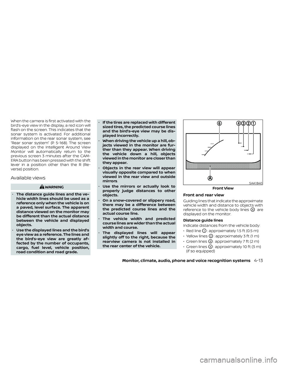
Front and rear view
Guiding lines that indicate the approximate
vehicle width and distance to objects with
reference to the vehicle body lines
OAare
displayed on the monitor.
Distance guide lines
Indicate distances from the vehicle body:
• Red line
O1: approximately 1.5 f t (0.5 m)
• Yellow lines
O2: approximately 3 f t (1 m)
• Green lines
O3: approximately 7 f t (2 m)
• Green lines
O4: approximately 10 f t (3 m)
(if so equipped)
SAA1840
Front View
Monitor, climate, audio, phone and voice recognition systems4-13
Page 294 of 618
Af ter the EV system is placed in the ON
position, the non-viewable areas
O2are
highlighted in yellow for several seconds
af ter the bird’s-eye view is displayed. It will
be shown only the first time af ter the
power switch is placed in the ON position.
WARNING
• Objects in the bird’s-eye view will ap-
pear further than the actual distance.
• Tall objects, such as a curb or vehicle,
may be misaligned or not displayed
at the seam of the views.
• Objects that are above the camera
cannot be displayed.
• The view for the bird’s-eye view may
be misaligned when the camera po-
sition alters.
• A line on the ground may be mis-
aligned and is not seen as being
straight at the seam of the views. The
misalignment will increase as the
line proceeds away from the vehicle.
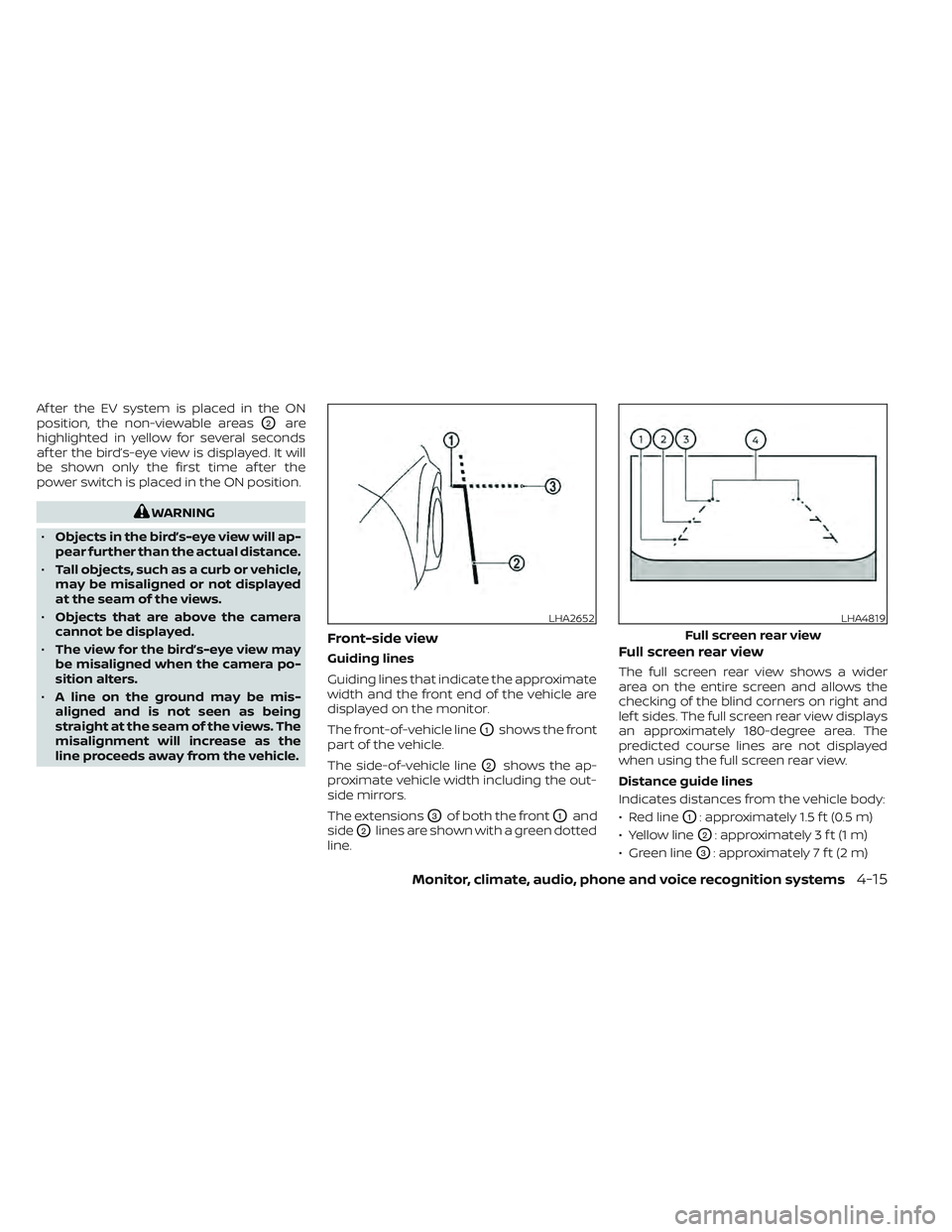
Front-side view
Guiding lines
Guiding lines that indicate the approximate
width and the front end of the vehicle are
displayed on the monitor.
The front-of-vehicle line
O1shows the front
part of the vehicle.
The side-of-vehicle line
O2shows the ap-
proximate vehicle width including the out-
side mirrors.
The extensions
O3of both the frontO1and
side
O2lines are shown with a green dotted
line.
Full screen rear view
The full screen rear view shows a wider
area on the entire screen and allows the
checking of the blind corners on right and
lef t sides. The full screen rear view displays
an approximately 180-degree area. The
predicted course lines are not displayed
when using the full screen rear view.
Distance guide lines
Indicates distances from the vehicle body:
• Red line
O1: approximately 1.5 f t (0.5 m)
• Yellow line
O2: approximately 3 f t (1 m)
• Green line
O3: approximately 7 f t (2 m)
LHA2652LHA4819
Full screen rear view
Monitor, climate, audio, phone and voice recognition systems4-15
Page 299 of 618
INTELLIGENT AROUND VIEW
MONITOR SYSTEM LIMITATIONS
WARNING
Listed below are the system limitations
for Intelligent Around View Monitor.
Failure to operate the vehicle in accor-
dance with these system limitations
could result in serious injury or death.
• Do not use the Intelligent Around
View Monitor with the outside mir-
rors in the stored position, and make
sure that the rear hatch is securely
closed when operating the vehicle
using the Intelligent Around View
Monitor.
• The apparent distance between ob-
jects viewed on the Intelligent
Around View Monitor differs from the
actual distance.
• The cameras are installed on the
front grille, the outside mirrors and
above the rear license plate. Do not
put anything on the vehicle that cov-
ers the cameras.
• When washing the vehicle with high
pressure water, be sure not to spray it
around the cameras. Otherwise, wa-
ter may enter the camera unit caus-
ing water condensation on the lens, a
malfunction, fire or an electric shock. •
Do not strike the cameras. They are
precision instruments. Doing so
could cause a malfunction or cause
damage resulting in a fire or an elec-
tric shock.
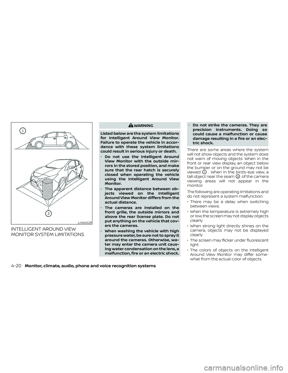
There are some areas where the system
will not show objects and the system does
not warn of moving objects. When in the
front or rear view display, an object below
the bumper or on the ground may not be
viewed
O1. When in the bird’s-eye view, a
tall object near the seam
O2of the camera
viewing areas will not appear in the
monitor.
The following are operating limitations and
do not represent a system malfunction:
• There may be a delay when switching between views.
• When the temperature is extremely high or low, the screen may not display objects
clearly.
• When strong light directly shines on the camera, objects may not be displayed
clearly.
• The screen may flicker under fluorescent light.
• The colors of objects on the Intelligent Around View Monitor may differ some-
what from the actual color of objects.
LHA4529
4-20Monitor, climate, audio, phone and voice recognition systems
Page 305 of 618
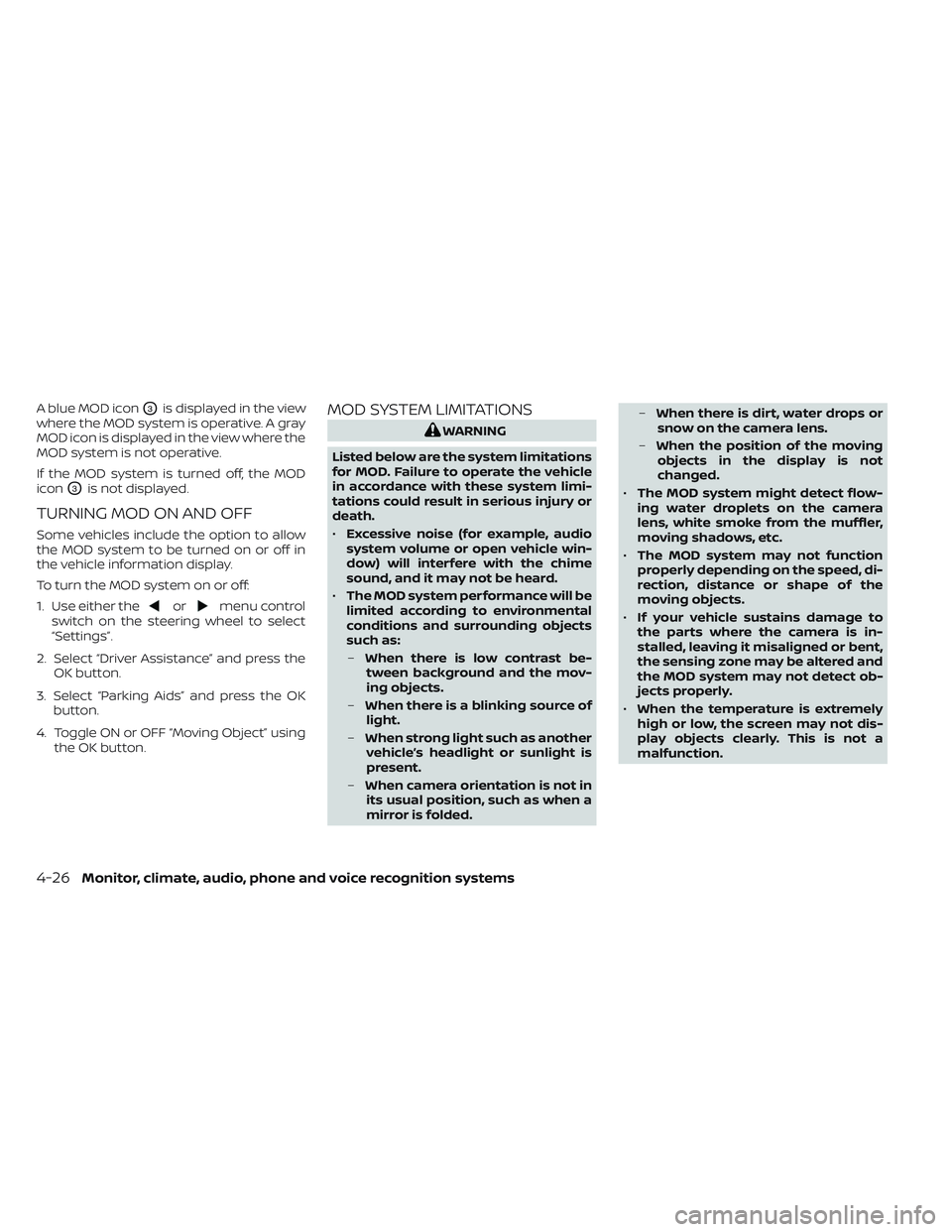
A blue MOD iconO3is displayed in the view
where the MOD system is operative. A gray
MOD icon is displayed in the view where the
MOD system is not operative.
If the MOD system is turned off, the MOD
icon
O3is not displayed.
TURNING MOD ON AND OFF
Some vehicles include the option to allow
the MOD system to be turned on or off in
the vehicle information display.
To turn the MOD system on or off:
1. Use either the
ormenu control
switch on the steering wheel to select
“Settings”.
2. Select “Driver Assistance” and press the OK button.
3. Select “Parking Aids” and press the OK button.
4. Toggle ON or OFF “Moving Object” using the OK button.
MOD SYSTEM LIMITATIONS
WARNING
Listed below are the system limitations
for MOD. Failure to operate the vehicle
in accordance with these system limi-
tations could result in serious injury or
death.
• Excessive noise (for example, audio
system volume or open vehicle win-
dow) will interfere with the chime
sound, and it may not be heard.
• The MOD system performance will be
limited according to environmental
conditions and surrounding objects
such as:
– When there is low contrast be-
tween background and the mov-
ing objects.
– When there is a blinking source of
light.
– When strong light such as another
vehicle’s headlight or sunlight is
present.
– When camera orientation is not in
its usual position, such as when a
mirror is folded. –
When there is dirt, water drops or
snow on the camera lens.
– When the position of the moving
objects in the display is not
changed.
• The MOD system might detect flow-
ing water droplets on the camera
lens, white smoke from the muffler,
moving shadows, etc.
• The MOD system may not function
properly depending on the speed, di-
rection, distance or shape of the
moving objects.
• If your vehicle sustains damage to
the parts where the camera is in-
stalled, leaving it misaligned or bent,
the sensing zone may be altered and
the MOD system may not detect ob-
jects properly.
• When the temperature is extremely
high or low, the screen may not dis-
play objects clearly. This is not a
malfunction.
4-26Monitor, climate, audio, phone and voice recognition systems
Page 308 of 618
WARNING
• The air conditioning cooling function
operates only when the power
switch is in the ON position or when
the READY to drive indicator light is
ON.
• Do not leave children or adults who
would normally require the assis-
tance of others alone in your vehicle.
Pets should also not be lef t alone.
They could accidentally injure them-
selves or others through inadvertent
operation of the vehicle. Also, on hot,
sunny days, temperatures in a closed
vehicle could quickly become high
enough to causes severe or possibly
fatal injuries to people or animals. •
Do not use the recirculation mode for
long periods as it may cause the inte-
rior air to become stale and the win-
dows to fog up.
NOTE:
• Odors from inside and outside the ve- hicle can build up in the air conditioner
unit. Odor can enter the passenger
compartment through the vents.
• When parking, set the heater or air conditioner controls to turn off air re-
circulation to allow fresh air into the
passenger compartment. This should
help reduce odors inside the vehicle. The climate control system (air conditioner
and heater functions) can be operated
when the READY to drive indicator light is
illuminated. However, while charging, the
climate control system can be used when
the power switch is in the ON position.
The fan, heater and air conditioning can be
turned on manually, using the timer func-
tion and using the remote climate control
function.
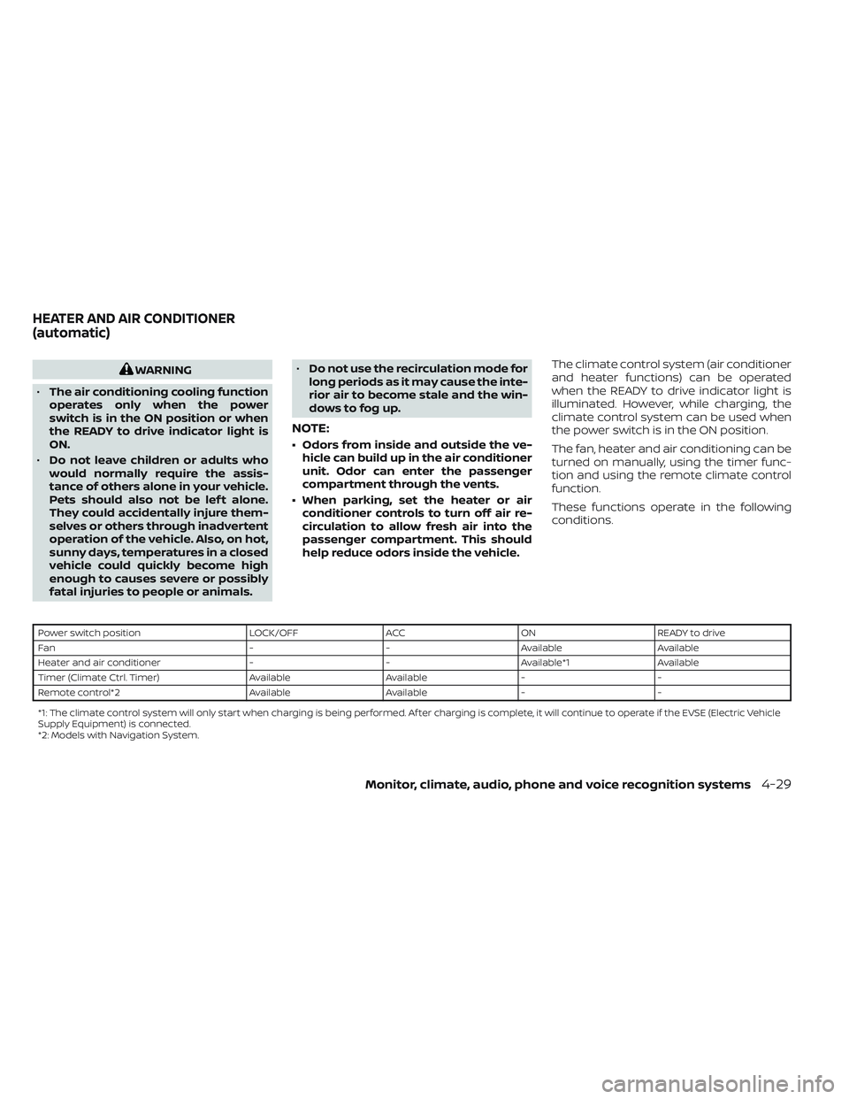
These functions operate in the following
conditions.
Power switch position
LOCK/OFFACCON READY to drive
Fan --Available Available
Heater and air conditioner --Available*1 Available
Timer (Climate Ctrl. Timer) AvailableAvailable- -
Remote control*2 AvailableAvailable- -
*1: The climate control system will only start when charging is being performed. Af ter charging is complete, it will continue to operate if the EVSE (El ectric Vehicle
Supply Equipment) is connected.
*2: Models with Navigation System.
HEATER AND AIR CONDITIONER
(automatic)
Monitor, climate, audio, phone and voice recognition systems4-29
Page 317 of 618
Temperature control
Press the temperature control buttons to
set the desired temperature.
Air recirculation
Press the
intake air control button to
change the air circulation mode. When the
indicator light illuminates, the flowing air is
recirculated inside the vehicle.
When the outside temperature exceeds
70°F (21°C) the air conditioning system may
default to air recirculation mode automati-
cally to reduce overall power consumption.
To exit air recirculation mode, deselect the
air recirculation button (indicator will turn
off ) to enter fresh mode.
Outside air circulation
Press the
intake air control button to
change the air circulation mode. When the
indicator light does not illuminate, the flow-
ing air is drawn from outside the vehicle.
Automatic air intake control
In the AUTO mode, the intake air will be
controlled automatically. When the outside
temperature exceeds 70°F (21°C), the air
conditioning system may default to air re-
circulation mode automatically to reduce
overall power consumption. To set the automatic control mode, press
and hold the
intake air control button.
The indicator light will blink twice and the
inside/outside circulation will then be con-
trolled automatically. When in automatic
mode, the indicator light will come on when
inside air recirculation is active.
Rear window and outside mirror (if so
equipped) defroster switch
For additional information, see “Rear win-
dow and outside mirror (if so equipped)
defroster switch” (P. 2-47).
To turn the system off
To turn off the climate control, press the
Climate control system ON·OFF button.
The same operating mode (Heater or A/C)
that was active when the system is turned
off is active when system is turned back on.
CLIMATE CTRL. TIMER
This function pre-heats or pre-cools the
passenger compartment of the vehicle to
the temperature before driving. This helps
reduce power consumption from the Li-ion
battery.
The Climate Ctrl. Timer operates the air
conditioner using power from the charger
or the Li-ion battery. While the charging connector is connected to the vehicle,
electric power from the Li-ion battery is not
used.
The Climate Ctrl. Timer function allows two
timer settings.
Once the Climate Ctrl. Timer is set, it will
complete air conditioning by the time that
is set. It is not necessary to set the Climate
Ctrl. Timer every day.
WARNING
Even if the Climate Ctrl. Timer is set, the
temperature in the passenger com-
partment may become high or low if
the system automatically stops. Do not
leave children or adults who would nor-
mally require the support of others
alone in your vehicle. Pets should not
be lef t alone either. On hot, sunny days,
temperatures in a closed vehicle could
quickly become high enough to cause
severe or possibly fatal injuries to
people or animals. Also on cold days,
temperature in a vehicle could become
low enough to cause severe or possible
fatal injuries to people or animals.
4-38Monitor, climate, audio, phone and voice recognition systems
Page 330 of 618
• The low tire pressure warning light doesnot automatically turn off when the tire
pressure is adjusted. Af ter the tire is in-
flated to the recommended pressure, the
vehicle must be driven at speeds above
16 mph (25 km/h) to activate the TPMS
and turn off the low tire pressure warning
light. Use a tire pressure gauge to check
the tire pressure.
• The “Tire Pressure Low - Add Air” warning also appears on the vehicle information
display when the low tire pressure warn-
ing light is illuminated and low tire pres-
sure is detected. The “Tire Pressure Low -
Add Air” warning turns off when the low
tire pressure warning light turns off.
• The “Tire Pressure Low - Add Air” warning appears each time the power switch is
placed in the ON position as long as the
low tire pressure warning light remains
illuminated.
• The “Tire Pressure Low - Add Air” warning does not appear if the low tire pressure
warning light illuminates to indicate a
TPMS malfunction. • Tire pressure rises and falls depending on
the heat caused by operation of the ve-
hicle and the outside temperature. Do
not reduce the tire pressure af ter driving
because the tire pressure rises af ter driv-
ing. Low outside temperature can lower
the temperature of the air inside the tire,
which can cause a lower tire inflation
pressure. This may cause the low tire
pressure warning light to illuminate. If the
warning light illuminates in low ambient
temperature, check the tire pressure for
all four tires.
• The pressure of all tires can also be checked on the display screen. The order
of the tire pressure figures displayed on
the screen does not correspond with the
actual order of the tire position.
For additional information, see “Low tire
pressure warning light” (P. 2-20) and “Tire
Pressure Monitoring System (TPMS)” (P. 6-3).WARNING
• Radio waves could adversely affect
electric medical equipment. Those
who use a pacemaker should contact
the electric medical equipment
manufacturer for the possible influ-
ences before use.
• If the low tire pressure warning light
illuminates while driving, avoid sud-
den steering maneuvers or abrupt
braking, reduce vehicle speed, pull
off the road to a safe location and
stop the vehicle as soon as possible.
Driving with under-inflated tires may
permanently damage the tires and
increase the likelihood of tire failure.
Serious vehicle damage could occur
and may lead to an accident and
could result in serious personal in-
jury. Check the tire pressure for all
four tires. Adjust the tire pressure to
the recommended COLD tire pres-
sure shown on the Tire and Loading
Information label to turn the low tire
pressure warning light off. If the tire is
flat, repair it as soon as possible. For
additional information, see “Flat tire”
(P. 6-3).
Starting and driving5-5