NISSAN MAXIMA 2000 A33 / 5.G Service Manual
Manufacturer: NISSAN, Model Year: 2000, Model line: MAXIMA, Model: NISSAN MAXIMA 2000 A33 / 5.GPages: 239, PDF Size: 1.97 MB
Page 41 of 239

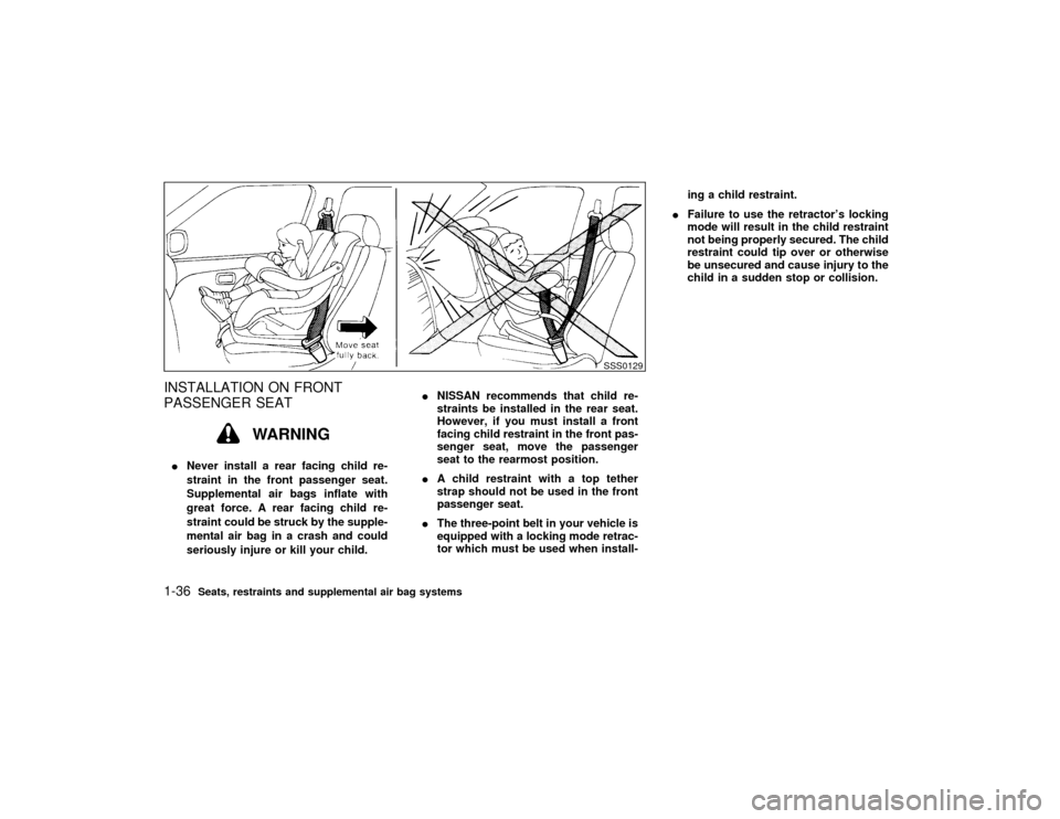
INSTALLATION ON FRONT
PASSENGER SEAT
WARNING
INever install a rear facing child re-
straint in the front passenger seat.
Supplemental air bags inflate with
great force. A rear facing child re-
straint could be struck by the supple-
mental air bag in a crash and could
seriously injure or kill your child.INISSAN recommends that child re-
straints be installed in the rear seat.
However, if you must install a front
facing child restraint in the front pas-
senger seat, move the passenger
seat to the rearmost position.
IA child restraint with a top tether
strap should not be used in the front
passenger seat.
IThe three-point belt in your vehicle is
equipped with a locking mode retrac-
tor which must be used when install-ing a child restraint.
IFailure to use the retractor's locking
mode will result in the child restraint
not being properly secured. The child
restraint could tip over or otherwise
be unsecured and cause injury to the
child in a sudden stop or collision.
SSS0129
1-36
Seats, restraints and supplemental air bag systems
Z
00.1.17/A33-D/V5.0
X
Page 42 of 239

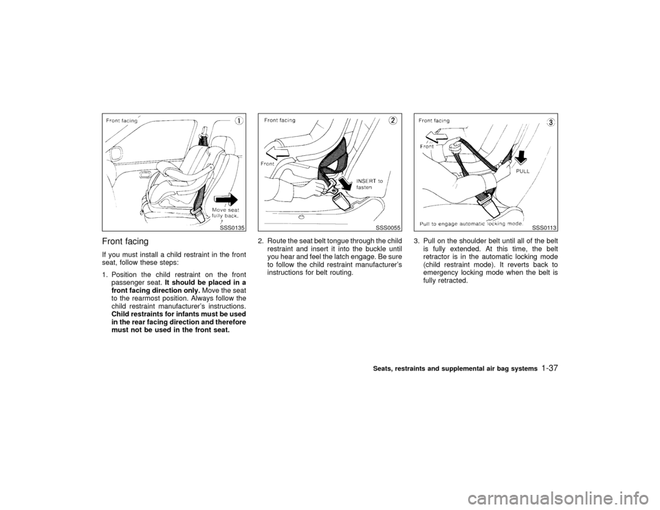
Front facingIf you must install a child restraint in the front
seat, follow these steps:
1. Position the child restraint on the front
passenger seat.It should be placed in a
front facing direction only.Move the seat
to the rearmost position. Always follow the
child restraint manufacturer's instructions.
Child restraints for infants must be used
in the rear facing direction and therefore
must not be used in the front seat.2. Route the seat belt tongue through the child
restraint and insert it into the buckle until
you hear and feel the latch engage. Be sure
to follow the child restraint manufacturer's
instructions for belt routing.3. Pull on the shoulder belt until all of the belt
is fully extended. At this time, the belt
retractor is in the automatic locking mode
(child restraint mode). It reverts back to
emergency locking mode when the belt is
fully retracted.
SSS0135
SSS0055
SSS0113
Seats, restraints and supplemental air bag systems
1-37
Z
00.1.17/A33-D/V5.0
X
Page 43 of 239

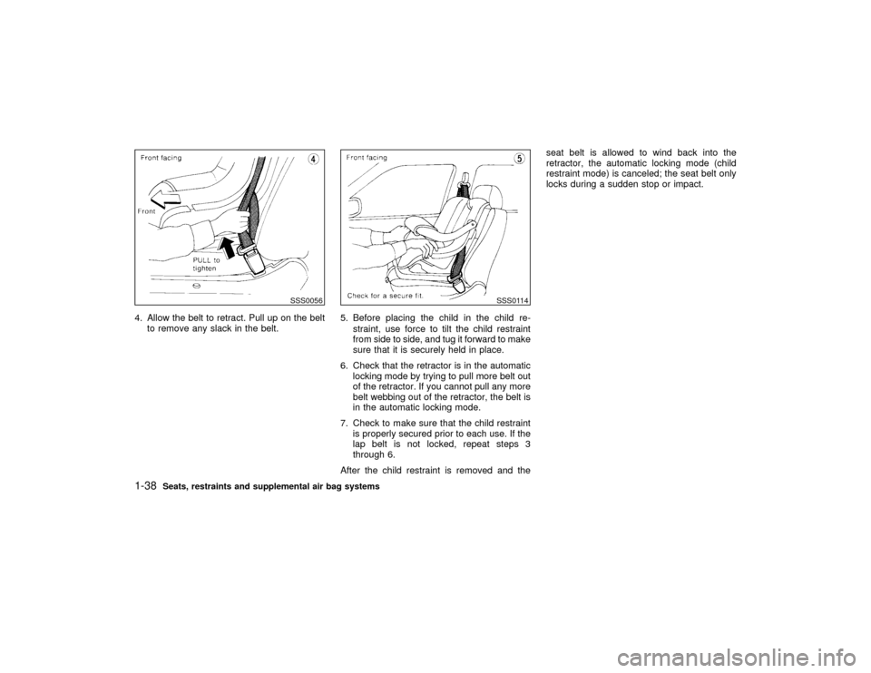
4. Allow the belt to retract. Pull up on the belt
to remove any slack in the belt.5. Before placing the child in the child re-
straint, use force to tilt the child restraint
from side to side, and tug it forward to make
sure that it is securely held in place.
6. Check that the retractor is in the automatic
locking mode by trying to pull more belt out
of the retractor. If you cannot pull any more
belt webbing out of the retractor, the belt is
in the automatic locking mode.
7. Check to make sure that the child restraint
is properly secured prior to each use. If the
lap belt is not locked, repeat steps 3
through 6.
After the child restraint is removed and theseat belt is allowed to wind back into the
retractor, the automatic locking mode (child
restraint mode) is canceled; the seat belt only
locks during a sudden stop or impact.
SSS0056
SSS0114
1-38
Seats, restraints and supplemental air bag systems
Z
00.1.17/A33-D/V5.0
X
Page 44 of 239

MEMO
Seats, restraints and supplemental air bag systems
1-39
Z
00.1.17/A33-D/V5.0
X
Page 45 of 239

2 Instruments and controlsInstrument panel ....................................................... 2-2
Meters and gauges ................................................... 2-3
Speedometer and odometer ..................................... 2-4
Tachometer ............................................................... 2-4
Engine coolant temperature gauge ........................... 2-5
Fuel gauge ................................................................ 2-5
Warning/indicator lights and chimes ......................... 2-7
Checking bulbs.......................................................... 2-7
Warning lights ........................................................... 2-7
Indicator lights ........................................................... 2-9
Chimes .................................................................... 2-11
Security systems ..................................................... 2-12
Theft warning (if so equipped) ................................ 2-12
Nissan Vehicle Immobilizer System ....................... 2-13
Windshield wiper and washer switch ...................... 2-15
Rear window and outside mirror (if so equipped)
defogger switch ....................................................... 2-16
Headlight and turn signal switch ............................. 2-17
Headlight switch ...................................................... 2-17
Turn signal switch ................................................... 2-19
Fog light switch (if so equipped) ............................. 2-19
Hazard warning flasher switch ................................ 2-20
Horn......................................................................... 2-20
Heated seats (if so equipped) ................................. 2-21Traction control system (TCS) cancel switch
(if so equipped) ....................................................... 2-22
Power outlet ............................................................ 2-22
Cigarette lighter and ashtray (accessory) ............... 2-23
Storage .................................................................... 2-23
Trays ....................................................................... 2-23
Glasses case........................................................... 2-24
Cup holder............................................................... 2-24
Glove box ................................................................ 2-25
Console box ............................................................ 2-26
Luggage net (if so equipped) .................................. 2-26
Windows .................................................................. 2-27
Power windows ....................................................... 2-27
Sunroof (if so equipped) ......................................... 2-29
Automatic sunroof ................................................... 2-29
Clock ....................................................................... 2-30
Adjusting the time ................................................... 2-30
Interior light ............................................................. 2-30
Ceiling ..................................................................... 2-30
Personal light .......................................................... 2-31
Vanity mirror light (if so equipped) .......................... 2-32
Trunk light ............................................................... 2-33
Integrated HomeLink
Universal Transceiver
(if so equipped) ....................................................... 2-33
Z
00.1.17/A33-D/V5.0
X
Page 46 of 239

Programming HomeLink
........................................ 2-34
Programming HomeLinkfor Canadian
customers ................................................................ 2-34
Operating the integrated HomeLink
Universal
Transceiver.............................................................. 2-35Programming problem-Diagnosis ............................ 2-35
Clearing the programmed information .................... 2-35
Rolling code programming ...................................... 2-35
Reprogramming a single HomeLink
button .......... 2-36
If your vehicle is stolen ........................................... 2-36
Z
00.1.17/A33-D/V5.0
X
Page 47 of 239

Windshield wiper/washer switch (P.2-15)
Instrument brightness control switch (P.2-18)Meters/gauges (P.2-3)Security indicator light (P.2-12) Cruise control main switch (P.5-14)
Headlight, fog light (if so equipped)
and turn signal switch (P.2-17)
Outside mirror remote control (P.3-13)Fuse box cover (P.8-23)
Tilting steering wheel lock lever (P.3-12) Driver supplemental air bag (P.1-8)
Ignition switch/steering lock (P.5-4) Cruise control set switch (P.5-14)
Power outlet (P.2-22) or cigarette lighter (accessory) (P.2-23)
Hazard warning flasher switch (P.2-20)Ventilator (P.4-2)
Heater/air conditioner control (P.4-3)
Clock (P.2-30)
Radio/cassette player (P.4-14)/CD player (P.4-19) Rear window and outside mirror (if so equipped) defogger switch (P.2-16)
Passenger supplemental air bag (P.1-8)
Glove box (P.2-25)
Tray (P.2-23) or ashtray (accessory) (P.2-23)
SIC1225
See the page indicated in parentheses for operating details.
Traction control system (TCS) cancel switch (if so equipped) (P.2-22)
INSTRUMENT PANEL2-2
Instruments and controls
Z
00.1.17/A33-D/V5.0
X
Page 48 of 239

SIC1321
METERS AND GAUGES
Instruments and controls
2-3
Z
00.1.17/A33-D/V5.0
X
Page 49 of 239

SPEEDOMETER AND ODOMETER
SpeedometerThe speedometer indicates vehicle speed.Odometer/Twin trip odometerThe odometer/twin trip odometer are displayed
when the ignition key is in the ON position.
The odometer records the total distance the
vehicle has been driven.
The twin trip odometer records the distance of
individual trips.Changing the display:
Pushing the reset knob changes the display as
follows:
TRIP A,TRIP B,TRIP A
Resetting the trip odometer:
Pushing the reset knob for more than 1 second
resets the trip odometer to zero.
You can change the display of the trip odom-
eter between A and B and reset them while the
odometers are illuminated for about 30 sec-
onds after the ignition switch has been turned
off.
TACHOMETERThe tachometer indicates engine speed in
revolutions per minute (r/min).
CAUTION
When engine speed approaches the red
zone, shift to a higher gear. Operating
the engine in the red zone may cause
serious engine damage.
SIC1227
SIC1249
2-4
Instruments and controls
Z
00.1.17/A33-D/V5.0
X
Page 50 of 239

ENGINE COOLANT
TEMPERATURE GAUGEThe gauge indicates the engine coolant tem-
perature.
The engine coolant temperature will vary with
the outside air temperature and driving condi-
tions.
CAUTION
If the gauge indicates engine coolant
temperature over the normal range, stop
the vehicle as soon as safely possible. If
the engine is overheated, continued op-
eration of the vehicle may seriously
damage the engine. See ªIf your vehicle
overheatsº in the ª6. In case of emer-
gencyº section for immediate action re-
quired.
FUEL GAUGEThe gauge indicates the approximate fuel level
in the tank.
The gauge may move slightly during braking,
turning, acceleration, or going up or down hill.
The gauge needle is designed to move to the
E (Empty) position when the ignition key is
turned to the OFF position.
Refill the fuel tank before the gauge regis-
ters Empty.
SIC0173
SIC0879
Instruments and controls
2-5
Z
00.1.17/A33-D/V5.0
X