warning lights NISSAN MAXIMA 2003 A33 / 5.G User Guide
[x] Cancel search | Manufacturer: NISSAN, Model Year: 2003, Model line: MAXIMA, Model: NISSAN MAXIMA 2003 A33 / 5.GPages: 247, PDF Size: 2.74 MB
Page 93 of 247

To stop lowering the windows, release the
UNLOCK button.
To start lowering the windows, press the UN-
LOCK button again for 3 more seconds.
This function will operate after the ignition
switch is off and 45 seconds passed or either
the front door is opened.Releasing the trunk lid1. Push the TRUNK button on the keyfob for
longer than 0.5 seconds with the key re-
moved from the ignition key cylinder.
2. The trunk lid opens.
The trunk lid will not open when the trunk lid
cancel lever is in the CANCEL position.
It can be opened only with the key.
See ªTrunk lidº later in this section for cancel
lever.Using the panic alarmIf you are near your vehicle and feel threat-
ened, you may activate the alarm to call atten-
tion as follows:
1. Push the PANIC button on the keyfob for
longer than 0.5 secondswith the key
removed from the ignition key cylinder.
2. The theft warning alarm and headlights willstay on for 30 seconds.
3. The panic alarm stops when:
IIt has run for 30 seconds, or
IThe LOCK or the UNLOCK button is
pressed, or
IThe panic button or the trunk lid release
button is pushed on the keyfob for longer
than 0.5 seconds.
BATTERY REPLACEMENTReplace the battery as follows:
1. Open the lid using a suitable tool.
2. Replace the battery with a new one.
SPA1374
3-8
Pre-driving checks and adjustments
Z
02.7.12/A33-D/V5.0
X
Page 100 of 247
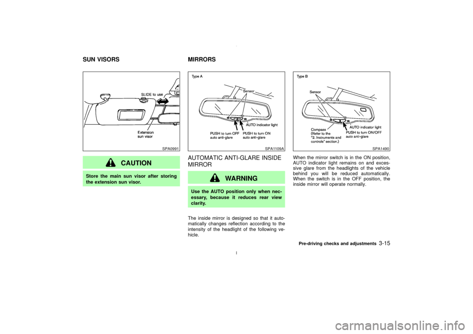
CAUTION
Store the main sun visor after storing
the extension sun visor.
AUTOMATIC ANTI-GLARE INSIDE
MIRROR
WARNING
Use the AUTO position only when nec-
essary, because it reduces rear view
clarity.
The inside mirror is designed so that it auto-
matically changes reflection according to the
intensity of the headlight of the following ve-
hicle.When the mirror switch is in the ON position,
AUTO indicator light remains on and exces-
sive glare from the headlights of the vehicle
behind you will be reduced automatically.
When the switch is in the OFF position, the
inside mirror will operate normally.
SPA0991
SPA1109A
SPA1490
SUN VISORS MIRRORS
Pre-driving checks and adjustments
3-15
Z
02.7.12/A33-D/V5.0
X
Page 142 of 247
IMake sure the area around the vehicle is
clear.
IMaintenance items should be checked pe-
riodically, e.g., each time you check engine
oil.
ICheck that all windows and lights are clean.
IVisually inspect tires for their appearance
and condition. Also, check tires for proper
inflation.
ILock all doors.
IPosition seat and adjust head restraints.
IAdjust inside and outside mirrors.
IFasten seat belts and ask all passengers to
do likewise.
ICheck the operation of warning lights when
key is turned to the ON (3) position.1. Apply the parking brake.
2.Automatic transmission:
Move the selector lever to P (Park) or N
(Neutral). (P preferred.)
The starter is designed not to operate if the
selector lever is in one of the driving posi-
tions.
Manual transmission:
Move the shift lever to N (Neutral) position,
and depress the clutch pedal to the floor
while cranking the engine.
The starter is designed not to operate un-
less the clutch pedal is fully depressed.
3. Crank the enginewith your foot off the
accelerator pedalby turning the ignition
key to START. Release the key when the
engine starts. If the engine starts, but fails
to run, repeat the above procedure.
IWhen the engine is very hard to start in
extremely cold weather or when restarting,
depress the accelerator pedal a little (ap-
proximately 1/5 to the floor) and hold it then
crank the engine. Release the key and the
accelerator pedal when the engine starts.
IWhen the engine is very hard to start
because it is flooded, depress the accelera-tor pedal all the way to the floor and hold it.
Crank the engine for 5 to 6 seconds. After
cranking the engine, release the accelera-
tor pedal. Crank the enginewith your foot
off the accelerator pedalby turning the
ignition key to START. Release the key
when the engine starts. If the engine starts,
but fails to run, repeat the above procedure.
CAUTION
Do not operate the starter for more than
15 seconds at a time. If the engine does
not start, turn the key off and wait 10
seconds before cranking again, other-
wise the starter could be damaged.
4.Warm-up
Allow the engine to idle for at least 30
seconds after starting. Drive at moderate
speed for a short distance first, especially in
cold weather.
BEFORE STARTING THE ENGINE STARTING THE ENGINE
Starting and driving
5-7
Z
02.7.12/A33-D/V5.0
X
Page 143 of 247
AUTOMATIC TRANSMISSION
Gate type shiftThe automatic transmission in your vehicle is
electronically controlled by a transmission con-
trol module to produce maximum power and
smooth operation.
Shown on the following pages are the recom-
mended operating procedures for this trans-
mission. Follow these procedures for maxi-
mum vehicle performance and driving
enjoyment.Starting the vehicleAfter starting the engine, fully depress the foot
brake pedal before shifting the selector lever to
the R (Reverse), N (Neutral), D (Drive), 3, 2 or
1 position. Be sure the vehicle is fully stopped
before attempting to shift the selector lever.
This automatic transmission model is de-
signed so that the foot brake pedal must be
depressed before shifting from P (Park) to
any drive position while the ignition switch
is ON.
The selector lever cannot be moved out of
P (Park) position and into any of the other
gear positions if the ignition key is turned
to the LOCK, OFF or ACC position or if the
key is removed from the switch.1. Keep the foot brake pedal depressed and
shift into a driving gear.
2. Release the parking brake and foot brake,
then gradually start the vehicle in motion.
WARNING
IDo not depress the accelerator pedal
while shifting from P or N to R, D or
manual shift mode. Always depress
the brake pedal until shifting is com-
pleted. Failure to do so could cause
you to lose control and have an acci-
dent.
ICold engine idle speed is high, so use
caution when shifting into a forward
or reverse gear before the engine has
warmed up.
IOn slippery roads, do not downshift.
This may cause a loss of control.
INever shift to P or R while vehicle is
moving. This could cause an acci-
dent.
IIf the selector lever cannot be moved
from the P position while the engineis running and the brake pedal is
depressed, the stoplights may not
work. Malfunctioning stoplights
could cause an accident injuring
yourself and others.
CAUTION
When stopping the vehicle on an uphill
grade, do not hold the vehicle by de-
pressing the accelerator pedal. The foot
brakes should be used for this purpose.
DRIVING THE VEHICLE5-8
Starting and driving
Z
02.7.12/A33-D/V5.0
X
Page 145 of 247
3 (Third gear):
For driving up or down long slopes where
engine braking would be advantageous.
2 (Second gear):
Use for hill climbing or engine braking on
downhill grades.
Do not exceed 68 MPH (110 km/h) in the 2
(Second gear) position.
1 (Low gear):
Use this position when climbing steep hills
slowly or driving slowly through deep snow,
sand or mud, or for maximum engine braking
on steep downhill grades.
Do not exceed 37 MPH (60 km/h) in the 1 (Low
gear) position.
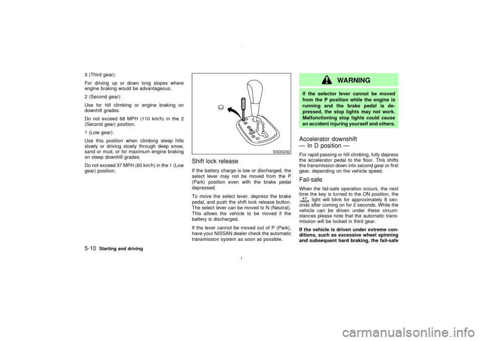
Shift lock releaseIf the battery charge is low or discharged, the
select lever may not be moved from the P
(Park) position even with the brake pedal
depressed.
To move the select lever, depress the brake
pedal, and push the shift lock release button.
The select lever can be moved to N (Neutral).
This allows the vehicle to be moved if the
battery is discharged.
If the lever cannot be moved out of P (Park),
have your NISSAN dealer check the automatic
transmission system as soon as possible.
WARNING
If the selector lever cannot be moved
from the P position while the engine is
running and the brake pedal is de-
pressed, the stop lights may not work.
Malfunctioning stop lights could cause
an accident injuring yourself and others.Accelerator downshift
Ð In D position ÐFor rapid passing or hill climbing, fully depress
the accelerator pedal to the floor. This shifts
the transmission down into second gear or first
gear, depending on the vehicle speed.Fail-safeWhen the fail-safe operation occurs, the next
time the key is turned to the ON position, the
light will blink for approximately 8 sec-
onds after coming on for 2 seconds. While the
vehicle can be driven under these circum-
stances please note that the automatic trans-
mission will be locked in third gear.
If the vehicle is driven under extreme con-
ditions, such as excessive wheel spinning
and subsequent hard braking, the fail-safe
SSD0232
5-10
Starting and driving
Z
02.7.12/A33-D/V5.0
X
Page 154 of 247
conditions are hazardous and extra care is
required while driving.Self-test featureThe anti-lock brake system consists of elec-
tronic sensors, electric pumps, and hydraulic
solenoids controlled by a computer. The com-
puter has a built-in diagnostic feature that tests
the system each time you start the engine and
move the vehicle at a low speed in forward or
reverse. When the self-test occurs, you may
hear a clunk noise and/or feel a pulsation in
the brake pedal. This is normal and is not an
indication of any malfunction. If the computer
senses any malfunction, it switches the anti-
lock brake system OFF and turns on the ABS
warning light in the dashboard. The brake
system will then behave normally, but without
anti-lock assistance.
If the light comes on during the self check, or
while you are driving, you should take your
vehicle to your NISSAN dealer for repair at
your earliest convenience.
WARNING
The anti-lock brake system is a sophis-
ticated device, but it cannot prevent ac-cidents resulting from careless or dan-
gerous driving techniques. It can help
maintain vehicle control during braking
on slippery surfaces, but remember that
the stopping distance on slippery sur-
faces will be longer than on normal
surfaces, even with the anti-lock sys-
tem. Stopping distances may also be
longer on rough, gravel or snow covered
roads, or if you are using tire chains.
Always maintain a safe distance from
the vehicle in front of you. Ultimately,
the responsibility for safety of self and
others rests in the hands of the driver.
Tire type and condition of tires may also
affect braking effectiveness.
IWhen replacing tires, install the
specified size of tires on all four
wheels.
IWhen installing a spare tire, make
sure it is the proper size and type as
specified on the tire placard. See ªVe-
hicle identificationº in the ª9. Techni-
cal and consumer informationº sec-
tion for tire placard location.On slippery surfaces such as wet asphalt
roads, vehicle wheels may spin when the
vehicle is accelerated. This wheel spin re-
duces acceleration, or causes the vehicle to
swerve, thus decreasing vehicle stability.
The traction control system helps limit wheel
spin on slippery roads. The system operates
only if it senses one or both of the front wheels
spinning or beginning to lose traction. When
this happens, the system reduces engine
power and may also upshift the transmission
to help limit wheel spin.
IIndicator light
If a malfunction occurs in the traction con-
trol system, the SLIP and
indicator
lights come on in the meter panel.
As long as these warning lights are on, the
traction control function is canceled. The
vehicle will behaves like a model without
the traction control system.
CAUTION
IThe traction control system is most
effective when the transmission gear
selector is in the D position.
IIf you drive in gear 1 or 2 with the TCSTRACTION CONTROL SYSTEM (if
so equipped)
Starting and driving
5-19
Z
02.7.12/A33-D/V5.0
X
Page 178 of 247

loose nuts. Tighten if necessary.
Tire rotation*:Tires should be rotated every
7,500 miles (12,000 km).
Wheel alignment and balance:If the vehicle
pulls to either side while driving on a straight
and level road, or if you detect uneven or
abnormal tire wear, there may be a need for
wheel alignment.
If the steering wheel or seat vibrates at normal
highway speeds, wheel balancing may be
needed.
For additional information regarding tires, refer
to ªImportant Tire Safety Informationº in the
Warranty Information Booklet (US) or ªTire
Safety Informationº in the Warranty and Road-
side Assistance Information booklet (Canada).
Windshield:Clean the windshield on a regu-
lar basis. Check the windshield at least every
six months for cracks or other damage. Have a
damaged windshield repaired by a qualified
repair facility.
Windshield wiper blades*:Check for cracks
or wear if they do not wipe properly.
Doors and engine hood:Check that all doors
and the engine hood operate smoothly as well
as the trunk lid or back hatch. Also make sure
that all latches lock securely. Lubricate if nec-essary. Make sure that the secondary latch
keeps the hood from opening when the pri-
mary latch is released.
When driving in areas using road salt or other
corrosive materials, check lubrication fre-
quently.
Lights*:Clean the headlights on a regular
basis. Make sure that the headlights, stop
lights, tail lights, turn signal lights, and other
lights are all operating properly and installed
securely. Also check headlight aim.
Inside the vehicleThe maintenance items listed here should be
checked on a regular basis, such as when
performing periodic maintenance, cleaning the
vehicle, etc.
Warning lights and chimes:Make sure that
all warning lights and chimes are operating
properly.
Windshield wiper and washer*:Check that
the wipers and washer operate properly and
that the wipers do not streak.
Windshield defroster:Check that the air
comes out of the defroster outlets properly and
in good quantity when operating the heater or
air conditioner.
Steering wheel:Check for changes in thesteering conditions, such as excessive free
play, hard steering or strange noises.
Seats:Check seat position controls such as
seat adjusters, seatback recliner, etc. to en-
sure they operate smoothly and that all latches
lock securely in every position. Check that the
head restraints move up and down smoothly
and that the locks (if equipped) hold securely
in all latched positions.
Seat belts:Check that all parts of the seat belt
system (for example, buckles, anchors, adjust-
ers and retractors) operate properly and
smoothly, and are installed securely. Check
the belt webbing for cuts, fraying, wear or
damage.
Accelerator pedal:Check the pedal for
smooth operation and make sure the pedal
does not catch or require uneven effort. Keep
the floor mats away from the pedal.
Clutch pedal*:Make sure the pedal operates
smoothly and check that it has the proper free
play.
Brakes:Check that the brakes do not pull the
vehicle to one side when applied.
Brake pedal and booster*:Check the pedal
for smooth operation and make sure it has the
proper distance under it when depressed fully.
Check the brake booster function. Be sure to
Maintenance and do-it-yourself
8-3
Z
02.7.12/A33-D/V5.0
X
Page 202 of 247
HEADLIGHTS
Replacing the xenon headlight bulb
Ð low beam
WARNINGHIGH VOLTAGE
When xenon headlights are on, they
produce a high voltage. To prevent an
electric shock, never attempt to modify
or disassemble. Always have your xe-
non headlights replaced at an autho-
rized NISSAN dealer. For additional in-
formation, see ªHeadlight and turn
signal switchº in the ª2. Instruments and
controlsº section.
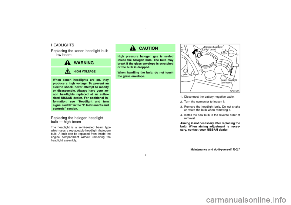
Replacing the halogen headlight
bulb Ð high beamThe headlight is a semi-sealed beam type
which uses a replaceable headlight (halogen)
bulb. A bulb can be replaced from inside the
engine compartment without removing the
headlight assembly.
CAUTION
High pressure halogen gas is sealed
inside the halogen bulb. The bulb may
break if the glass envelope is scratched
or the bulb is dropped.
When handling the bulb, do not touch
the glass envelope.
1. Disconnect the battery negative cable.
2. Turn the connector to loosen it.
3. Remove the headlight bulb. Do not shake
or rotate the bulb when removing it.
4. Install the new bulb in the reverse order of
removal.
Aiming is not necessary after replacing the
bulb. When aiming adjustment is neces-
sary, contact your NISSAN dealer.
SDI1333
Maintenance and do-it-yourself
8-27
Z
02.7.12/A33-D/V5.0
X
Page 232 of 247
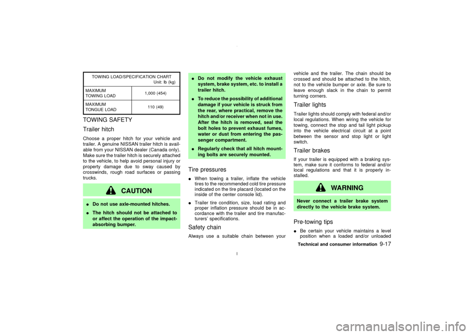
TOWING LOAD/SPECIFICATION CHART
Unit: lb (kg)
MAXIMUM
TOWING LOAD1,000 (454)
MAXIMUM
TONGUE LOAD110 (49)
TOWING SAFETY
Trailer hitchChoose a proper hitch for your vehicle and
trailer. A genuine NISSAN trailer hitch is avail-
able from your NISSAN dealer (Canada only).
Make sure the trailer hitch is securely attached
to the vehicle, to help avoid personal injury or
property damage due to sway caused by
crosswinds, rough road surfaces or passing
trucks.
CAUTION
IDo not use axle-mounted hitches.
IThe hitch should not be attached to
or affect the operation of the impact-
absorbing bumper.IDo not modify the vehicle exhaust
system, brake system, etc. to install a
trailer hitch.
ITo reduce the possibility of additional
damage if your vehicle is struck from
the rear, where practical, remove the
hitch and/or receiver when not in use.
After the hitch is removed, seal the
bolt holes to prevent exhaust fumes,
water or dust from entering the pas-
senger compartment.
IRegularly check that all hitch mount-
ing bolts are securely mounted.
Tire pressuresIWhen towing a trailer, inflate the vehicle
tires to the recommended cold tire pressure
indicated on the tire placard (located on the
inside of the center console lid).
ITrailer tire condition, size, load rating and
proper inflation pressure should be in ac-
cordance with the trailer and tire manufac-
turers' specifications.Safety chainAlways use a suitable chain between yourvehicle and the trailer. The chain should be
crossed and should be attached to the hitch,
not to the vehicle bumper or axle. Be sure to
leave enough slack in the chain to permit
turning corners.
Trailer lightsTrailer lights should comply with federal and/or
local regulations. When wiring the vehicle for
towing, connect the stop and tail light pickup
into the vehicle electrical circuit at a point
between the sensor and stop light or light
switch.Trailer brakesIf your trailer is equipped with a braking sys-
tem, make sure it conforms to federal and/or
local regulations and that it is properly in-
stalled.
WARNING
Never connect a trailer brake system
directly to the vehicle brake system.Pre-towing tipsIBe certain your vehicle maintains a level
position when a loaded and/or unloadedTechnical and consumer information
9-17
Z
02.7.12/A33-D/V5.0
X
Page 242 of 247

Gas cap .......................................................... 3-12
Gauge ............................................................... 2-3
Engine coolant temperature gauge ............. 2-5
Fuel gauge .................................................. 2-5
Odometer..................................................... 2-4
Speedometer ............................................... 2-4
Tachometer ................................................. 2-4
General maintenance ....................................... 8-2
Glove box........................................................ 2-27
Glove box lock ................................................ 2-27
H
Hazard warning flasher switch........................ 2-22
Head restraints ................................................. 1-6
Headlights
Bulb replacement ...................................... 8-27
Headlight switch ........................................ 2-19
Xenon headlights....................................... 2-19
Heated seats................................................... 2-23
Heated steering wheel (if so equipped).......... 2-24
Heater
Engine coolant heater ............................... 5-21
Heater and air conditioner controls ............. 4-3
Heater operation.......................................... 4-3
Heater operation, Semiautomatic air
conditioner ........................................................ 4-4
HomeLink
Universal Transceiver .................. 2-37
Hood, release ................................................. 3-10
Horn ................................................................ 2-22
How to stop alarm, Vehicle security ............... 2-15I
Ignition switch ................................................... 5-4
Automatic transmission models ........... 5-4, 5-8
Key positions ............................................... 5-6
Manual transmission models ............. 5-5, 5-11
Immobilizer system ......................................... 2-15
Indicator lights................................................. 2-12
Inspection/maintenance (I/M) test................... 9-21
Instrument panel ............................................... 2-2
Interior light ..................................................... 2-34
Interior light replacement ................................ 8-28
Interior trunk lid release .................................. 3-12
ISOFIX child restraint ..................................... 1-34
J
Jump starting .................................................... 6-6
K
Keyless entry .................................................... 3-4
Keys .................................................................. 3-2
L
Label, Air conditioner specification label ........ 9-12
Label, Emission control information label ....... 9-11
Label, F.M.V.S.S. certification label................ 9-11
Labels
Air bag warning labels............................... 1-18
Engine serial number ................................ 9-11Vehicle identification number (VIN)........... 9-10
LATCH system................................................ 1-34
License plate, Installing front license plate..... 9-13
Light
Air bag warning light ................................. 1-18
Bulb replacement ...................................... 8-26
Fog light switch ......................................... 2-21
Headlight switch ........................................ 2-19
Headlights Bulb replacement .................... 8-27
Interior light................................................ 2-34
Personal light............................................. 2-35
Replacement ............................................. 8-26
Trunk light.................................................. 2-36
Vanity mirror light ...................................... 2-36
Warning/indicator lights and audible
reminders ........................................... 2-9, 2-12
Xenon headlights....................................... 2-19
Lights, Exterior and interior light
replacement .................................................... 8-28
Loading information (See vehicle loading
information) ..................................................... 9-14
Lock
Door locks ................................................... 3-2
Glove box lock........................................... 2-27
Power door lock .......................................... 3-2
Trunk lid lock opener lever........................ 3-10
Low fuel warning light ..................................... 2-11
M
Maintenance
Battery ....................................................... 8-15
General maintenance .................................. 8-2
Inside the vehicle ........................................ 8-3
Z
02.7.12/A33-D/V5.0
X
10-3