ECU NISSAN MAXIMA 2003 A33 / 5.G Owner's Manual
[x] Cancel search | Manufacturer: NISSAN, Model Year: 2003, Model line: MAXIMA, Model: NISSAN MAXIMA 2003 A33 / 5.GPages: 247, PDF Size: 2.74 MB
Page 60 of 247

comes on. The SECURITY indicator light
glows for about 30 seconds and then blinks.
The system is now activated. If, during this
30 second time period, the door is unlocked
by the key or the keyfob, or the ignition key
is turned to ACC or ON, the system will not
activate.
IIf the key is turned slowly toward the
front of the vehicle when locking the
door, the system may not activate. If the
key is returned beyond the vertical po-
sition toward the rear of the vehicle to
remove the key, the system may be
deactivated. If the indicator light fails to
glow for 30 seconds, unlock the door
once and lock it again.
IEven when the driver and/or passengers
are in the vehicle, the system will acti-
vate with all doors, hood and trunk lid
locked and ignition key off. Turn the
ignition key to ACC to turn the system
off.
Vehicle security system operationThe security system will give the following
alarm:
IThe headlights blink and the horn sounds
intermittently.
IThe alarm automatically turns off after ap-proximately 1 minute. However, the alarm
reactivates if the vehicle is tampered with
again. The alarm can be shut off by unlock-
ing a door or trunk lid with the key, or by
pressing the UNLOCK button on the key-
fob.
The alarm is activated by:
IOpening the door without using the key or
keyfob.
IOpening the trunk lid without using the key
or keyfob.
IOpening the hood.
How to stop alarmThe alarm will stop only by unlocking a door or
trunk lid with the key, or by pressing the
UNLOCK button on keyfob. The alarm will not
stop if the ignition switch is turned to ACC or
ON.
If the system does not operate as de-
scribed above, have it checked by your
NISSAN dealer.NISSAN VEHICLE IMMOBILIZER
SYSTEMThe Nissan Vehicle Immobilizer System will
not allow the engine to start without the use ofthe registered Nissan Vehicle Immobilizer Sys-
tem key.
If the engine fails to start using the registered
Nissan Vehicle Immobilizer System key, it may
be due to interference caused by another
Nissan Vehicle Immobilizer System key, an
automated toll road device or automated pay-
ment device on the key ring. Restart the en-
gine using the following procedures:
1. Leave the ignition switch in the ON position
for approximately 5 seconds.
2. Turn the ignition switch to the OFF or LOCK
position and wait approximately 10 sec-
onds.
3. Repeat step 1 and 2 again.
4. Restart the engine while holding the device
(which may have caused the interference)
separate from the registered Nissan Ve-
hicle Immobilizer System key.
If this procedure allows the engine to start,
NISSAN recommends placing the regis-
tered Nissan Vehicle Immobilizer System
key on a separate key ring to avoid inter-
ference from other devices.
Statement related to section 15 of FCC
rules for Nissan Vehicle Immobilizer Sys-
Instruments and controls
2-15
Z
02.7.12/A33-D/V5.0
X
Page 61 of 247

tem (CONT ASSY-IMMOBILIZER, ANT
ASSY-IMMOBILIZER)
This device complies with part 15 of the
FCC Rules and RSS-210 of Industry
Canada. Operation is subject to the follow-
ing two conditions;
(1) This device may not cause harmful
interference, and (2) this device must ac-
cept any interference received, including
interference that may cause undesired op-
eration of the device.
CHANGES OR MODIFICATIONS NOT EX-
PRESSLY APPROVED BY THE MANUFAC-
TURE FOR COMPLIANCE COULD VOID
THE USER'S AUTHORITY TO OPERATE
THE EQUIPMENT.
Security indicator lightIf Nissan Vehicle Immobilizer System is mal-
functioning, this light will remain on while the
ignition key is in the ON position.
If the light still remains on and/or the en-
gine will not start, see your NISSAN dealer
for Nissan Vehicle Immobilizer System ser-
vice as soon as possible. Please bring all
Nissan Vehicle Immobilizer System keys
that you have when visiting your NISSAN
dealer for service.The windshield wiper and washer operates
when the ignition key is in the ON position.
Push the lever down to operate the wiper.
Intermittent operation can be adjusted from 2
to 13 seconds by turning the knob.
Pull the lever toward you to operate the
washer. The wipers will automatically operate
several times when the washer is activated.
Push the lever up to cycle the wipers one time.
SIC1228
SIC1739
WINDSHIELD WIPER AND
WASHER SWITCH
2-16
Instruments and controls
Z
02.7.12/A33-D/V5.0
X
Page 74 of 247

WARNING
IProperly secure all cargo to help pre-
vent it from sliding or shifting.
IBe sure to secure hooks into the
retainers. The cargo restrained in the
net must not exceed 30 lb (13.6 kg) or
the net may not stay secured.
POWER WINDOWS
WARNING
IMake sure that all passengers have
their hands, etc. inside the vehicle
while it is in motion and before clos-
ing the windows. Use the window
lock switch to prevent unexpected
use of the power windows.
IDo not leave children unattended in-
side the vehicle. They could unknow-ingly activate switches or controls
and become trapped in a window.
Unattended children could become
involved in serious accidents.
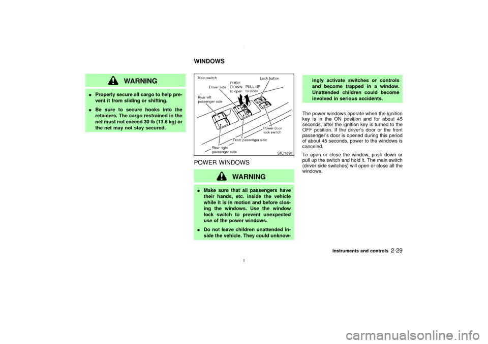
The power windows operate when the ignition
key is in the ON position and for about 45
seconds, after the ignition key is turned to the
OFF position. If the driver's door or the front
passenger's door is opened during this period
of about 45 seconds, power to the windows is
canceled.
To open or close the window, push down or
pull up the switch and hold it. The main switch
(driver side switches) will open or close all the
windows.
SIC1891
WINDOWS
Instruments and controls
2-29
Z
02.7.12/A33-D/V5.0
X
Page 82 of 247

The HomeLink
Universal Transceiver pro-
vides a convenient way to consolidate the
functions of up to three individual hand-held
transmitters into one built-in device.
The HomeLinkUniversal Transceiver power
will automatically turn off 30 minutes after the
ignition switch has been turned to the off
position.
HomeLink
Universal Transceiver:
IWill operate most Radio Frequency (RF)
devices such as garage doors, gates, home
and office lighting, entry door locks and
security systems.
IIs powered by your vehicle's battery. No
separate batteries are required. If the vehi-
cle's battery is discharged or is discon-
nected, HomeLink
will retain all program-
ming.
Once the HomeLinkUniversal Transceiver
is programmed, retain the original trans-
mitter for future programming procedures
(i.e., new vehicle purchases). Upon sale of
the vehicle, the programmed HomeLink
Universal Transceiver buttons should be
erased for security purposes. For addi-
tional information, refer to ªProgramming
HomeLink
º later in this section.
WARNING
IDo not use the HomeLink
Universal
Transceiver with any garage door
opener that lacks safety stop and
reverse features as required by fed-
eral safety standards. (These stan-
dards became effective for opener
models manufactured after April 1,
1982). A garage door opener which
cannot detect an object in the path of
a closing garage door and then auto-
matically stop and reverse, does not
meet current federal safety stan-
dards. Using a garage door opener
without these features increases the
risk of serious injury or death.
IDuring programming, your garage
door or gate may open or close. Make
sure that people and objects are clear
of the garage door or gate that you
are programming.
IYour vehicle's engine should be
turned off while programming theHomeLink
Universal Transceiver.
PROGRAMMING HomeLinkTo program your HomeLink Transceiver to
operate a garage door, gate, or entry door
opener, home or office lighting, you need to be
at the same location as the device. Note:
Garage door openers (manufactured after
1996) have ªrolling code protectionº. To pro-
gram a garage door opener equipped with
ªrolling code protectionº; you will need to use a
ladder to get up to the garage door opener
motor to be able to access the ªsmart or learnº
program button.
HomeLink
UNIVERSAL
TRANSCEIVER (if so equipped)
Instruments and controls
2-37
Z
02.7.12/A33-D/V5.0
X
Page 94 of 247

Recommended battery: Sanyo CR2025 or
equivalent
Make sure that theÅside faces the
bottom case.
3. Close the lid securely.
4. Push the keyfob button two or three times
to check its operation.
See your NISSAN dealer if you need any
assistance for replacement.
If the battery is removed for any reason
other than replacement, perform step 4
above.
IBe careful not to touch a circuit board
and a battery terminal.
IAn improperly disposed battery can
harm the environment. Always confirm
local regulations for battery disposal.
IThe keyfob is water-resistant; however,
if it does get wet, immediately wipe com-
pletely dry.
IWhen changing batteries, do not let dust
or oil get on the keyfob.
FCC Notice:
Changes or modifications not expressly
approved by the manufacturer compliancecould void the user's authority to operate
the equipment. This device complies with
Part 15 of the FCC Rules and RSS-210 of
Industry Canada. Operation is subject to
the following two conditions: (1) This de-
vice may not cause harmful interference,
and (2) this device must accept any inter-
ference received, including interference
that may cause undesired operation of the
device.
Pre-driving checks and adjustments
3-9
Z
02.7.12/A33-D/V5.0
X
Page 96 of 247

OPENER OPERATIONThe trunk lid release button is located under
the driver's arm rest.
To open the trunk lid, pull the release button.
To close, push the trunk lid down securely.
Cancel leverWhen the lever is in the cancel position, the
trunk lid cannot be opened with the trunk lid
release button. It can be opened only with the
master key.
KEY OPERATIONTo open the trunk lid, turn the key clockwise.
To close, lower and push the trunk lid down
securely.
SPA0985
SPA0095
SPA0992
Pre-driving checks and adjustments
3-11
Z
02.7.12/A33-D/V5.0
X
Page 97 of 247

INTERIOR TRUNK LID RELEASE
WARNING
Closely supervise children when they
are around cars to prevent them from
playing and becoming locked in the
trunk where they could be seriously in-
jured. Keep the car locked, with the
trunk closed, when not in use, and pre-
vent children's access to car keys.
The interior trunk lid release mechanism pro-vides a means of escape for children and
adults in the event they become locked inside
the trunk.
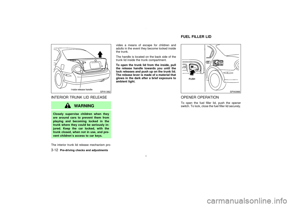
The handle is located on the back side of the
trunk lid inside the trunk compartment.
To open the trunk lid from the inside, pull
the release handle towards you until the
lock releases and push up on the trunk lid.
The release lever is made of a material that
glows in the dark after a brief exposure to
ambient light.
OPENER OPERATIONTo open the fuel filler lid, push the opener
switch. To lock, close the fuel filler lid securely.
SPA1382
SPA0986
FUEL FILLER LID
3-12
Pre-driving checks and adjustments
Z
02.7.12/A33-D/V5.0
X
Page 102 of 247

AUTOMATIC SEAT POSITIONER
OPERATION (A/T models only)This system is designed so that the driver's
seat will automatically move when the auto-
matic transmission selector lever is in the P
(Park) position. This allows the driver to get in
and out of the driver's seat more easily.
When one of the following conditions is met,
the driver's seat will slide backward:
IWhen the key is removed from the ignition
switch.
IWhen the driver's door is opened with the
key turned to ACC or LOCK.
IWhen the key is turned from ON to ACC
with the driver's door open.
When one of the following conditions is met,
the driver's seat will return to the positions
before being set.
IWhen the key is inserted into the ignition
switch.
IWhen the driver's door is closed with the
key turned to LOCK.
PROCEDURE FOR STORING
MEMORYTwo positions can be stored in the automatic
driver's seat positioner memory.Follow these
procedures to use the memory system.
1. A/T models:
Set the automatic transmission selector
lever to the P (Park) position.
M/T models:
Apply the parking brake securely when the
vehicle is stopped.
2. Turn the ignition ON.
3. Adjust the driver's seat and steering column
to the desired positions by manually oper-
ating each adjusting switch. For additional
information, see ªSeatsº in the ª1. Seats,
restraints and supplemental air bag sys-
temsº section and ªSteering wheelº earlier
in this section.
SPA1385
AUTOMATIC SEAT POSITIONER
(if so equipped)
Pre-driving checks and adjustments
3-17
Z
02.7.12/A33-D/V5.0
X
Page 103 of 247

During this step, do not turn the ignition to
any positions other than ON.
4. Push the SET switch and, within 5 seconds,
push the memory switch 1 or 2 fully for at
least 1 second.
The indicator light for the pushed memory
switch will come on and stay on for approxi-
mately 5 seconds after pushing the switch.
After the indicator light goes off, the se-
lected positions are stored in the selected
memory (1 or 2).
If memory is stored in the same memory
switch, the previous memory will be de-
leted.
Confirming memory storageITurn the ignition ON and push the SET
switch. If the main memory has not been
stored, the indicator light will come on for
approximately 0.5 seconds. When the
memory has stored the position, the indica-
tor light will stay on for approximately 5
seconds.
IIf the battery cable is disconnected, or if the
fuse blows, the memory will be canceled. In
such a case, reset the desired positions
using the following procedures.
1. Open and close the driver's door more thantwo times with the ignition key in the LOCK
position.
2. Reset the desired position using the previ-
ous procedure.
Selecting the memorized position1. A/T models:
Set the automatic transmission selector le-
ver to the P (Park) position.
M/T models:
Apply the parking brake securely when the
vehicle is stopped.
2. Turn the ignition ON.
3. Push the memory switch 1 or 2 fully for at
least 1 second.
The driver's seat will move to the memo-
rized position with the indicator light flash-
ing. Then the light will stay on for approxi-
mately 5 seconds.
When memory switch 1 or 2 is pushed with the
driver's door open and then the key inserted
into the ignition switch within approximately 1
minute, the driver's seat will move to the
memorized position. Ð A/T models only
System operationThe automatic drive positioner system will not
work or will stop operating under the following
conditions:
Iwhen the vehicle speed is above 4 MPH (7
km/h).
Iwhen any two or more of the memory
switches are simultaneously pressed while
the automatic drive positioner is operating.
Iwhen the adjusting switch for the driver's
seat is turned on while the automatic drive
positioner is operating.
Iwhen the cancel switch located on the
instrument panel is pushed to cancel.
Iwhen the memory switch 1 or 2 is not
pushed for at least 1 second.
Iwhen the seat has already been moved to
the memorized position.
Iwhen no seat position is stored in the
memory switch.
Iwhen the parking brake is not applied. Ð
M/T models
Iwhen the vehicle speed is above 4 MPH (7
km/h) while the parking brake is applied. Ð
M/T models
To restart the drive positioner system,
3-18
Pre-driving checks and adjustments
Z
02.7.12/A33-D/V5.0
X
Page 156 of 247

chains, make sure they are of proper size
for the tires on your vehicle and are in-
stalled according to the chain manufactur-
er's suggestions.Use only SAE Class S
chains.Other types may damage your
vehicle. Use chain tensioners when recom-
mended by the tire chain manufacturer to
ensure a tight fit. Loose end links of the tire
chain must be secured or removed to pre-
vent the possibility of whipping action dam-
age to the fenders or underbody. If pos-
sible, avoid fully loading your vehicle when
using tire chains. In addition, drive at a
reduced speed. Otherwise, your vehicle
may be damaged and/or vehicle handling
and performance may be adversely af-
fected.
Never install tire chains on a T-type spare
tire. Do not use tire chains on dry roads.
SPECIAL WINTER EQUIPMENTIt is recommended that the following items be
carried in the vehicle during winter:
Ia scraper and stiff-bristled brush to remove
ice and snow from the windows and wiper
blades.
Ia sturdy, flat board to be placed under the
jack to give it firm support.Ia shovel to dig the vehicle out of snow-
drifts.
Iextra window washer fluid to refill the res-
ervoir tank.
DRIVING ON SNOW OR ICE
WARNING
IWet ice (32ÉF, 0ÉC and freezing rain),
very cold snow or ice can be slick and
very hard to drive on. The vehicle will
have a lot less traction or grip under
these conditions. Try to avoid driving
on wet ice until the road is salted or
sanded.
IWhatever the condition, drive with
caution. Accelerate and slow down
with care. If accelerating or down-
shifting too fast, the drive wheels will
lose even more traction.
IAllow more stopping distance under
these conditions. Braking should be
started sooner than on dry pavement.
IAllow greater following distances on
slippery roads.IWatch for slippery spots (glare ice).
These may appear on an otherwise
clear road in shaded areas. If a patch
of ice is seen ahead, brake before
reaching it. Try not to brake while
actually on the ice, and avoid any
sudden steering maneuvers.
IDo not use cruise control on slippery
roads.
ISnow can trap dangerous exhaust
gases under your vehicle. Keep snow
clear of the exhaust pipe and from
around your vehicle.
ENGINE BLOCK HEATER (if so
equipped)An engine block heater to assist extreme cold
temperature starting is available through your
NISSAN dealer.
WARNING
Do not use your heater with an un-
grounded electrical system or two-
Starting and driving
5-21
Z
02.7.12/A33-D/V5.0
X