ECO mode NISSAN MAXIMA 2003 A33 / 5.G Owners Manual
[x] Cancel search | Manufacturer: NISSAN, Model Year: 2003, Model line: MAXIMA, Model: NISSAN MAXIMA 2003 A33 / 5.GPages: 247, PDF Size: 2.74 MB
Page 2 of 247
IMPORTANT INFORMATION
ABOUT THIS MANUALYou will see various symbols in this manual.
They are used in the following ways:
WARNING
This is used to indicate the presence of a
hazard that could cause death or serious
personal injury. To avoid or reduce the
risk, the procedures must be followed
precisely.
CAUTION
This is used to indicate the presence of a
hazard that could cause minor or moder-
ate personal injury or damage to your
vehicle. To avoid or reduce the risk, the
procedures must be followed carefully.If you see this symbol, it meansDo not do
thisorDo not let this happen.
CALIFORNIA PROPOSITION 65
WARNING
WARNING
Engine Exhaust, some of its constitu-
ents, and certain vehicle components
contain or emit chemicals known to State
of California to cause cancer and birth
defects or other reproductive harm.
2002 NISSAN MOTOR CO., LTD.
TOKYO, JAPANAll rights reserved. No part of this Owner's Manual may
be reproduced or stored in a retrieval system, or trans-
mitted in any form, or by any means, electronic, me-
chanical, photocopying, recording or otherwise, without
the prior written permission of Nissan Motor Co., Ltd.
SIC0697Z
02.7.12/A33-D/V5.0
X
Page 41 of 247
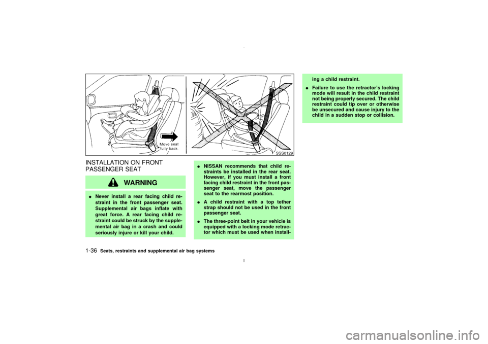
INSTALLATION ON FRONT
PASSENGER SEAT
WARNING
INever install a rear facing child re-
straint in the front passenger seat.
Supplemental air bags inflate with
great force. A rear facing child re-
straint could be struck by the supple-
mental air bag in a crash and could
seriously injure or kill your child.INISSAN recommends that child re-
straints be installed in the rear seat.
However, if you must install a front
facing child restraint in the front pas-
senger seat, move the passenger
seat to the rearmost position.
IA child restraint with a top tether
strap should not be used in the front
passenger seat.
IThe three-point belt in your vehicle is
equipped with a locking mode retrac-
tor which must be used when install-ing a child restraint.
IFailure to use the retractor's locking
mode will result in the child restraint
not being properly secured. The child
restraint could tip over or otherwise
be unsecured and cause injury to the
child in a sudden stop or collision.
SSS0129
1-36
Seats, restraints and supplemental air bag systems
Z
02.7.12/A33-D/V5.0
X
Page 52 of 247

Zone variation change procedureThe difference between magnetic north and
geographical north is known as variance. In
some areas, this difference can sometimes be
great enough to cause false compass read-
ings. Follow these instructions to set the vari-
ance for your particular location if this hap-
pens:
1. Press the COMPASS switch for more than
3 seconds. The current zone number will
appear in the display.
2. Find your current location and variance one
number on the zone map.
3. Press the COMPASS switch until the new
zone number appears in the display. After
you stop pressing the switch in, the display
will show a compass direction within a few
seconds.
Inaccurate compass direction:
1. With the display turned on, push the COM-
PASS switch for 3 seconds, until the zone
selection comes up (a number will be dis-
played in the mirror compass window).
2. Toggle until correct zone is found and re-
lease switch.
3. The display will show all segments, and
return to the normal compass mode within
SIC0611
Instruments and controls
2-7
Z
02.7.12/A33-D/V5.0
X
Page 54 of 247

or
Anti-lock brake warning light
Low washer fluid warning light
High beam indicator light (Blue)
A/T check warning light (A/T models)
Seat belt warning light
Malfunction indicator lamp (MIL)
or
Brake warning light
Stop/tail warning light
Slip indicator light
Charge warning light
Supplemental air bag warning light
Traction control system indicator light
Door open warning light
Trunk lid open warning light
Turn signal/hazard indicator lights
Engine oil pressure warning light
Cruise main switch indicator light
Low fuel warning light
Cruise set indicator light
CHECKING BULBSApply the parking brake and turn the ignition
key to ON without starting the engine. The
following lights will come on:
,
or
,
,
The following lights come on briefly and then
go off:
,
or
,
,
,
If any light fails to come on, it may indicate a
burned-out bulb or an open circuit in the elec-trical system. Have the system repaired
promptly.
WARNING LIGHTS
or
Anti-lock brake
warning light
After turning the ignition key to the ON posi-
tion, the light will illuminate. The light will turn
off after about 2 seconds if the system is
operational.
If the light comes on while the engine isrunning, it may indicate that the anti-lock brake
system is not functioning properly. Have the
system checked by your NISSAN dealer.
If an abnormality occurs in the system, the
anti-lock function will cease but the ordinary
brakes will continue to operate normally.
If the light comes on while you are driving,
contact your NISSAN dealer for repair.
WARNING/INDICATOR LIGHTS
AND AUDIBLE REMINDERS
Instruments and controls
2-9
Z
02.7.12/A33-D/V5.0
X
Page 55 of 247
A/T check warning light (A/T
models)
When the ignition switch is turned ON, the light
comes on for 2 seconds. If the light blinks for
approximately 8 seconds, it may indicate the
automatic transmission system is not function-
ing properly. Have your NISSAN dealer check
and repair the transmission.
or
Brake warning light
This light functions for both the parking brake
and the foot brake systems.
Parking brake indicator:
When the ignition key is in the ON position, the
light comes on when the parking brake is
applied.
Low brake fluid warning light:
The light warns of a low brake fluid level. If the
light comes on while the engine is running with
the parking brake not applied, stop the vehicle
and perform the following:
1. Check the brake fluid level. Add brake fluid
as necessary. See ªBrake and clutch fluidº
in the ª8. Maintenance and do-it-yourselfº
section.
WARNING
IYour brake system may not be work-
ing properly if the warning light is on.
Driving could be dangerous. If you
judge it to be safe, drive carefully to
the nearest service station for re-
pairs. Otherwise, have your vehicle
towed because driving it could be
dangerous.
IPressing the brake pedal with the
engine stopped and/or low brake fluid
level may increase your stopping dis-
tance and braking will require greater
pedal effort as well as greater pedal
travel.
IIf the brake fluid level is below the
MIN mark on the brake fluid reservoir,
do not drive until the brake system
has been checked at a NISSAN
dealer.
2. If the brake fluid level is correct, have the
warning system checked by a NISSAN
dealer.
Charge warning light
If the light comes on while the engine is
running, it may indicate that the charging sys-
tem is not functioning properly. Turn the en-
gine off and check the alternator belt. If the belt
is loose, broken, missing or if the light remains
on, see your NISSAN dealer immediately.
CAUTION
Do not continue driving if the belt is
loose, broken or missing.
Door open warning light
This light comes on when any of the doors are
not closed securely while the ignition key is
ON.
Engine oil pressure warning
light
This light warns of low engine oil pressure. If
the light flickers or comes on during normal
driving, pull off the road in a safe area, stop the
engineimmediatelyand call a NISSAN dealer
or other authorized repair shop.
The oil pressure warning light is not de-
signed to indicate a low oil level. Use the
dipstick to check the oil level.See ªEngine
2-10
Instruments and controls
Z
02.7.12/A33-D/V5.0
X
Page 77 of 247
sunroof is opened. However, it must be closed
manually.
WARNING
IIn an accident you could be thrown
from the vehicle through an open
sunroof. Always use seat belts and
child restraints.
IDo not allow anyone to stand up or
extend any portion of their body out
of the opening while the vehicle is in
motion or while the sunroof is clos-
ing.
CAUTION
IRemove water drops, snow, ice or
sand from the sunroof before open-
ing.
IDo not place any heavy object on the
sunroof or surrounding area.If the sunroof does not closeHave your NISSAN dealer check and repair
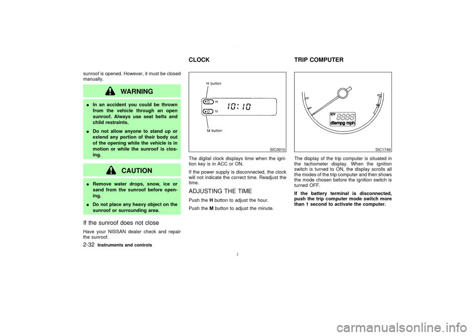
the sunroof.The digital clock displays time when the igni-
tion key is in ACC or ON.
If the power supply is disconnected, the clock
will not indicate the correct time. Readjust the
time.
ADJUSTING THE TIMEPush theHbutton to adjust the hour.
Push theMbutton to adjust the minute.The display of the trip computer is situated in
the tachometer display. When the ignition
switch is turned to ON, the display scrolls all
the modes of the trip computer and then shows
the mode chosen before the ignition switch is
turned OFF.
If the battery terminal is disconnected,
push the trip computer mode switch more
than 1 second to activate the computer.
SIC0910
SIC1749
CLOCK TRIP COMPUTER
2-32
Instruments and controls
Z
02.7.12/A33-D/V5.0
X
Page 78 of 247

When the ignition switch is turned to ON,
modes of the trip computer can be selected by
pushing once on the trip mode switch. The
following modes can be selected:Outside air temperature (ICY Ð ÉF
or ÉC)The outside air temperature is displayed in ÉF
or ÉC.
The outside air temperature mode includes a
low temperature warning feature: below 37ÉF
(3ÉC), the outside air temperature mode is
automatically selected and ICY indicator will
illuminate in order to draw the driver's atten-tion. Press the mode switch if you wish to
return to the mode that was selected before
the warning occurred. The ICY indicator will
continue blinking as long as the temperature
remains below 39ÉF (4ÉC).
Distance to empty (dte Ð mile or
km)The distance to empty (dte) mode provides
you with an estimation of the distance that can
be driven before refueling. The dte is con-
stantly being calculated, based on the amount
of fuel in the fuel tank and the actual fuel
consumption.
The display is updated every 30 seconds.
The dte mode includes a low range warning
feature: when the fuel level is low, the dte
mode is automatically selected and the digits
blink in order to draw the driver's attention.
Press the mode switch if you wish to return to
the mode that was selected before the warning
occurred. The dte mark (dte) will remain blink-
ing until the vehicle is refuelled.
When the fuel level drops even lower, the dte
display will change to (
).
NOTE:
IIf the amount of fuel added while the
ignition switch is OFF is small, the dis-play just before the ignition switch is
turned OFF may continue to be dis-
played.
IWhen driving uphill or rounding curves,
the fuel in the tank shifts, which may
momentarily change the display.
Average fuel consumption
(
or
)
The Average fuel consumption mode shows
the average fuel consumption since the last
reset. Resetting is done by pressing the mode
switch for more than approximately 1 second.
The display is updated every 30 seconds. At
about the first 1/3 miles (500 m) after a reset,
the display shows (
).
Average speed (
or
)
The average speed mode shows the average
vehicle speed since last reset. Resetting is
done by pressing the mode switch for more
than approximately 1 second. The display is
updated every 30 seconds. The first 30 sec-
onds after a reset, the display shows (
).
Journey timeThe journey time mode shows the time since
the last reset. The displayed time can be reset
by pressing the mode switch for more than
approximately 1 second.
SIC1750
Instruments and controls
2-33
Z
02.7.12/A33-D/V5.0
X
Page 79 of 247

NOTE:
If a low temperature warning and low range
warning occur simultaneously, other dis-
play modes switch automatically to the
outside temperature display.
When the mode switch is pushed, the dis-
play switches to the mode chosen before
the warning display, and the ICY indicator
will blink.
CEILINGThe ceiling light has a three-position switch.
When the switch is in the centerqposition, the
light will illuminate when a door is opened.
The light will stay on for about 30 seconds
when:
IThe doors are unlocked by the keyfob, a
key or the lock-unlock switch while all doors
are closed.
IThe driver's door is opened and then closed
while the key is removed from the ignition
switch.IThe key is removed from the ignition switch
while all doors are closed.
The ceiling light will turn off while the 30
second timer is activated, when:
IThe driver's door is locked either with the
keyfob, a key, or the lock-unlock switch.
IThe ignition switch is turned ON.
When the interior light switch or personal
light switch is in the ON position, the inte-
rior, personal, and vanity mirror lights will
automatically turn off 30 minutes after the
ignition switch has been turned to the OFF
position. To turn on the light again, insert
the key into the ignition switch and move it
to the ON position.
After the above procedure, the interior, per-
sonal, and vanity mirror lights will automati-
cally turn off 30 minutes after the latest opera-
tion of the following with the ignition switch in
the ACC or OFF position:
IOpening or closing any door
ILocking or unlocking with the keyfob, a key
or the lock-unlock switch.
IInserting or removing a key from the ignition
switch
These lights will turn on again when any of the
IC1226
INTERIOR LIGHT
2-34
Instruments and controls
Z
02.7.12/A33-D/V5.0
X
Page 83 of 247

1. To begin, press and hold the 2 outer
HomeLink
buttons (to clear the memory)
until the indicator light blinks slowly (after
20 seconds). Release both buttons.
2. Position the end of the hand-held transmit-
ter 1-3 inches away from the HomeLink
surface.3. Using both hands, simultaneously press
and hold both the HomeLink
button you
want to program and the hand-held trans-
mitter button.
DO NOT release the buttons until step 4
has been completed.
4. Hold down both buttons until the indicator
light on the HomeLink
flashes, changing
from a ªslow blinkº to a ªrapidly flashing
blinkº. This could take up to 90 seconds.
When the indicator light flashes rapidly,
both buttons may be released. The rapidly
flashing light indicates successful program-
ming. To activate the garage door or other
programmed device, press and hold theprogrammed HomeLink
button - releasing
when the device begins to activate.
5. If the indicator light on the HomeLink
blinks rapidly for two seconds and then
turns solid, HomeLink
has picked up a
ªrolling codeº garage door opener signal.
You will need to proceed with the next steps
to train the HomeLinkto complete the
programming which may require a ladder
and another person for convenience.
6. Press and release the ªsmartº or ªlearnº
program button located on the garage door
opener's motor to activate the ªtraining
modeº. This button is usually located near
the antenna wire that hangs down from the
motor. If the wire originates from under a
light lens, you will need to remove the lens
to access the program button.
NOTE:
Once you have pressed and released the
program button on the garage door open-
er's motor and the ªtraining lightº is lit, you
have 30 seconds in which to perform step
7. Use the help of a second person for
convenience to assist when performing
this step.
7. Quickly within 30 seconds of pressing and
releasing the garage door opener program
SIC2019
SIC2020
2-38
Instruments and controls
Z
02.7.12/A33-D/V5.0
X
Page 90 of 247
IDo not drop the keyfob.
IDo not strike the keyfob sharply
against another object.
IDo not place the keyfob for an ex-
tended period in an area where tem-
peratures exceed 140ÉF (60ÉC).
If a keyfob is lost or stolen, NISSAN
recommends erasing the ID code of that
keyfob. This will prevent the keyfob from
unauthorized use to unlock the vehicle.
For information regarding the erasing
procedure, please contact an authorized
NISSAN dealer.HOW TO USE REMOTE KEYLESS
ENTRY SYSTEM
Setting hazard indicator and horn
modeThis vehicle is set in hazard indicator and horn
mode when you first receive the vehicle.
In hazard indicator and horn mode, when the
LOCK button is pushed, the hazard indicator
flashes twice and the horn chirps once. Whenthe UNLOCK button is pushed, the hazard
indicator flashes once.
If hazard indicator and horn mode is not nec-
essary, you can switch to hazard indicator only
mode by following the switching procedure.
In hazard indicator only mode, when the LOCK
button is pushed, the hazard indicator flashes
twice. When the UNLOCK button is pushed,
neither the hazard indicator nor the horn oper-
ates.
(Switching procedure)
Push the LOCK and UNLOCK buttons on the
keyfob simultaneously for more than 2 sec-
onds to switch from one mode to the other.
When pushing the buttons to set hazard indi-
cator only mode, the hazard indicator flashes 3
times.
When pushing the buttons to set hazard indi-
cator and horn mode, the hazard indicator
flashes once and the horn chirps once.
Pre-driving checks and adjustments
3-5
Z
02.7.12/A33-D/V5.0
X