check engine NISSAN MAXIMA 2006 A34 / 6.G User Guide
[x] Cancel search | Manufacturer: NISSAN, Model Year: 2006, Model line: MAXIMA, Model: NISSAN MAXIMA 2006 A34 / 6.GPages: 312, PDF Size: 4.88 MB
Page 94 of 312
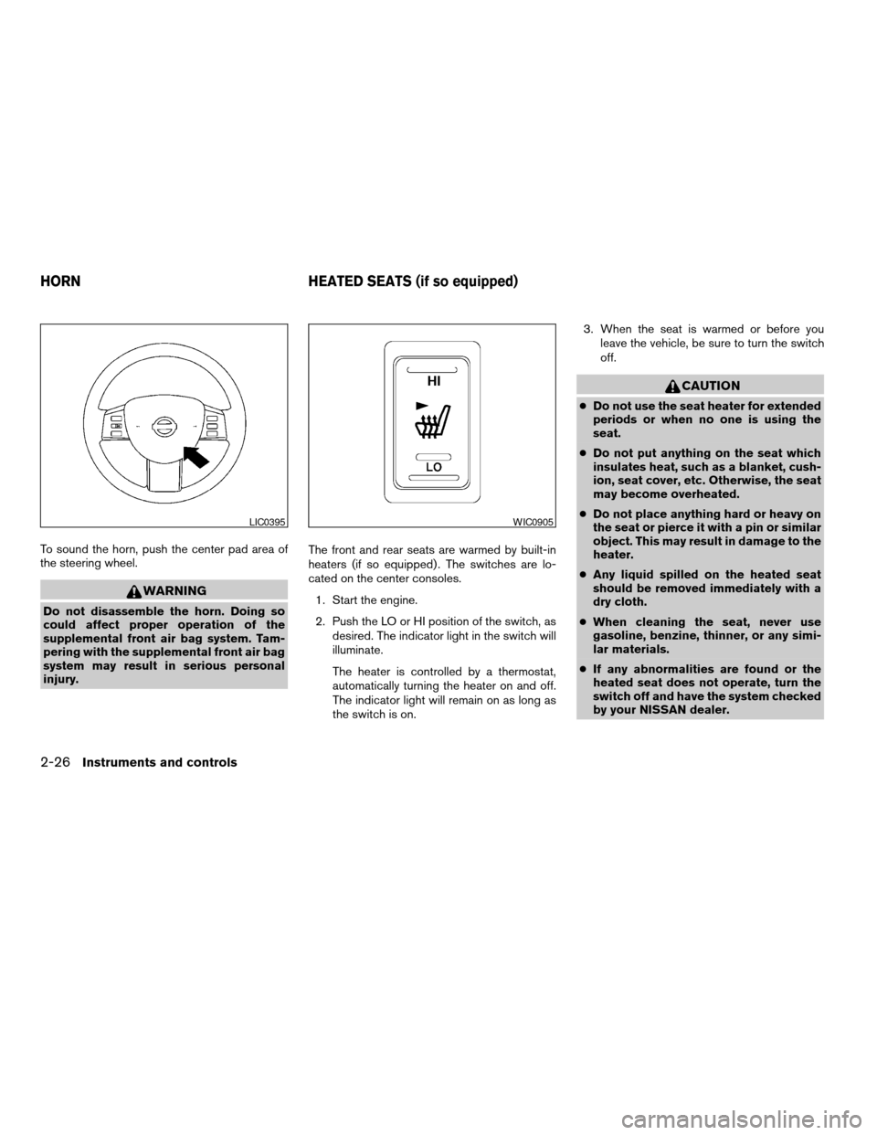
To sound the horn, push the center pad area of
the steering wheel.
WARNING
Do not disassemble the horn. Doing so
could affect proper operation of the
supplemental front air bag system. Tam-
pering with the supplemental front air bag
system may result in serious personal
injury.The front and rear seats are warmed by built-in
heaters (if so equipped) . The switches are lo-
cated on the center consoles.
1. Start the engine.
2. Push the LO or HI position of the switch, as
desired. The indicator light in the switch will
illuminate.
The heater is controlled by a thermostat,
automatically turning the heater on and off.
The indicator light will remain on as long as
the switch is on.3. When the seat is warmed or before you
leave the vehicle, be sure to turn the switch
off.
CAUTION
cDo not use the seat heater for extended
periods or when no one is using the
seat.
cDo not put anything on the seat which
insulates heat, such as a blanket, cush-
ion, seat cover, etc. Otherwise, the seat
may become overheated.
cDo not place anything hard or heavy on
the seat or pierce it with a pin or similar
object. This may result in damage to the
heater.
cAny liquid spilled on the heated seat
should be removed immediately with a
dry cloth.
cWhen cleaning the seat, never use
gasoline, benzine, thinner, or any simi-
lar materials.
cIf any abnormalities are found or the
heated seat does not operate, turn the
switch off and have the system checked
by your NISSAN dealer.
LIC0395WIC0905
HORN HEATED SEATS (if so equipped)
2-26Instruments and controls
ZREVIEW COPYÐ2006 Maxima(max)
Owners ManualÐUSA_English(nna)
06/22/05Ðtbrooks
X
Page 125 of 312
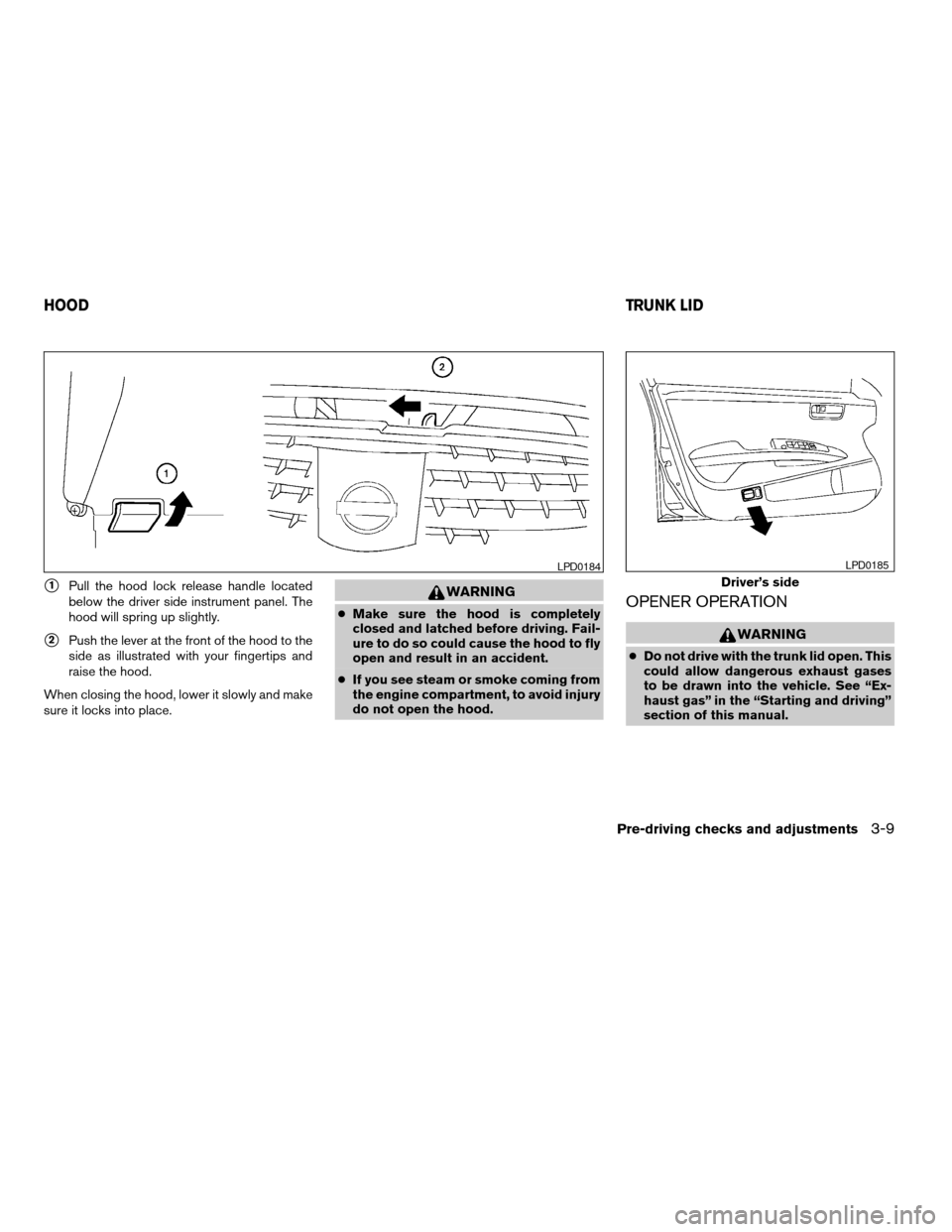
s1Pull the hood lock release handle located
below the driver side instrument panel. The
hood will spring up slightly.
s2Push the lever at the front of the hood to the
side as illustrated with your fingertips and
raise the hood.
When closing the hood, lower it slowly and make
sure it locks into place.
WARNING
cMake sure the hood is completely
closed and latched before driving. Fail-
ure to do so could cause the hood to fly
open and result in an accident.
cIf you see steam or smoke coming from
the engine compartment, to avoid injury
do not open the hood.OPENER OPERATION
WARNING
cDo not drive with the trunk lid open. This
could allow dangerous exhaust gases
to be drawn into the vehicle. See “Ex-
haust gas” in the “Starting and driving”
section of this manual.
LPD0184
Driver’s side
LPD0185
HOODTRUNK LID
Pre-driving checks and adjustments3-9
ZREVIEW COPYÐ2006 Maxima(max)
Owners ManualÐUSA_English(nna)
06/22/05Ðtbrooks
X
Page 128 of 312
FUEL FILLER CAP
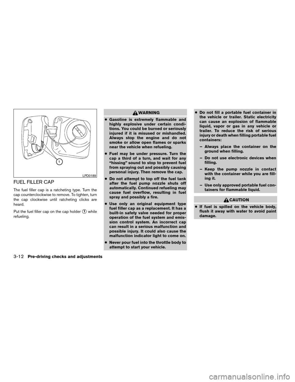
The fuel filler cap is a ratcheting type. Turn the
cap counterclockwise to remove. To tighten, turn
the cap clockwise until ratcheting clicks are
heard.
Put the fuel filler cap on the cap holder
s1while
refueling.
WARNING
cGasoline is extremely flammable and
highly explosive under certain condi-
tions. You could be burned or seriously
injured if it is misused or mishandled.
Always stop the engine and do not
smoke or allow open flames or sparks
near the vehicle when refueling.
cFuel may be under pressure. Turn the
cap a third of a turn, and wait for any
“hissing” sound to stop to prevent fuel
from spraying out and possibly causing
personal injury. Then remove the cap.
cDo not attempt to top off the fuel tank
after the fuel pump nozzle shuts off
automatically. Continued refueling may
cause fuel overflow, resulting in fuel
spray and possibly a fire.
cUse only an original equipment type
fuel filler cap as a replacement. It has a
built-in safety valve needed for proper
operation of the fuel system and emis-
sion control system. An incorrect cap
can result in a serious malfunction and
possible injury. It could also cause the
malfunction indicator light to come on.
cNever pour fuel into the throttle body to
attempt to start your vehicle.cDo not fill a portable fuel container in
the vehicle or trailer. Static electricity
can cause an explosion of flammable
liquid, vapor or gas in any vehicle or
trailer. To reduce the risk of serious
injury or death when filling portable fuel
containers:
– Always place the container on the
ground when filling.
– Do not use electronic devices when
filling.
– Keep the pump nozzle in contact
with the container while you are fill-
ing it.
– Use only approved portable fuel con-
tainers for flammable liquid.
CAUTION
cIf fuel is spilled on the vehicle body,
flush it away with water to avoid paint
damage.
LPD0189
3-12Pre-driving checks and adjustments
ZREVIEW COPYÐ2006 Maxima(max)
Owners ManualÐUSA_English(nna)
06/22/05Ðtbrooks
X
Page 136 of 312

3. Adjust the driver’s seat, steering column and
outside mirrors to the desired positions by
manually operating each adjusting switch.
For additional information, see “Seats” in the
“Safety—Seats, seat belts and supplemen-
tal restraint system” section and “Tilting tele-
scopic steering column” and “Outside mir-
rors” earlier in this section.
During this step, do not turn the ignition to
any positions other than ON.
4. Push the SET switch and, within 5 seconds,
push the memory switch (1 or 2) fully for at
least 1 second.
The indicator light for the pushed memory
switch will come on and stay on for approxi-
mately 5 seconds after pushing the switch.
After the indicator light goes off, the se-
lected positions are stored in the selected
memory (1 or 2) .
If memory is stored in the same memory switch,
the previous memory will be deleted.
Linking a keyfob to a stored memory
position
Each keyfob can be linked to a stored memory
position (memory switch 1 or 2) with the follow-
ing procedure.1.
Follow the steps for storing a memory position.
2. While the indicator light for the memory
switch being set is illuminated for 5 sec-
onds, press the
button on the keyfob.
The indicator light will blink. After the indica-
tor light goes off, the keyfob is linked to that
memory setting.
With the key removed from the ignition switch,
press the
button on the keyfob. The driv-
er’s seat and outside mirrors will move to the
memorized position.
NOTE:
If a new memory position is saved to the
memory switch, the keyfob automatically
re-links.
Procedure for storing the outside
mirror positions for best visibility when
backing up
An outside mirror position for backing up can be
stored for each memory switch (1 and 2) .
1. Set the parking brake.
2.
Turn the ignition ON. (Do not start the engine.)
3. Push the memory switch 1 or 2 fully for at
least 1 second to operate the automatic
drive positioner.4. Turn the outside mirror control switch to L
(left) .
5. Depress the brake pedal.
6. Move the automatic transmission shift lever
to R (Reverse) .
7. Adjust the mirror to the desired viewing po-
sition for backing up by operating the out-
side mirror control switch.
8. Push the SET switch and, within 5 seconds,
push the memory switch 1 or 2 selected in
step 3 fully for at least 1 second.
cThe indicator light for the pushed memory
switch will come on and stay on for approxi-
mately 5 seconds after pushing the switch.
After the indicator light goes off, the se-
lected mirror position is stored in the se-
lected memory (1 or 2) .
9. Turn the outside mirror control switch to R
(right) . Repeat the above procedure to ad-
just the right mirror position and store in the
selected memory.
cWhen the driver’s seat, accelerator and
brake pedals, and outside mirrors are not in
the memorized position, the outside mirror
will move with the initial tilt-down angle.
3-20Pre-driving checks and adjustments
ZREVIEW COPYÐ2006 Maxima(max)
Owners ManualÐUSA_English(nna)
06/22/05Ðtbrooks
X
Page 192 of 312
cMake sure the area around the vehicle is
clear.
cCheck fluid levels such as engine oil, cool-
ant, brake and clutch fluid, and window
washer fluid as frequently as possible, or at
least whenever you refuel.
cCheck that all windows and lights are clean.
cVisually inspect tires for their appearance
and condition. Also check tires for proper
inflation.
cLock all doors.
cPosition seat and adjust head restraints.
cAdjust inside and outside mirrors.
cFasten seat belts and ask all passengers to
do likewise.
cCheck the operation of warning lights when
the key is turned to the ON (3) position. See
“Warning/indicator lights and audible re-
minders” in the “Instruments and controls”
section of this manual.1. Apply the parking brake.
2.Automatic transmission:
Move the shift selector lever to P (Park) or N
(Neutral) . P (Park) is recommended.
The shift selector lever cannot be
moved out of P (Park) and into any of
the other gear positions if the ignition
key is turned to the OFF position or if
the key is removed from the ignition
switch.
The starter is designed not to operate if
the shift selector lever is in any of the
driving positions.
Manual transmission:
Move the shift lever to N (Neutral) . Depress
the clutch pedal to the floor while cranking
the engine.
The starter is designed not to operate
unless the clutch pedal is fully de-
pressed.
3. Crank the enginewith your foot off the
accelerator pedalby turning the ignition
key to START. Release the key when the
engine starts. If the engine starts, but fails to
run, repeat the above procedure.cIf the engine is very hard to start in ex-
tremely cold weather or when restarting,
depress the accelerator pedal a little (ap-
proximately 1/3 to the floor) and hold it
and then crank the engine. Release the
key and the accelerator pedal when the
engine starts.
cIf the engine is very hard to start because
it is flooded, depress the accelerator
pedal all the way to the floor and hold it.
Crank the engine for 5-6 seconds. After
cranking the engine, release the accel-
erator pedal. Crank the enginewith your
foot off the accelerator pedalby turn-
ing the ignition key to START. Release the
key when the engine starts. If the engine
starts, but fails to run, repeat the above
procedure.
CAUTION
Do not operate the starter for more than
15 seconds at a time. If the engine does
not start, turn the key off and wait 10
seconds before cranking again, otherwise
the starter could be damaged.
BEFORE STARTING THE ENGINE STARTING THE ENGINE
5-6Starting and driving
ZREVIEW COPYÐ2006 Maxima(max)
Owners ManualÐUSA_English(nna)
06/22/05Ðtbrooks
X
Page 196 of 312
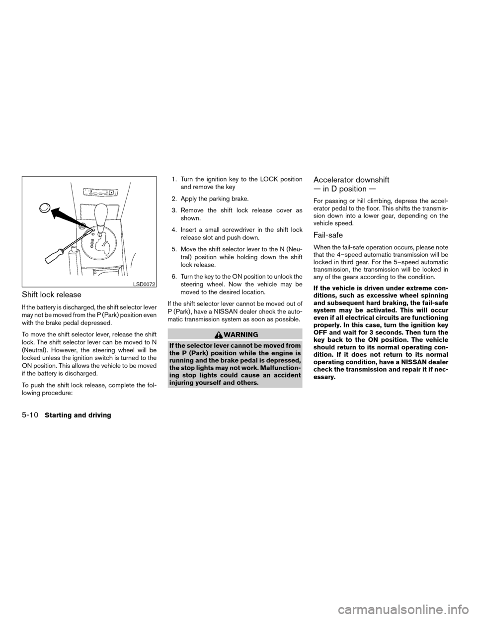
Shift lock release
If the battery is discharged, the shift selector lever
may not be moved from the P (Park) position even
with the brake pedal depressed.
To move the shift selector lever, release the shift
lock. The shift selector lever can be moved to N
(Neutral) . However, the steering wheel will be
locked unless the ignition switch is turned to the
ON position. This allows the vehicle to be moved
if the battery is discharged.
To push the shift lock release, complete the fol-
lowing procedure:1. Turn the ignition key to the LOCK position
and remove the key
2. Apply the parking brake.
3. Remove the shift lock release cover as
shown.
4. Insert a small screwdriver in the shift lock
release slot and push down.
5. Move the shift selector lever to the N (Neu-
tral) position while holding down the shift
lock release.
6. Turn the key to the ON position to unlock the
steering wheel. Now the vehicle may be
moved to the desired location.
If the shift selector lever cannot be moved out of
P (Park) , have a NISSAN dealer check the auto-
matic transmission system as soon as possible.
WARNING
If the selector lever cannot be moved from
the P (Park) position while the engine is
running and the brake pedal is depressed,
the stop lights may not work. Malfunction-
ing stop lights could cause an accident
injuring yourself and others.
Accelerator downshift
— in D position —
For passing or hill climbing, depress the accel-
erator pedal to the floor. This shifts the transmis-
sion down into a lower gear, depending on the
vehicle speed.
Fail-safe
When the fail-safe operation occurs, please note
that the 4–speed automatic transmission will be
locked in third gear. For the 5–speed automatic
transmission, the transmission will be locked in
any of the gears according to the condition.
If the vehicle is driven under extreme con-
ditions, such as excessive wheel spinning
and subsequent hard braking, the fail-safe
system may be activated. This will occur
even if all electrical circuits are functioning
properly. In this case, turn the ignition key
OFF and wait for 3 seconds. Then turn the
key back to the ON position. The vehicle
should return to its normal operating con-
dition. If it does not return to its normal
operating condition, have a NISSAN dealer
check the transmission and repair it if nec-
essary.
LSD0072
5-10Starting and driving
ZREVIEW COPYÐ2006 Maxima(max)
Owners ManualÐUSA_English(nna)
06/22/05Ðtbrooks
X
Page 207 of 312
cIf brake related parts such as brake
pads, rotors and calipers are not stan-
dard equipment or are extremely dete-
riorated, the vehicle dynamic control
system may not operate properly and
the vehicle dynamic control off indica-
tor light may come on.
cDo not modify the vehicle’s suspension.
If suspension parts such as shock ab-
sorbers, struts, springs, stabilizer bars
and bushings are not NISSAN approved
for your vehicle or are extremely dete-
riorated the vehicle dynamic control
system may not operate properly. This
could adversely affect vehicle handling
performance, and the VDC OFF indica-
tor light may come on.
cWhen driving on extremely inclined sur-
faces such as higher banked corners,
the vehicle dynamic control system may
not operate properly and the VDC OFF
indicator light may come on. Do not
drive on these types of roads.
cWhen driving on an unstable surface
such as a turntable, ferry, elevator or
ramp, the vehicle dynamic control off
indicator light may illuminate. This is
not a malfunction. Restart the engine
after driving onto a stable surfacecIf wheels or tires other than the recom-
mended ones are used, the vehicle dy-
namic control system may not operate
properly and the vehicle dynamic con-
trol off indicator light may come on.
cThe vehicle dynamic control system is
not a substitute for winter tires or tire
chains on a snow covered road.FREEING A FROZEN DOOR LOCK
To prevent a door lock from freezing, apply de-
icer through the key hole. If the lock becomes
frozen, heat the key before inserting it into the key
hole or use the remote keyless entry keyfob (if so
equipped) .
ANTI-FREEZE
In the winter when it is anticipated that the tem-
perature will drop below 32°F (0°C) , check the
anti-freeze to assure proper winter protection.
For details, see ‘‘Engine cooling system’’ in the
‘‘Maintenance and do-it-yourself’’ section of this
manual.
BATTERY
If the battery is not fully charged during extremely
cold weather conditions, the battery fluid may
freeze and damage the battery. To maintain maxi-
mum efficiency, the battery should be checked
regularly. For details, see ‘‘Battery’’ in the ‘‘Main-
tenance and do-it-yourself’’ section of this
manual.
COLD WEATHER DRIVING
Starting and driving5-21
ZREVIEW COPYÐ2006 Maxima(max)
Owners ManualÐUSA_English(nna)
06/22/05Ðtbrooks
X
Page 208 of 312
DRAINING OF COOLANT WATER
If the vehicle is to be left outside without anti-
freeze, drain the cooling system, including the
engine block. Refill before operating the vehicle.
For details, see ‘‘Changing engine coolant’’ in the
‘‘Maintenance and do-it-yourself’’ section of this
manual.
TIRE EQUIPMENT
1. SUMMER tires have a tread designed to
provide superior performance on dry pave-
ment. However, the performance of these
tires will be substantially reduced in snowy
and icy conditions. If you operate your ve-
hicle on snowy or icy roads, NISSAN recom-
mends the use of MUD & SNOW or ALL
SEASON TIRES on all four wheels. Please
consult a NISSAN dealer for the tire type,
size, speed rating and availability informa-
tion.
2. For additional traction on icy roads, studded
tires may be used. However, some U.S.
states and Canadian provinces prohibit their
use. Check local, state and provincial laws
before installing studded tires.
Skid and traction capabilities of studded
snow tires on wet or dry surfaces may be
poorer than that of non-studded snow tires.3. Tire chains may be used.
CAUTION
Tire chains/cables cannot be installed on
P245/45R18 size tires. Installation of the
tire chains/cables on P245/45R18 size
tires will cause damage to the vehicle. If
you plan to use tire chains/cables, you
should install P225/55R17 size tires on
your vehicle.
Use of tire chains may be prohibited accord-
ing to location. Check the local laws before
installing tire chains. When installing tire
chains, make sure they are the proper size
for the tires on your vehicle and are installed
according to the chain manufacturer’s sug-
gestions.Use only SAE Class “S”
chains.Class “S” chains are used on ve-
hicles with restricted tire to vehicle clear-
ance. Vehicles that can use Class “S” chains
are designed to meet the minimum clear-
ances between the tire and the closest ve-
hicle suspension or body component re-
quired to accommodate the use of a winter
traction device (tire chains or cables) . The
minimum clearances are determined using
the factory equipped tire size. Other types
may damage your vehicle. Use chain ten-
sioners when recommended by the tire
chain manufacturer to ensure a tight fit.Loose end links of the tire chain must be
secured or removed to prevent the possibil-
ity of whipping action damage to the fenders
or underbody. If possible, avoid fully loading
your vehicle when using tire chains. In addi-
tion, drive at a reduced speed. Otherwise,
your vehicle may be damaged and/or vehicle
handling and performance may be adversely
affected.
Never install tire chains on spare tires. Do
not use tire chains on dry roads.
SPECIAL WINTER EQUIPMENT
It is recommended that the following items be
carried in the vehicle during winter:
cA scraper and stiff-bristled brush to remove
ice and snow from the windows and wiper
blades.
cA sturdy, flat board to be placed under the
jack to give it firm support.
cA shovel to dig the vehicle out of snowdrifts.
cExtra window washer fluid to refill the reser-
voir tank.
5-22Starting and driving
ZREVIEW COPYÐ2006 Maxima(max)
Owners ManualÐUSA_English(nna)
06/22/05Ðtbrooks
X
Page 219 of 312
If your vehicle is overheating (indicated by an
extremely high temperature gauge reading) , or if
you feel a lack of engine power, detect abnormal
noise, etc. take the following steps.
WARNING
cDo not continue to drive if your vehicle
overheats. Doing so could cause engine
damage or a vehicle fire.
cTo avoid the danger of being scalded,
never remove the radiator cap while the
engine is still hot. When the radiator
cap is removed, pressurized hot water
will spurt out, possibly causing serious
injury.
cDo not open the hood if steam is com-
ing out.
1. Move the vehicle safely off the road, apply
the parking brake and move the shift lever to
N (Neutral) (manual transmission) or to P
(Park) (automatic transmission) .
Do not stop the engine.
2. Turn off the air conditioner (if so equipped) .
Open all the windows, move the heater or air
conditioner temperature control to maximum
hot and fan control to high speed.3. Get out of the vehicle. Look and listen for
steam or coolant escaping from the radiator
before opening the hood. (If steam or cool-
ant is escaping, turn off the engine.) Do not
open the hood further until no steam or
coolant can be seen.
4. Open the engine hood.
WARNING
If steam or water is coming from the en-
gine, stand clear to prevent getting
burned.
5. Visually check drive belts for damage or
looseness. Also check if the cooling fan is
running. The radiator hoses and radiator
should not leak water. If coolant is leaking,
the water pump belt is missing or loose, or
the cooling fan does not run, stop the en-
gine.
WARNING
Be careful not to allow your hands, hair,
jewelry or clothing to come into contact
with, or get caught in, engine belts or the
engine cooling fan. The engine cooling
fan can start at any time when the coolant
temperature is high.6. After the engine cools down, check the cool-
ant level in the engine coolant reservoir tank
with the engine running. Add coolant to the
engine coolant reservoir tank if necessary.
Have your vehicle repaired at a NISSAN
dealer.
IF YOUR VEHICLE OVERHEATS
In case of emergency6-9
ZREVIEW COPYÐ2006 Maxima(max)
Owners ManualÐUSA_English(nna)
06/22/05Ðtbrooks
X
Page 231 of 312

8 Maintenance and do-it-yourself
Maintenance requirements..........................8-2
General maintenance..............................8-2
Explanation of general maintenance items.........8-2
Maintenance precautions...........................8-5
Engine compartment check locations................8-6
Engine cooling system.............................8-7
Checking engine coolant level...................8-7
Changing engine coolant........................8-8
Engine oil.........................................8-8
Checking engine oil level........................8-8
Changing engine oil............................8-9
Changing engine oil filter.......................8-10
5-speed automatic transmission fluid...............8-11
Power steering fluid...............................8-11
Brake and clutch fluid.............................8-12
Brake fluid....................................8-12
Clutch fluid...................................8-12
Window washer fluid.............................8-13
Window washer fluid reservoir..................8-13
Battery..........................................8-13
Jump starting.................................8-15
Drive belts.......................................8-15
Spark plugs......................................8-16Replacing spark plugs.........................8-16
Air cleaner.......................................8-16
In-cabin microfilter.............................8-17
Windshield wiper blades..........................8-20
Cleaning.....................................8-20
Replacing....................................8-20
Parking brake and brake pedal.....................8-21
Checking parking brake........................8-21
Checking brake pedal..........................8-21
Brake booster.................................8-22
Fuses...........................................8-22
Engine compartment...........................8-23
Passenger compartment.......................8-24
Keyfob battery replacement........................8-26
Lights...........................................8-27
Headlights....................................8-27
Exterior and interior lights.......................8-28
Wheels and tires.................................8-33
Tire pressure..................................8-33
Tire labeling...................................8-37
Types of tires..................................8-40
Tire chains....................................8-41
Changing wheels and tires.....................8-41
ZREVIEW COPYÐ2006 Maxima(max)
Owners ManualÐUSA_English(nna)
06/23/05Ðtbrooks
X