sensor NISSAN MAXIMA 2021 Owner´s Manual
[x] Cancel search | Manufacturer: NISSAN, Model Year: 2021, Model line: MAXIMA, Model: NISSAN MAXIMA 2021Pages: 476, PDF Size: 3.32 MB
Page 191 of 476

VANITY MIRRORS
To access the vanity mirror, pull the sun
visor down and flip open the mirror cover.
The vanity mirror will illuminate when the
mirror cover is open.
AUTOMATIC ANTI-GLARE
REARVIEW MIRROR
The inside mirror is designed so that it au-
tomatically dims during night time condi-
tions and according to the intensity of the
headlights of the vehicle following you. The
automatic anti-glare feature is activated
when the ignition switch is in the ON
position.
NOTE:
Do not hang any objects over the sen-
sors
O1or apply glass cleaner to the sen-
sors. Doing so will reduce the sensitivity
of the sensors, resulting in improper
operation.
Type A (if so equipped)
The inside mirror is designed so that it au-
tomatically dims during night time condi-
tions and according to the intensity of the
headlights of the vehicle following you. The
automatic anti-glare feature is activated
when the ignition switch is in the ON
position.
LPD2312LPD2418
MIRRORS
Pre-driving checks and adjustments3-27
Page 192 of 476

Type B (if so equipped)
The indicator lightO2will illuminate when
the automatic anti-glare feature is
operating.
NOTE:
Do not hang any objects over the sen-
sors
O1or apply glass cleaner to the sen-
sors. Doing so will reduce the sensitivity
of the sensors, resulting in improper
operation.
To turn off the automatic anti-glare feature,
press the O button. The indicator light will
turn off. To turn on the automatic anti-glare feature
again, press the I button. The indicator light
will turn on.
For additional information, see “HomeLink®
Universal Transceiver” (P. 2-73).
OUTSIDE MIRRORS
The outside mirror remote control will op-
erate only when the ignition switch is in the
ACC or ON position.
Move the small switch
O1to select the right
or lef t mirror. Adjust each mirror to the de-
sired position using the large switch
O2.
Move the small switch
O1to the center
(neutral) position to prevent accidentally
moving the mirror.
LPD0469LPD2352
3-28Pre-driving checks and adjustments
Page 227 of 476

OPERATING TIPS
The sunload sensor, located on the top
center of the instrument panel, helps the
system maintain a constant temperature.
Do not put anything on or around this
sensor.• When the climate system is in automatic
operation and the engine coolant tem-
perature and outside air temperature are
low, the air flow outlet may default to de-
froster mode for a maximum of 2 min-
utes 30 seconds. This is not a malfunc-
tion. Af ter the engine coolant
temperature warms up, the air flow outlet
will return to foot mode and operation will
continue normally.
• When the outside and interior cabin tem- peratures are moderate to high, the in-
take setting may default to turn off air
recirculation to allow fresh air into the
passenger compartment. You may no-
tice air flow from the foot mode, bi-level
mode or side demist vent outlets for a
maximum of 15 seconds. This may occur
when the previous climate setting was
turned off. This is not a malfunction. Af ter
the initial warm air is expelled, the intake
will return to automatic control, the air
flow outlet will return to previous settings,
and operation will continue normally. To
exit, press any climate control button. • Keep the moonroof (if so equipped)
closed while the air conditioner is in
operation.
• If you feel that the air flow mode you have selected and the outlets the air is coming
out do not match, select the
mode.
• When you change the air flow mode, you may feel air flow from the foot outlets for
just a moment. This is not a malfunction.
LHA5021
Monitor, climate, audio, phone and voice recognition systems4-31
Page 237 of 476

•When replacing a wheel without the
TPMS such as the spare tire, when a
spare tire is mounted or a wheel is
replaced, tire pressure will not be in-
dicated, the TPMS will not function
and the low tire pressure warning
light will flash for approximately 1
minute. The light will remain on af ter
1 minute. Have your tires replaced
and/or TPMS system reset as soon as
possible. It is recommended that you
visit a NISSAN dealer for this service.
• Replacing tires with those not origi-
nally specified by NISSAN could af-
fect the proper operation of the
TPMS.
• Do not inject any tire liquid or aerosol
tire sealant into the tires, as this may
cause a malfunction of the tire pres-
sure sensors.
CAUTION
Do not place metalized film or any
metal parts (antenna, etc.) on the win-
dows. This may cause poor reception of
the signals from the tire pressure sen-
sors, and the TPMS will not function
properly. Some devices and transmitters may tem-
porarily interfere with the operation of the
TPMS and cause the low tire pressure
warning light to illuminate.
Some examples are:
• Facilities or electric devices using similar
radio frequencies are near the vehicle.
• If a transmitter set to similar frequencies is being used in or near the vehicle.
• If a computer (or similar equipment) or a DC/AC converter is being used in or near
the vehicle.
The low tire pressure warning light may
illuminate in the following cases:
• If the vehicle is equipped with a wheel and tire without TPMS
• If the TPMS has been replaced and the ID has not been registered
• If the wheel is not originally specified by NISSAN
FCC Notice:
For USA:
This device complies with Part 15 of the
FCC Rules. Operation is subject to the fol-
lowing two conditions: (1) This device
may not cause harmful interference, and
(2) this device must accept any interfer- ence received, including interference
that may cause undesired operation.
NOTE:
Changes or modifications not ex-
pressly approved by the party re-
sponsible for compliance could void
the user's authority to operate the
equipment.
For Canada:
This device complies with Industry
Canada licence-exempt RSS standard(s).
Operation is subject to the following two
conditions: (1) this device may not cause
harmful interference, and (2) this device
must accept any interference received,
including interference that may cause
undesired operation of the device.
TPMS with Easy-Fill Tire Alert
When adding air to an under-inflated tire,
the TPMS with Easy-Fill Tire Alert provides
visual and audible signals outside the ve-
hicle to help you inflate the tires to the rec-
ommended COLD tire pressure.
Starting and driving5-7
Page 238 of 476

Vehicle set-up
1. Park the vehicle in a safe and level place.
2. Apply the parking brake and place theshif t lever in the P (Park) position.
3. Place the ignition switch in the ON posi- tion. Do not start the engine.
Operation
1. Add air to the tire.
2. Af ter a few seconds, the hazard indica- tors will start flashing.
3. When the designated pressure is reached, the horn beeps once and the
hazard indicators stop flashing.
4. Perform the above steps for each tire. • If the tire is over-inflated more thanapproximately 4 psi (30 kPa), the horn
beeps and the hazard indicators flash
three times. To correct the pressure,
push the core of the valve stem on the
tire briefly to release pressure. When
the pressure reaches the designated
pressure, the horn beeps once.
• If the hazard indicator does not flash within approximately 15 seconds af ter
starting to inflate the tire, it indicates
that the Easy-Fill Tire Alert is not
operating. • The TPMS will not activate the Easy-Fill
Tire Alert under the following
conditions:– If there is interference from an exter- nal device or transmitter.
– The air pressure from the inflation device is not sufficient to inflate the
tire.
– There is a malfunction in the TPMS.
– There is a malfunction in the horn or hazard indicators.
– The identification code of the tire pressure sensor is not registered to
the system.
– The battery of the tire pressure sen- sor is low.
• If the Easy-Fill Tire Alert does not oper- ate due to TPMS interference, move
the vehicle about 3 f t (1 m) backward
or forward and try again.
If the Easy-Fill Tire Alert is not working, use a
tire pressure gauge.
AVOIDING COLLISION AND
ROLLOVER
WARNING
Failure to operate this vehicle in a safe
and prudent manner may result in loss
of control or an accident. Be alert and drive defensively at all times.
Obey all traffic regulations. Avoid excessive
speed, high speed cornering, or sudden
steering maneuvers, because these driving
practices could cause you to lose control of
your vehicle.
As with any vehicle, loss of control could
result in a collision with other vehicles or
objects or cause the vehicle to roll over,
particularly if the loss of control causes
the vehicle to slide sideways.
Be attentive at all times, and avoid driving
when tired. Never drive when under the in-
fluence of alcohol or drugs (including pre-
scription or over-the-counter drugs which
may cause drowsiness). Always wear your
seat belt as outlined in the “Safety – Seats,
seat belts and supplemental restraint sys-
tem” section of this manual, and also in-
struct your passengers to do so.
Seat belts help reduce the risk of injury in
collisions and rollovers.
In a rollover crash,
an unbelted person is significantly more
likely to die than a person wearing a seat
belt.
5-8Starting and driving
Page 266 of 476
WARNING
Failure to follow the warnings and in-
structions for proper use of the BSW
system could result in serious injury or
death.
• The BSW system is not a replacement
for proper driving procedures and is
not designed to prevent contact with
vehicles or objects. When changing
lanes, always use the side and rear
mirrors and turn and look in the di-
rection your vehicle will move to en-
sure it is safe to change lanes. Never
rely solely on the BSW system.
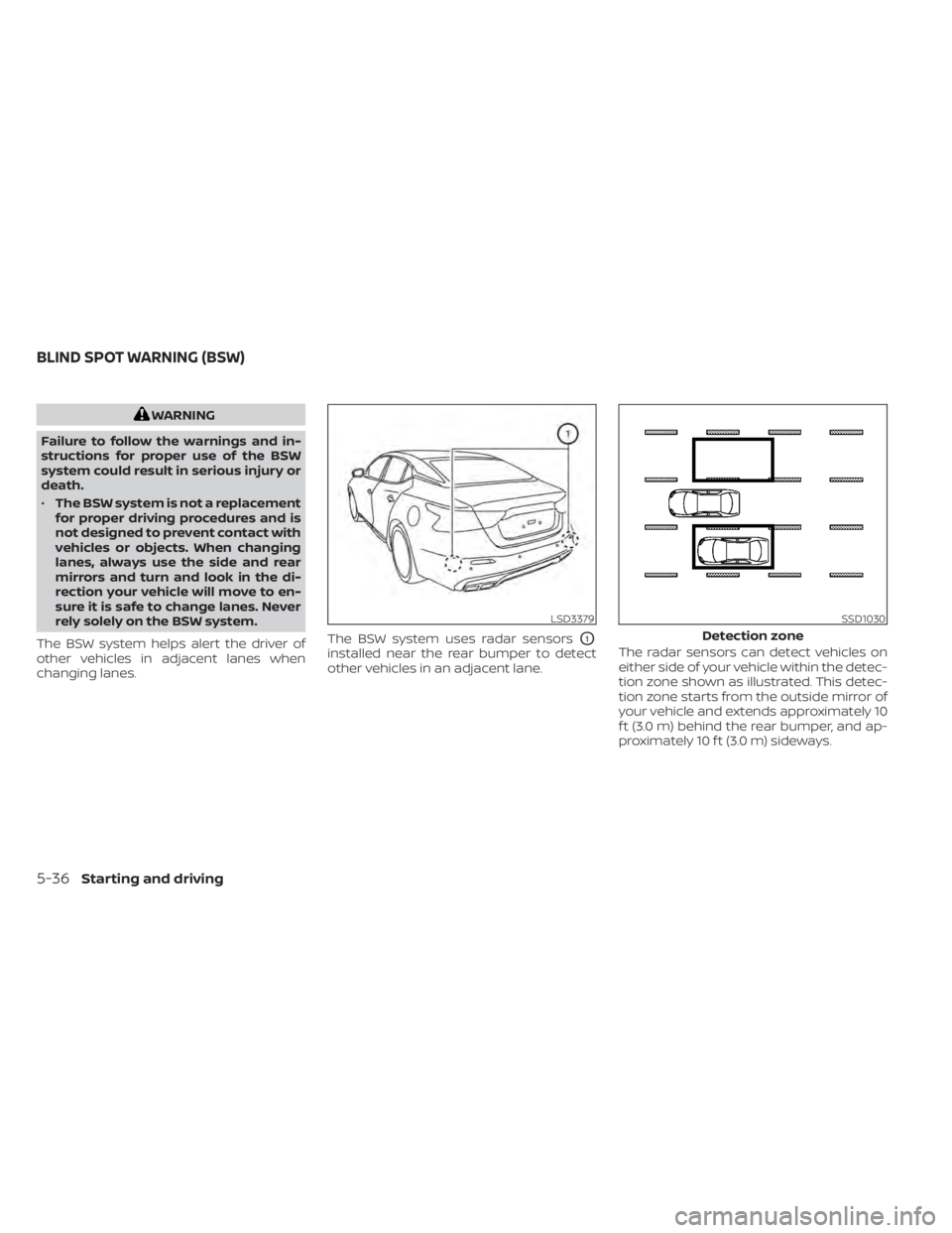
The BSW system helps alert the driver of
other vehicles in adjacent lanes when
changing lanes. The BSW system uses radar sensors
O1
installed near the rear bumper to detect
other vehicles in an adjacent lane.
The radar sensors can detect vehicles on
either side of your vehicle within the detec-
tion zone shown as illustrated. This detec-
tion zone starts from the outside mirror of
your vehicle and extends approximately 10
f t (3.0 m) behind the rear bumper, and ap-
proximately 10 f t (3.0 m) sideways.
LSD3379SSD1030
Detection zone
BLIND SPOT WARNING (BSW)
5-36Starting and driving
Page 267 of 476
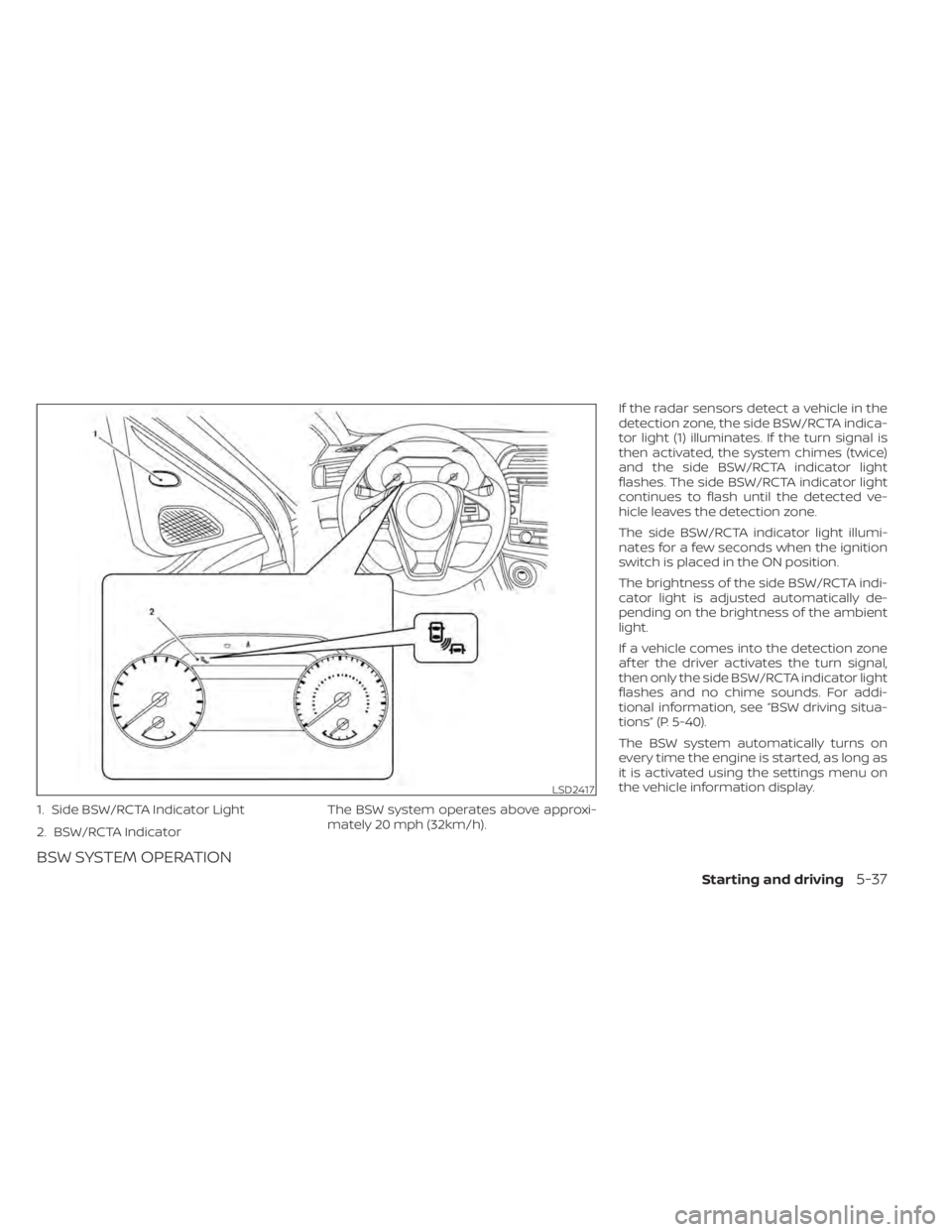
1. Side BSW/RCTA Indicator Light
2. BSW/RCTA Indicator
BSW SYSTEM OPERATION
The BSW system operates above approxi-
mately 20 mph (32km/h).If the radar sensors detect a vehicle in the
detection zone, the side BSW/RCTA indica-
tor light (1) illuminates. If the turn signal is
then activated, the system chimes (twice)
and the side BSW/RCTA indicator light
flashes. The side BSW/RCTA indicator light
continues to flash until the detected ve-
hicle leaves the detection zone.
The side BSW/RCTA indicator light illumi-
nates for a few seconds when the ignition
switch is placed in the ON position.
The brightness of the side BSW/RCTA indi-
cator light is adjusted automatically de-
pending on the brightness of the ambient
light.
If a vehicle comes into the detection zone
af ter the driver activates the turn signal,
then only the side BSW/RCTA indicator light
flashes and no chime sounds. For addi-
tional information, see “BSW driving situa-
tions” (P. 5-40).
The BSW system automatically turns on
every time the engine is started, as long as
it is activated using the settings menu on
the vehicle information display.
LSD2417
Starting and driving5-37
Page 269 of 476
• When the BSW system is turned on, theBSW/RCTA indicator (white) in the ve-
hicle information display illuminates.
BSW SYSTEM LIMITATIONS
WARNING
Listed below are the system limitations
for the BSW system. Failure to operate
the vehicle in accordance with these
system limitations could result in seri-
ous injury or death.
• The BSW system cannot detect all ve-
hicles under all conditions.
• The radar sensors may not be able to
detect and activate BSW when cer-
tain objects are present such as:
– Pedestrian, bicycles, animals.
– Vehicles such as motorcycles, low
height vehicles, or high ground
clearance vehicles.
– Oncoming vehicles.
– Vehicles remaining in the detec-
tion zone when you accelerate
from a stop.
– A vehicle merging into an adjacent
lane at a speed approximately the
same as your vehicle. –
A vehicle approaching rapidly
from behind.
– A vehicle which your vehicle over-
takes rapidly.
– A vehicle that passes through the
detection zone quickly.
– When overtaking several vehicles
in a row, the vehicles af ter the first
vehicle may not be detected if
they are traveling close together.
• The radar sensors’ detection zone is
designed based on a standard lane
width. When driving in a wider lane,
the radar sensors may not detect ve-
hicles in an adjacent lane. When driv-
ing in a narrow lane, the radar sen-
sors may detect vehicles driving two
lanes away.
• The radar sensors are designed to ig-
nore most stationary objects; how-
ever, objects such as guardrails,
walls, foliage and parked vehicles
may occasionally be detected. This is
a normal operation condition.
• The following conditions may reduce
the ability of the radar to detect other
vehicles:
– Severe weather
– Road spray –
Ice/frost/snow/dirt build-up on
the vehicle
• Do not attach stickers (including
transparent material), install acces-
sories or apply additional paint near
the radar sensors. These conditions
may reduce the ability of the radar to
detect other vehicles.
• Excessive noise (for example, audio
system volume, open vehicle win-
dow) will interfere with the chime
sound, and it may not be heard.
Starting and driving5-39
Page 270 of 476
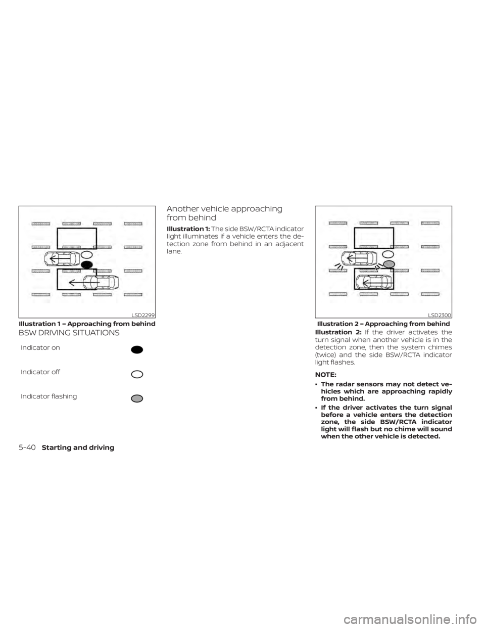
BSW DRIVING SITUATIONS
Indicator on
Indicator off
Indicator flashing
Another vehicle approaching
from behind
Illustration 1:The side BSW/RCTA indicator
light illuminates if a vehicle enters the de-
tection zone from behind in an adjacent
lane.
Illustration 2:If the driver activates the
turn signal when another vehicle is in the
detection zone, then the system chimes
(twice) and the side BSW/RCTA indicator
light flashes.
NOTE:
• The radar sensors may not detect ve- hicles which are approaching rapidly
from behind.
• If the driver activates the turn signal before a vehicle enters the detection
zone, the side BSW/RCTA indicator
light will flash but no chime will sound
when the other vehicle is detected.
LSD2299
Illustratio n 1 – Approaching from behind
LSD2300
Illustration2–Appro aching from behind
5-40Starting and driving
Page 271 of 476
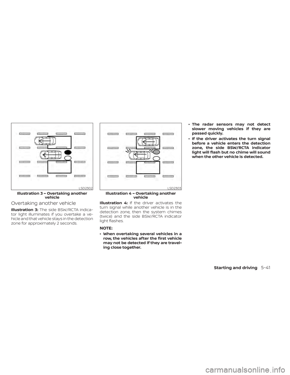
Overtaking another vehicle
Illustration 3:The side BSW/RCTA indica-
tor light illuminates if you overtake a ve-
hicle and that vehicle stays in the detection
zone for approximately 2 seconds. Illustration 4:
If the driver activates the
turn signal while another vehicle is in the
detection zone, then the system chimes
(twice) and the side BSW/RCTA indicator
light flashes.
NOTE:
• When overtaking several vehicles in a row, the vehicles af ter the first vehicle
may not be detected if they are travel-
ing close together. • The radar sensors may not detect
slower moving vehicles if they are
passed quickly.
• If the driver activates the turn signal before a vehicle enters the detection
zone, the side BSW/RCTA indicator
light will flash but no chime will sound
when the other vehicle is detected.
LSD2302
Illustratio n3–Over taking another
vehicle
LSD2303
Illustratio n4–Over taking another
vehicle
Starting and driving5-41