oil filter NISSAN MAXIMA 2021 Owner´s Manual
[x] Cancel search | Manufacturer: NISSAN, Model Year: 2021, Model line: MAXIMA, Model: NISSAN MAXIMA 2021Pages: 476, PDF Size: 3.32 MB
Page 109 of 476

Menu itemExplanation
OFF Doors will have to be manually unlocked.
Ignition OFF Doors will unlock when the ignition is turned off.
Shif t into Park Doors will unlock when the vehicle is shif ted into Park.
Wipers Displays the various wipers settings. For additional information, see “Wiper and washer switch” (P. 2-42).
Speed Dependent Allows user to turn the speed dependent feature on or off.
Rain Sensor Allows user to turn the rain sensor feature on or off.
Driving Position Displays the various driving position settings.
Exit Seat Slide Allows user to turn the exit seat slide on or off. For additional information, see “Memory seat” (P. 3-30).
Exit Steering Up Allows user to turn the exit steering up on or off. For additional information, see “Memory seat” (P. 3-30).
Remote Engine Start Allows user to turn the Remote Engine Start feature on or off. When turned on, the engine can be restarted
remotely. For additional information, see “Remote Engine Start” (P. 3-18).
Maintenance
The maintenance menu allows the user to set reminders for various vehicle maintenance items.
WARNING
The tire replacement indicator is not a substitute for regular tire checks, including tire pressure checks. For additional informa-
tion, see “Changing wheels and tires” (P. 8-34). Many factors including tire inflation, alignment, driving habits and road conditions
affect tire wear and when tires should be replaced. Setting the tire replacement indicator for a certain driving distance does not
mean your tires will last that long. Use the tire replacement indicator as a guide only and always perform regular tire checks.
Failure to perform regular tire checks, including tire pressure checks could result in tire failure. Serious vehicle damage could
occur and may lead to a collision, which could result in serious personal injury or death.
Menu item Explanation
Maintenance Displays various maintenance reminder options.
Oil and Filter Allows user to set a reminder at a specific interval or reset the current one.
Tire Allows user to set a reminder at a specific interval or reset the current one.
Other Allows user to set a reminder at a specific interval or reset the current one.
Instruments and controls2-23
Page 114 of 476
Oil and Filter
This indicator appears when the customer
set distance comes for changing the en-
gine oil and filter. You can set or reset the
distance for checking or replacing these
items. For scheduled maintenance items
and intervals, see “Maintenance and
schedules” (P. 9-2).
Other
This indicator appears when the customer
set distance is reached for checking or re-
placing maintenance items other than the
engine oil, oil filter and tires. Other mainte-
nance items can include such things as air
filter or tire rotation. The distance for
checking or replacing the items can be set
or reset.
Outside Temperature
Display
The outside temperature display appears
in the center region of the vehicle informa-
tion display.
Power turned off to save the battery
This message appears af ter the ignition
switch is automatically turned off. For addi-
tional information, see “Push-button igni-
tion switch positions” (P. 5-10).
Power will turn off to save the battery
This message appears in the vehicle infor-
mation display af ter a period of time if the
ignition switch is in the ACC or the ON po-
sition and if the vehicle is in P (Park). For
additional information, see “Push-button
ignition switch positions” (P. 5-10).
Push brake and start
switch to drive
This indicator appears when the shif t lever
is in the P (Park) position.
This indicator also appears when the ve-
hicle has been started using the Remote
Engine Start function.
This indicator means that the engine will
start by pushing the ignition switch with
the brake pedal depressed. You can start
the engine from any position of the ignition
switch.
Push ignition to OFF
Af ter the Push ignition to OFF warning ap-
pears, the warning will appear if the ignition
switch is placed in the ACC position when
the shif t lever is moved to the P (Park)
position.
To turn off the Push warning, place the ig-
nition switch in the ON position and then in
the LOCK position.
Release Parking Brake
This warning appears when the parking
brake is set and the vehicle is driven.
Reminder: Turn OFF
Headlights
This warning appears when the headlights
are lef t in the ON position when exiting the
vehicle. Place the headlight switch in the
OFF (if so equipped) or AUTO position. For
additional information, see “Headlight and
turn signal switch” (P. 2-45).
Rotate the steering and
push the start switch
This warning appears when the steering
lock cannot be unlocked or is malfunction-
ing. This warning may appear if the steer-
ing wheel is not aligned with the locking
2-28Instruments and controls
Page 377 of 476

8 Do-it-yourself
Maintenance precautions.......................8-2
Engine compartment check locations ...........8-3
Engine cooling system ..........................8-4
Checking engine coolant level ................8-5
Changing engine coolant ....................8-5
Engine oil .......................................8-6
Checking engine oil level .....................8-6
Changing engine oil and oil filter ..............8-6
Continuously Variable Transmission (CVT)
fluid ............................................ 8-10
Power Steering Fluid (PSF) .......................8-11
Brake fluid ....................................... 8-11
Windshield-washer fluid ........................8-12
Windshield-washer fluid reservoir ...........8-12
Battery......................................... 8-13
Jump starting ............................... 8-15
Drive belt ....................................... 8-15
Spark plugs .................................... 8-16
Replacing spark plugs .......................8-16
Air cleaner ..................................... 8-16
In-cabin microfilter .......................... 8-17Windshield wiper blades
........................8-17
Cleaning .................................... 8-17
Replacing ................................... 8-17
Brakes ......................................... 8-18
Fuses .......................................... 8-19
Engine compartment ....................... 8-19
Passenger compartment ...................8-20
Battery replacement ........................... 8-21
NISSAN Intelligent Key® ......................8-22
Lights .......................................... 8-23
Headlights .................................. 8-23
Front park/turn signal/side marker
light ......................................... 8-23
Fog lights (if so equipped) ...................8-23
Exterior and interior lights ...................8-24
Wheels and tires ............................... 8-26
Tire pressure ................................ 8-26
Tire labeling .................................
8-30
T
ypes of tires ................................ 8-33
Tire chains .................................. 8-34
Changing wheels and tires ..................8-34
Page 378 of 476
When performing any inspection or main-
tenance work on your vehicle, always take
care to prevent serious accidental injury to
yourself or damage to the vehicle. The fol-
lowing are general precautions which
should be closely observed.
WARNING
• Park the vehicle on a level surface,
apply the parking brake securely and
block the wheels to prevent the ve-
hicle from moving. Move the shif t le-
ver to P (Park).
• Be sure the ignition switch is in the
OFF or LOCK position when perform-
ing any parts replacement or repairs.
• If you must work with the engine run-
ning, keep your hands, clothing, hair
and tools away from moving fans,
belts and any other moving parts.
• It is advisable to secure or remove
any loose clothing and remove any
jewelry, such as rings, watches, etc.
before working on your vehicle.
• Always wear eye protection when-
ever you work on your vehicle. •
Your vehicle is equipped with an au-
tomatic engine cooling fan. It may
come on at any time without warn-
ing, even if the ignition switch is in
the OFF position and the engine is
not running. To avoid injury, always
disconnect the negative battery
cable before working near the fan.
• If you must run the engine in an en-
closed space such as a garage, be
sure there is proper ventilation for
exhaust gases to escape.
• Never get under the vehicle while it is
supported only by a jack. If it is nec-
essary to work under the vehicle,
support it with safety stands.
• Keep smoking materials, flame and
sparks away from the fuel tank and
battery.
• On gasoline engine models, the fuel
filter or fuel lines should be serviced.
It is recommended that you visit a
NISSAN dealer for this service be-
cause the fuel lines are under high
pressure even when the engine is off.
CAUTION
• Do not work under the hood while
the engine is hot. Turn the engine off
and wait until it cools down. •
Avoid contact with used engine oil
and coolant. Improperly disposed
engine oil, engine coolant and/or
other vehicle fluids can damage the
environment. Always conform to lo-
cal regulations for disposal of vehicle
fluid.
• Never leave the engine or the trans-
mission related component harness
connector disconnected while the ig-
nition switch is in the ON position.
• Never connect or disconnect the bat-
tery or any transistorized compo-
nent while the ignition switch is in
the ON position.
This “Do-it-yourself ” section gives instruc-
tions regarding only those items which are
relatively easy for an owner to perform.
A Genuine NISSAN service manual is also
available. For additional information, see
“Owner's Manual/Service Manual order in-
formation” (P. 10-22).
You should be aware that incomplete or
improper servicing may result in operating
difficulties or excessive emissions, and
could affect warranty coverage. If in doubt
about any servicing, it is recommended
that you have it done by a NISSAN dealer.
MAINTENANCE PRECAUTIONS
8-2Do-it-yourself
Page 382 of 476
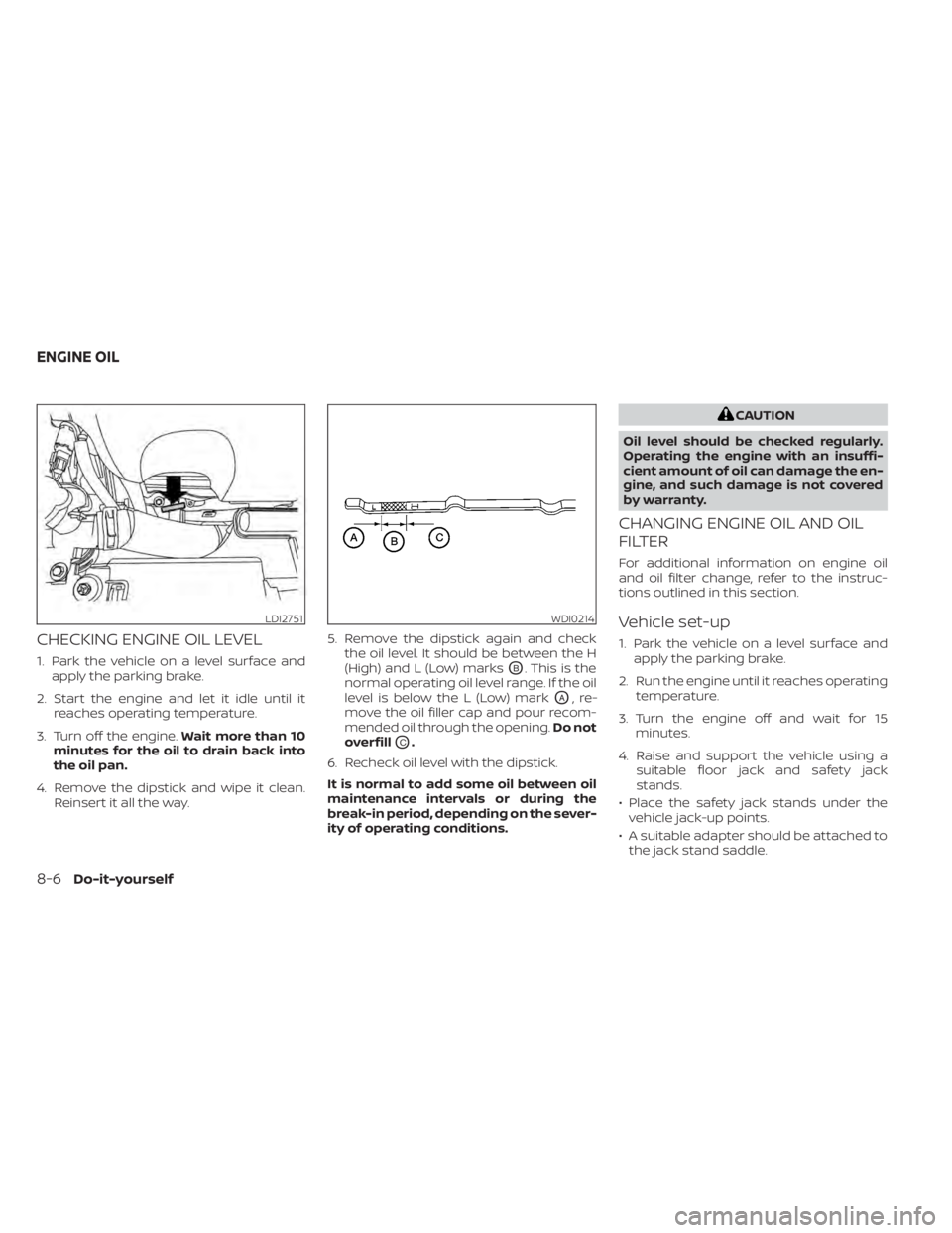
CHECKING ENGINE OIL LEVEL
1. Park the vehicle on a level surface andapply the parking brake.
2. Start the engine and let it idle until it reaches operating temperature.
3. Turn off the engine. Wait more than 10
minutes for the oil to drain back into
the oil pan.
4. Remove the dipstick and wipe it clean. Reinsert it all the way. 5. Remove the dipstick again and check
the oil level. It should be between the H
(High) and L (Low) marksOB. This is the
normal operating oil level range. If the oil
level is below the L (Low) mark
OA,re-
move the oil filler cap and pour recom-
mended oil through the opening. Do not
overfill
OC.
6. Recheck oil level with the dipstick.
It is normal to add some oil between oil
maintenance intervals or during the
break-in period, depending on the sever-
ity of operating conditions.
CAUTION
Oil level should be checked regularly.
Operating the engine with an insuffi-
cient amount of oil can damage the en-
gine, and such damage is not covered
by warranty.
CHANGING ENGINE OIL AND OIL
FILTER
For additional information on engine oil
and oil filter change, refer to the instruc-
tions outlined in this section.
Vehicle set-up
1. Park the vehicle on a level surface and apply the parking brake.
2. Run the engine until it reaches operating temperature.
3. Turn the engine off and wait for 15 minutes.
4. Raise and support the vehicle using a suitable floor jack and safety jack
stands.
• Place the safety jack stands under the vehicle jack-up points.
• A suitable adapter should be attached to the jack stand saddle.
LDI2751WDI0214
ENGINE OIL
8-6Do-it-yourself
Page 384 of 476
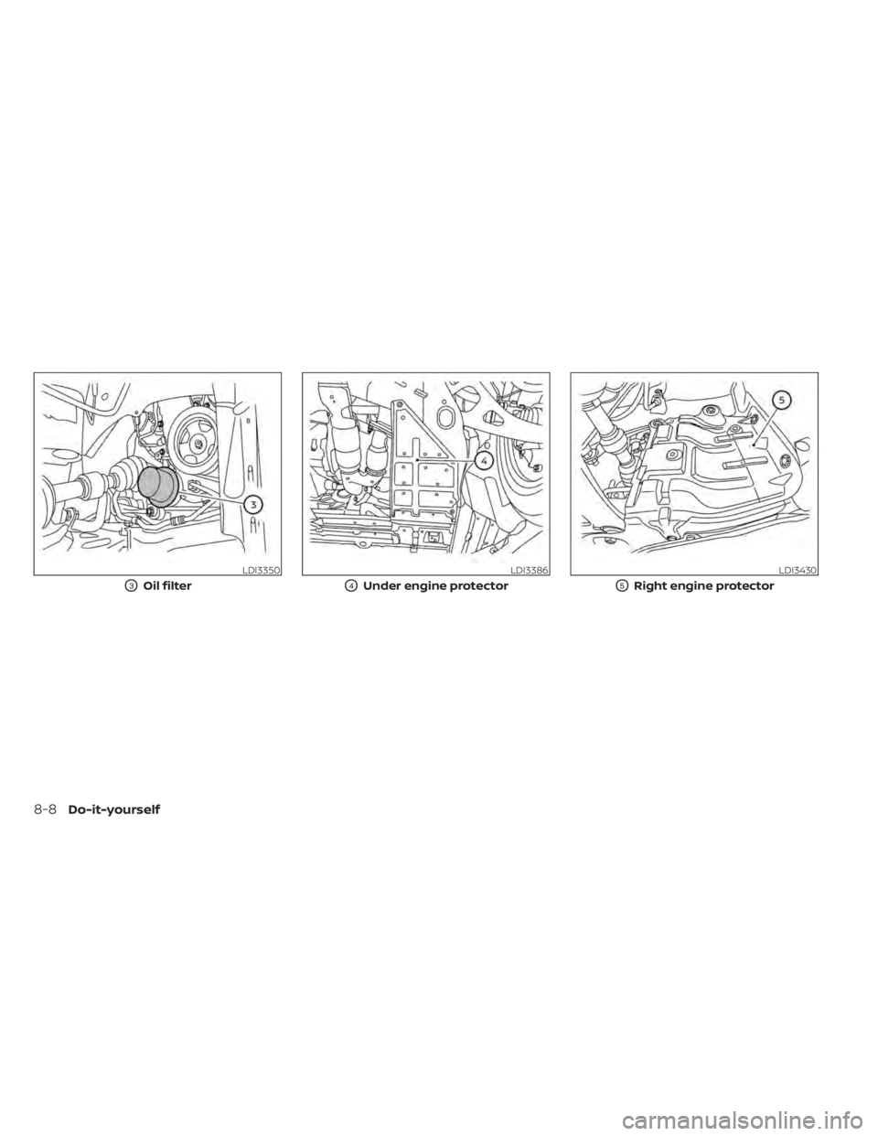
LDI3350
O3Oil filter
LDI3386
O4Under engine protector
LDI3430
O5Right engine protector
8-8Do-it-yourself
Page 385 of 476
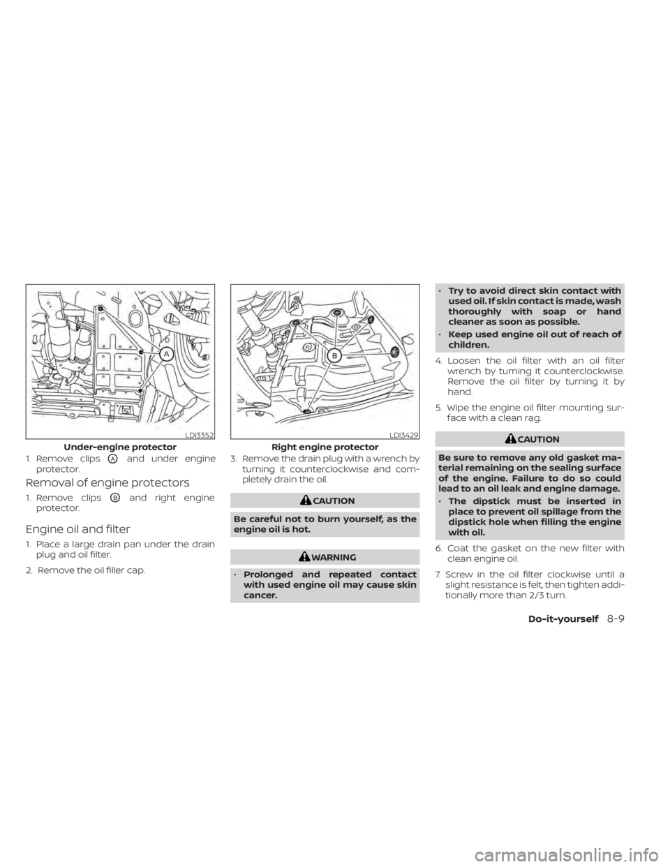
Removal of engine protectors
1. Remove clipsOBand right engine
protector.
Engine oil and filter
1. Place a large drain pan under the drain plug and oil filter.
2. Remove the oil filler cap. 3. Remove the drain plug with a wrench by
turning it counterclockwise and com-
pletely drain the oil.
CAUTION
Be careful not to burn yourself, as the
engine oil is hot.
WARNING
• Prolonged and repeated contact
with used engine oil may cause skin
cancer. •
Try to avoid direct skin contact with
used oil. If skin contact is made, wash
thoroughly with soap or hand
cleaner as soon as possible.
• Keep used engine oil out of reach of
children.
4. Loosen the oil filter with an oil filter wrench by turning it counterclockwise.
Remove the oil filter by turning it by
hand.
5. Wipe the engine oil filter mounting sur- face with a clean rag.
CAUTION
Be sure to remove any old gasket ma-
terial remaining on the sealing surface
of the engine. Failure to do so could
lead to an oil leak and engine damage.
• The dipstick must be inserted in
place to prevent oil spillage from the
dipstick hole when filling the engine
with oil.
6. Coat the gasket on the new filter with clean engine oil.
7. Screw in the oil filter clockwise until a slight resistance is felt, then tighten addi-
tionally more than 2/3 turn.LDI3352
Under-engine protector
1. Remove clips
OAand under engine
protector.
LDI3429
Right engine protector
Do-it-yourself8-9
Page 386 of 476
Oil filter tightening torque:11 to 15 f t-lb (14.7 to 20.6 N·m)
8. Clean and re-install the drain plug with a new washer. Securely tighten the drain
plug with a wrench. Do not use exces-
sive force.
Drain plug tightening torque: 22 to 29 f t-lb (29.4 to 39.2 N·m)
9. Refill the engine with the recommended oil through the oil filler opening, and in-
stall the oil filler cap securely.
For additional information about drain and
refill capacity, see “Recommended fluids/
lubricants and capacities” (P. 10-2). The
drain and refill capacity depends on the oil
temperature and drain time. Use these
specifications for reference only. Always
use the dipstick to determine the proper
amount of oil in the engine.
10. Start the engine and check for leakage around the drain plug and the oil filter.
Correct as required. Turn the engine off
and wait more than 15 minutes. Check
the oil level with the dipstick. Add en-
gine oil if necessary.Af ter the operation
1. Reinstall engine protectors in reverse or-der of removal.
2. Lower the vehicle carefully to the ground.
3. Reset oil and oil filter maintenance re- minder. For additional information, see
“Vehicle information display” (P. 2-17).
• Dispose of waste oil and filter properly.
• Check your local regulations.
CAUTION
• NISSAN recommends using Genuine
NISSAN CVT Fluid NS-3 (or equiva-
lent) ONLY in NISSAN CVTs. Do not mix
with other fluids.
• Do not use Automatic Transmission
Fluid (ATF) or manual transmission
fluid in a NISSAN CVT, as it may dam-
age the CVT. Damage caused by the
use of fluids other than as recom-
mended is not covered under
NISSAN's New Vehicle Limited War-
ranty outlined in your Warranty Infor-
mation Booklet.
• Using fluids that are not equivalent
to Genuine NISSAN CVT Fluid NS-3
may also damage the CVT. Damage
caused by the use of fluids other than
as recommended is not covered un-
der NISSAN's New Vehicle Limited
Warranty outlined in your Warranty
Information Booklet.
When checking or replacement of CVT fluid
is required, it is recommended that you visit
a NISSAN dealer for this service.
CONTINUOUSLY VARIABLE
TRANSMISSION (CVT) FLUID
8-10Do-it-yourself
Page 420 of 476
NOTE:
NISSAN does not advocate the use of
non-OEM approved af termarket flush-
ing systems and strongly advises
against performing these services on a
NISSAN product. Many of the af termar-
ket flushing systems use non-OEM ap-
proved chemicals or solvents, the use of
which has not been validated by NISSAN.
For recommended fuel, lubricants, fluids,
grease, and refrigerant, see “Recom-
mended fluids/lubricants and capaci-
ties” (P. 10-2).
EMISSION CONTROL SYSTEM
MAINTENANCE:
Drive belts*:Check engine drive belts for
wear, fraying or cracking and for proper
tension. Replace any damaged drive belts.
Engine air filter: Replace at specified inter-
vals. When driving for prolonged periods in
dusty conditions, check/replace the filter
more frequently.
Engine coolant*: Replace coolant at the
specified interval. When adding or replac-
ing coolant, be sure to use only Genuine
NISSAN Long Life Antifreeze/Coolant (blue)
or equivalent with the proper mixture. (For additional information on the proper mix-
ture for your area, see “Engine cooling sys-
tem” (P. 8-5.)
NOTE: Mixing any other type of coolant or
the use of non-distilled water may reduce
the recommended service interval of the
coolant.
Engine oil and oil filter:
Replace engine oil
and oil filter at the specified intervals. For
recommended oil grade and viscosity, see
“Recommended fluids/lubricants and ca-
pacities” (P. 10-2).
Fuel lines*: Check the fuel hoses, piping
and connections for leaks, looseness, or
deterioration. Tighten connections or re-
place parts as necessary.
Spark plugs: Replace at specified intervals.
Install new plugs of the same type as origi-
nally equipped.
CHASSIS AND BODY
MAINTENANCE:
Brake lines and cables: Visually inspect for
proper installation. Check for chafing,
cracks, deterioration, and signs of leaking.
Replace any deteriorated or damaged
parts immediately. Brake pads and rotors:
Check for wear, de-
terioration and fluid leaks. Replace any dete-
riorated or damaged parts immediately.
Exhaust system: Visually inspect the ex-
haust pipes, muffler and hangers for leaks,
cracks, deterioration, and damage. Tighten
connections or replace parts as necessary.
In-cabin microfilter: Replace at specified
intervals. When driving for prolonged peri-
ods in dusty conditions, replace the filter
more frequently.
Steering gear and linkage, axle and sus-
pension parts, drive shaf t boots: Check
for damage, looseness, and leakage of oil
or grease. Under severe driving conditions,
inspect more frequently.
Tire rotation: Rotate tires at the specified
interval shown in the maintenance sched-
ule. When rotating tires, check for damage
and uneven wear. Replace if necessary.
Transmission fluid/oil: Visually inspect for
signs of leakage at specified intervals.
If using a car-top carrier, or driving on rough
or muddy roads, replace the CVT fluid every
60,000 miles (96,000 km) or request the
dealer to inspect the fluid deterioration data
using a CONSULT. If the deterioration data is
more than 210000, replace the CVT fluid.
9-6Maintenance and schedules
Page 422 of 476

3.5L 6 CYLINDER (VQ35DE engine
model)
The following shows the maintenance
schedule.
Choose the maintenance schedule
needed based on your vehicle driving
conditions.
Af ter 120,000 miles (192,000 km)/96
months, continue maintenance at the
same mileage/time interval.
5,000 miles/(8,000 km)/6 months
Perform at number of miles, kilometers or
months, whichever comes first.
Standard maintenance:
Not Applicable. Proceed to next interval
Severe maintenance:
Inspections:
• Brake pads & rotors
• Exhaust system
• Front drive shaf t boots
• Steering gear & linkage
• Axle & suspension parts
• Horn, lights, signals, wipers, rear hatch/hood lif t supports
• All fluids inspected (engine, wiper, brake, power steering, coolant)
• Hose inspections
• Engine air filter
• Suspension components (shocks, sub- frame, tie rods)
• Battery terminals and cables, battery test
• Tire pressure, treadwear and depth
Essential:
• Replace engine oil & filter
7,500 miles/(12,000 km)/6 months
Perform at number of miles, kilometers or
months, whichever comes first.
Standard maintenance:
Inspections:
• Horn, lights, signals, wipers, rear hatch/ hood lif t supports
• All fluids inspected (engine, wiper, brake, power steering, coolant)
• Hose inspections
• Engine air filter
• Suspension components (shocks, sub- frame, tie rods)
• Battery terminals and cables, battery test
• Tire pressure, treadwear and depth
Essential:
• Replace engine oil & filter
• Tire rotation
Severe maintenance:
Not Applicable. Proceed to next interval
9-8Maintenance and schedules