service indicator NISSAN MAXIMA 2023 User Guide
[x] Cancel search | Manufacturer: NISSAN, Model Year: 2023, Model line: MAXIMA, Model: NISSAN MAXIMA 2023Pages: 494, PDF Size: 5.7 MB
Page 136 of 494
•The timing of switching the low
beam and high beam may change
under the following situations.
– The brightness of the headlights
of the oncoming vehicle or leading
vehicle.
– The movement and direction of
the oncoming vehicle and the
leading vehicle.
– When only one light on the on-
coming vehicle or the leading ve-
hicle is illuminated.
– When the oncoming vehicle or the
leading vehicle is a two-wheeled
vehicle.
– Road conditions (incline, curve,
the road surface, etc.).
– The number of passengers and
the amount of luggage.
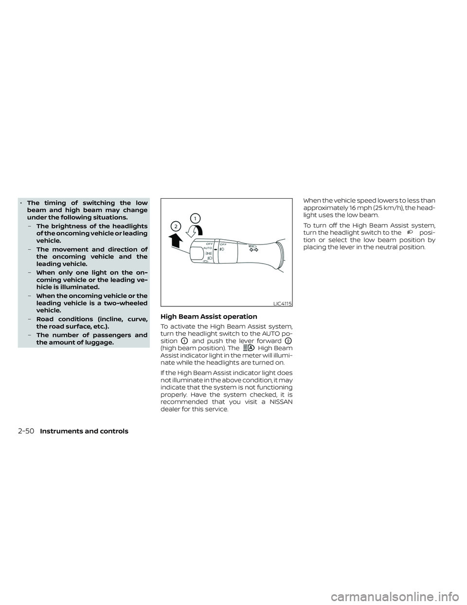
High Beam Assist operation
To activate the High Beam Assist system,
turn the headlight switch to the AUTO po-
sition
O1and push the lever forwardO2
(high beam position). TheHigh Beam
Assist indicator light in the meter will illumi-
nate while the headlights are turned on.
If the High Beam Assist indicator light does
not illuminate in the above condition, it may
indicate that the system is not functioning
properly. Have the system checked, it is
recommended that you visit a NISSAN
dealer for this service. When the vehicle speed lowers to less than
approximately 16 mph (25 km/h), the head-
light uses the low beam.
To turn off the High Beam Assist system,
turn the headlight switch to the
posi-
tion or select the low beam position by
placing the lever in the neutral position.
LIC4115
2-50Instruments and controls
Page 141 of 494

•When cleaning the seat, never use
gasoline, benzine, thinner, or any simi-
lar materials.
• If any malfunctions are found or the
climate-controlled seat does not op-
erate, turn the switch off and have
the system checked. It is recom-
mended that you visit a NISSAN
dealer for this service.
The front seats are warmed by built-in
heaters.
1. Start the engine.
2. Push the LO or HI position of the switch,as desired. The indicator light in the
switch will illuminate.
The heater is controlled by a thermostat,
automatically turning the heater on and
off. The indicator light will remain on as
long as the switch is on.
3. When the seat is warmed or before you leave the vehicle, be sure to turn the
switch off.
WARNING
Do not use or allow occupants to use
the seat heater if you or the occupants
cannot monitor elevated seat tem-
peratures or have an inability to feel
pain in body parts that contact the
seat. Use of the seat heater by such
people could result in serious injury.
CAUTION
• The battery could run down if the
seat heater is operated while the en-
gine is not running.
• Do not use the seat heater for ex-
tended periods or when no one is
using the seat.
•
Do not put anything on the seat which
insulates heat, such as a blanket,
cushion, seat cover, etc. Otherwise, the
seat may become overheated.
• Do not place anything hard or heavy
on the seat or pierce it with a pin or
similar object. This may result in
damage to the heater.
• Any liquid spilled on the heated seat
should be removed immediately with
a dry cloth.
LIC3037
HEATED SEAT SWITCHES (if so
equipped)
Instruments and controls2-55
Page 146 of 494
– It may not be possible to make anemergency call depending on the
severity of a collision and/or
emergency.
• Park the vehicle in a safe location and
set the parking brake before operat-
ing the Emergency Call (SOS) button.
• Only use this service in case of an
emergency. There may be a penalty
for inappropriate use of the service.
• Radio waves could adversely affect
electric medical equipment. Indi-
viduals who use a pacemaker should
contact the device manufacturer re-
garding any possible effects before
using the system.
• The TCU (Telematics Control Unit) an-
tenna is installed inside the upper
central part of the instrument panel.
An occupant should not get any
closer to the antenna than specified
by the pacemaker manufacturer. The
radio waves from the TCU antenna
may adversely affect the operation
of the pacemaker while using the
NissanConnect® Services.
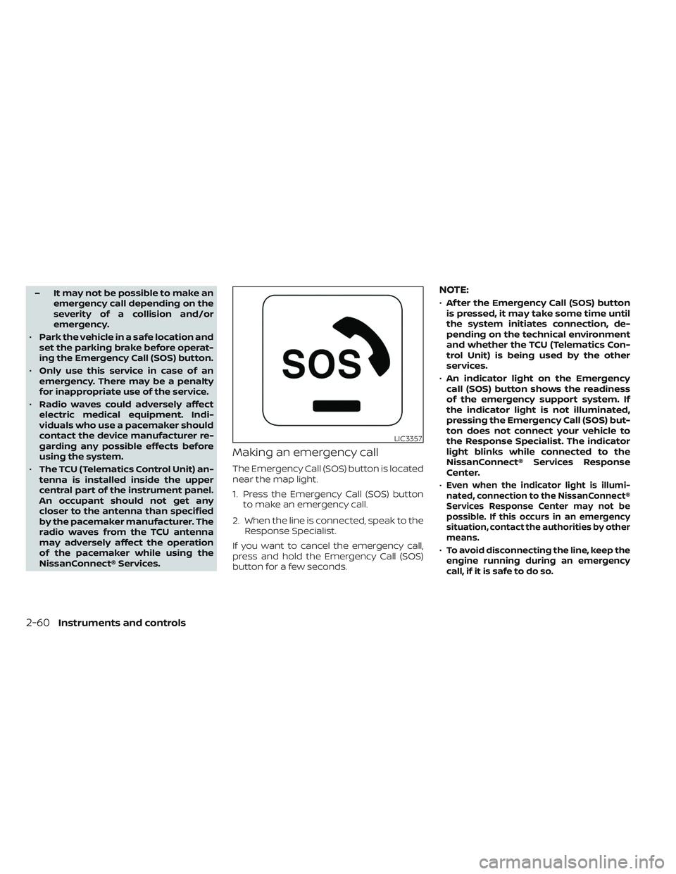
Making an emergency call
The Emergency Call (SOS) button is located
near the map light.
1. Press the Emergency Call (SOS) button to make an emergency call.
2. When the line is connected, speak to the Response Specialist.
If you want to cancel the emergency call,
press and hold the Emergency Call (SOS)
button for a few seconds.
NOTE:
• Af ter the Emergency Call (SOS) button
is pressed, it may take some time until
the system initiates connection, de-
pending on the technical environment
and whether the TCU (Telematics Con-
trol Unit) is being used by the other
services.
• An indicator light on the Emergency
call (SOS) button shows the readiness
of the emergency support system. If
the indicator light is not illuminated,
pressing the Emergency Call (SOS) but-
ton does not connect your vehicle to
the Response Specialist. The indicator
light blinks while connected to the
NissanConnect® Services Response
Center.
•
Even when the indicator light is illumi-
nated, connection to the NissanConnect®
Services Response Center may not be
possible. If this occurs in an emergency
situation, contact the authorities by other
means.
•To avoid disconnecting the line, keep the
engine running during an emergency
call,ifitissafetodoso.
LIC3357
2-60Instruments and controls
Page 191 of 494
–Keep the pump nozzle in contact
with the container while you are
filling it.
– Use only approved portable fuel
containers for flammable liquid.
CAUTION
• Do not use a fuel containing more
than 15% ethanol in your vehicle. For
additional information, see “Fuel rec-
ommendation” (P. 10-4).
• The Loose Fuel Cap warning will ap-
pear if the fuel-filler cap is not prop-
erly tightened. It may take a few driv-
ing trips for the message to be
displayed. Failure to tighten the fuel-
filler cap properly af ter the Loose
Fuel Cap warning appears may cause
the
Malfunction Indicator Light
(MIL) to illuminate. •
Failure to tighten the fuel-filler cap
properly may cause the
Mal-
function Indicator Light (MIL) to illu-
minate. If the
light illuminates
because the fuel-filler cap is loose or
missing, tighten or install the cap and
continue to drive the vehicle. The
light should turn off af ter a few
driving trips. If thelight does not
turn off af ter a few driving trips, have
the vehicle inspected. It is recom-
mended that you visit a NISSAN
dealer for this service.
•
For additional information, see “Mal-
function Indicator Light (MIL)” (P. 2-13).
• If fuel is spilled on the vehicle body,
flush it away with water to avoid
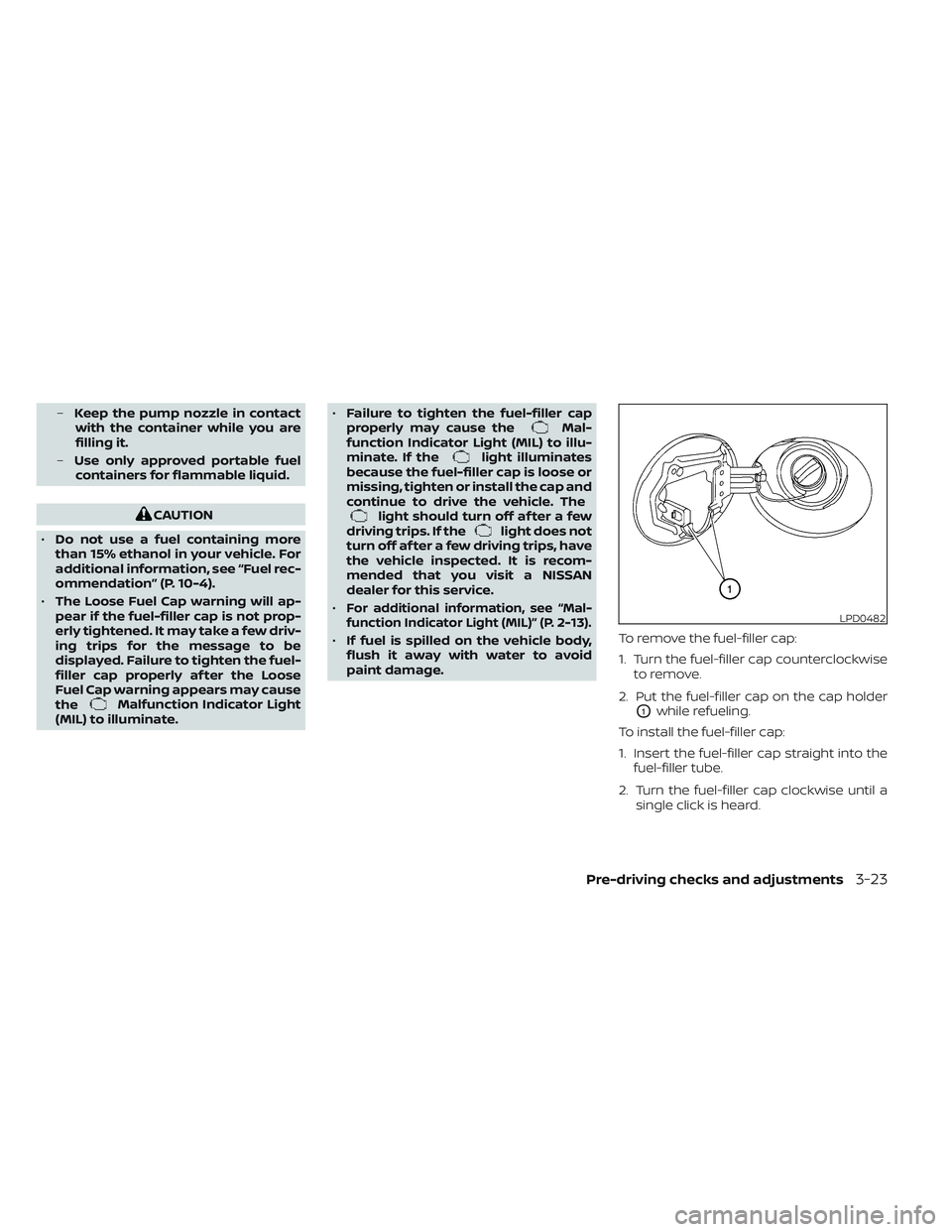
paint damage. To remove the fuel-filler cap:
1. Turn the fuel-filler cap counterclockwise
to remove.
2. Put the fuel-filler cap on the cap holder
O1while refueling.
To install the fuel-filler cap:
1. Insert the fuel-filler cap straight into the fuel-filler tube.
2. Turn the fuel-filler cap clockwise until a single click is heard.
LPD0482
Pre-driving checks and adjustments3-23
Page 239 of 494
•Do not stop or park the vehicle over
flammable materials such as dry
grass, waste paper or rags. They may
ignite and cause a fire.
CAUTION
• Do not use leaded gasoline. Deposits
from leaded gasoline will seriously
reduce the three-way catalyst's abil-
ity to help reduce exhaust pollutants.
• Keep your engine tuned up. Malfunc-
tions in the ignition, fuel injection, or
electrical systems can cause overrich
fuel flow into the three-way catalyst,
causing it to overheat. Do not keep
driving if the engine misfires, or if
noticeable loss of performance or
other unusual operating conditions
are detected. Have the vehicle in-
spected promptly. It is recom-
mended that you visit a NISSAN
dealer for this service.
• Avoid driving with an extremely low
fuel level. Running out of fuel could
cause the engine to misfire, damag-
ing the three-way catalyst.
• Do not race the engine while warm-
ing it up. •
Do not push or tow your vehicle to
start the engine.
TIRE PRESSURE MONITORING
SYSTEM (TPMS)
Each tire, including the spare (if provided),
should be checked monthly when cold and
inflated to the inflation pressure recom-
mended by the vehicle manufacturer on
the vehicle placard or tire inflation pressure
label. (If your vehicle has tires of a different
size than the size indicated on the vehicle
placard or tire inflation pressure label, you
should determine the proper tire inflation
pressure for those tires.)
As an added safety feature, your vehicle
has been equipped with a Tire Pressure
Monitoring System (TPMS) that illuminates
a low tire pressure telltale when one or
more of your tires is significantly under-
inflated. Accordingly, when the low tire
pressure telltale illuminates, you should
stop and check all your tires as soon as
possible, and inflate them to the proper
pressure. Driving on a significantly under-
inflated tire causes the tire to overheat and
can lead to tire failure. Under-inflation also
reduces fuel efficiency and tire tread life,
and may affect the vehicle’s handling and
stopping ability. Please note that the TPMS is not a substi-
tute for proper tire maintenance, and it is
the driver’s responsibility to maintain cor-
rect tire pressure, even if under-inflation
has not reached the level to trigger illumi-
nation of the TPMS low tire pressure telltale.
Your vehicle has also been equipped with a
TPMS malfunction indicator to indicate
when the system is not operating properly.
The TPMS malfunction indicator is com-
bined with the low tire pressure telltale.
When the system detects a malfunction,
the telltale will flash for approximately one
minute and then remain continuously illu-
minated. This sequence will continue upon
subsequent vehicle start-ups as long as
the malfunction exists. When the malfunc-
tion indicator is illuminated, the system
may not be able to detect or signal low tire
pressure as intended. TPMS malfunctions
may occur for a variety of reasons, includ-
ing the installation of replacement or alter-
nate tires or wheels on the vehicle that
prevent the TPMS from functioning prop-
erly. Always check the TPMS malfunction
telltale af ter replacing one or more tires or
wheels on your vehicle to ensure that the
replacement or alternate tires and wheels
allow the TPMS to continue to function
properly.
Starting and driving5-5
Page 254 of 494
•When this situation occurs, the Con-
tinuously Variable Transmission (CVT)
position indicator will blink and the
chime will sound.
• In the manual shif t mode, the trans-
mission may shif t up automatically to a
higher range than selected if the en-
gine speed is too high. When the ve-
hicle speed decreases, the transmis-
sion automatically shif ts down and
shif ts to 1st gear before the vehicle
comes to a stop.
• CVT operation is limited to automatic drive mode when CVT fluid temperature
is extremely low even if manual shif t
mode is selected. This is not a malfunc-
tion. When CVT fluid warms up, manual
mode can be selected.
• When the CVT fluid temperature is high, the shif t range may upshif t in lower rpm
than usual. This is not a malfunction.
Shif t lock release
If the battery charge is low or discharged,
the shif t lever may not be moved from the
P (Park) position even with the brake pedal
depressed and the shif t lever button
pressed.
It will be necessary to jump start or have
your battery charged. For additional infor-
mation, see “Jump starting” (P. 6-9). It is rec-
ommended that you visit a NISSAN dealer
or a professional towing service. To move the shif t lever, complete the fol-
lowing procedure:
1. Push the ignition switch to the LOCK
position.
2. Apply the parking brake.
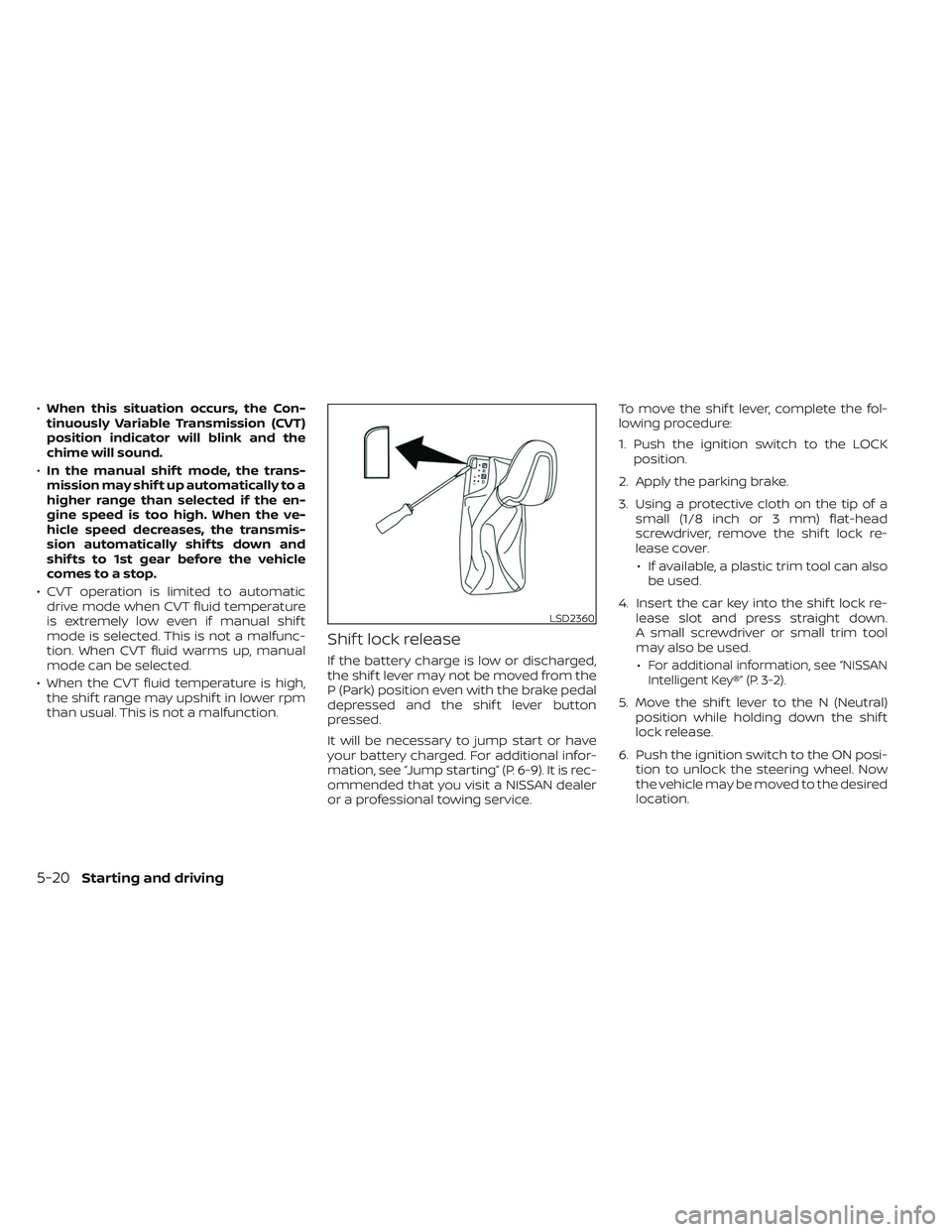
3. Using a protective cloth on the tip of a small (1/8 inch or 3 mm) flat-head
screwdriver, remove the shif t lock re-
lease cover.
• If available, a plastic trim tool can also be used.
4. Insert the car key into the shif t lock re- lease slot and press straight down.
A small screwdriver or small trim tool
may also be used.
•For additional information, see “NISSAN
Intelligent Key®” (P. 3-2).
5. Move the shif t lever to the N (Neutral) position while holding down the shif t
lock release.
6. Push the ignition switch to the ON posi- tion to unlock the steering wheel. Now
the vehicle may be moved to the desired
location.
LSD2360
5-20Starting and driving
Page 255 of 494
If the shif t lever cannot be moved out of P
(Park), have the transmission checked as
soon as possible. It is recommended that
you visit a NISSAN dealer for this service.
CAUTION
Make sure to take extra care during the
removal of the shif t lock cap as this
part is easily damaged.
WARNING
If the shif t lever cannot be moved from
the P (Park) position while the engine is
running and the brake pedal is de-
pressed, the stop lights may not work.
Malfunctioning stop lights could cause
an accident injuring yourself and
others.
Accelerator downshif t
— in D (Drive) position and manual
shif t mode
For passing or hill climbing, depress the
accelerator pedal to the floor. This shif ts
the transmission down into lower range,
depending on the vehicle speed.
High fluid temperature protection
mode
This transmission has a high fluid tem-
perature protection mode. If the fluid tem-
perature becomes too high (for example,
when climbing steep grades in high tem-
peratures with heavy loads, such as when
towing a trailer), engine power and, under
some conditions, vehicle speed will be
decreased automatically to reduce the
chance of transmission damage. Vehicle
speed can be controlled with the accelera-
tor pedal, but the engine and vehicle speed
may be limited.
Fail-safe
If the vehicle is driven under extreme
conditions, such as excessive wheel
spinning and subsequent hard braking,
the fail-safe system may be activated.
The Malfunction Indicator Light (MIL)
may come on to indicate the fail-safe
mode is activated. For additional infor-
mation, see “Malfunction Indicator Light
(MIL)” (P. 2-13). This will occur even if all
electrical circuits are functioning prop-
erly. In this case, place the ignition switch
in the OFF position and wait for 10 sec- onds. Then place the ignition switch
back in the ON position. The vehicle
should return to its normal operating
condition. If it does not return to its nor-
mal operating condition, have the trans-
mission checked and repaired, if neces-
sary. It is recommended that you visit a
NISSAN dealer for this service.
WARNING
When the high fluid temperature pro-
tection mode or fail-safe operation oc-
curs, vehicle speed may be gradually
reduced. The reduced speed may be
lower than other traffic, which could in-
crease the chance of a collision. Be es-
pecially careful when driving. If neces-
sary, pull to the side of the road at a safe
place and allow the transmission to re-
turn to normal operation, or have it re-
paired if necessary.
Starting and driving5-21
Page 264 of 494
–When a sudden change in bright-
ness occurs. (For example, when
the vehicle enters or exits a tunnel
or under a bridge.)
SYSTEM TEMPORARILY
UNAVAILABLE
If the vehicle is parked in direct sunlight
under high temperature conditions (over
approximately 104°F [40°C]) and then
started, the LDW system may be deacti-
vated automatically and the following
message will appear in the vehicle infor-
mation display: “Unavailable: High Cabin
Temperature.” In this instance the LDW indi-
cator (white) will blink.
When the interior temperature is reduced,
the LDW system will resume operating
automatically.
The LDW system is not designed to warn
under the following conditions:
• When you operate the lane change signal and change traveling lanes in the direc-
tion of the signal. (The LDW system will
become operable again approximately
2 seconds af ter the lane change signal is
turned off.)
• When the vehicle speed lowers to less than approximately 37 mph (60 km/h). Af ter the above conditions have finished
and the necessary operating conditions
are satisfied, the LDW functions will resume.
SYSTEM MALFUNCTION
If the LDW system malfunctions, it will can-
cel automatically. The LDW indicator (or-
ange) will illuminate in the display. If the
LDW indicator (orange) illuminates in the
display, pull off the road to a safe location
and stop the vehicle. Turn the engine/
motor off and restart the engine/motor.
If the LDW indicator (orange) continues to
illuminate, have the LDW system checked. It
is recommended that you visit a NISSAN
dealer for this service.
SYSTEM MAINTENANCE
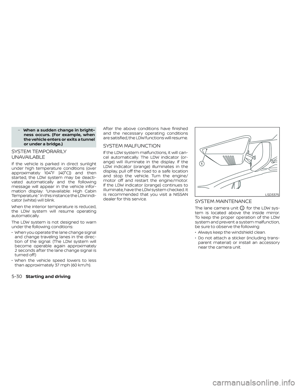
The lane camera unitO1for the LDW sys-
tem is located above the inside mirror.
To keep the proper operation of the LDW
system and prevent a system malfunction,
be sure to observe the following:
• Always keep the windshield clean.
• Do not attach a sticker (including trans- parent material) or install an accessory
near the camera unit.
LSD3375
5-30Starting and driving
Page 270 of 494
![NISSAN MAXIMA 2023 User Guide • “Unavailable Road is Slippery”:When the VDC system (except Traction
Control System [TCS] function) or ABS
operates.
• “Currently Unavailable”: When the VDC system is turned off.
Action t NISSAN MAXIMA 2023 User Guide • “Unavailable Road is Slippery”:When the VDC system (except Traction
Control System [TCS] function) or ABS
operates.
• “Currently Unavailable”: When the VDC system is turned off.
Action t](/img/5/56781/w960_56781-269.png)
• “Unavailable Road is Slippery”:When the VDC system (except Traction
Control System [TCS] function) or ABS
operates.
• “Currently Unavailable”: When the VDC system is turned off.
Action to take:
When the above conditions no longer exist,
turn off the I-LI system. Push the dynamic
driver assistance switch again to turn the
I-LI system back on.
Temporary disabled status at high
temperature:
If the vehicle is parked in direct sunlight
under high temperature conditions (over
approximately 104°F [40°C]) and then the
I-LI system is turned on, the I-LI system
may be deactivated automatically and the
following message will appear on the ve-
hicle information display: “Unavailable: High
Cabin Temperature.” When the interior
temperature is reduced, the system will re-
sume operating automatically.SYSTEM MALFUNCTION
If the I-LI system malfunctions, it will cancel
automatically. The LDW indicator (orange)
will illuminate in the display. If the LDW indi-
cator (orange) illuminates in the display,
pull off the road to a safe location and stop
the vehicle. Turn the engine/motor off and
restart the engine/motor. If the LDW indica-
tor (orange) continues to illuminate, have
the I-LI system checked. It is recom-
mended that you visit a NISSAN dealer for
this service.
SYSTEM MAINTENANCE
The lane camera unitO1for the I-LI system
is located above the inside mirror. To keep
the proper operation of the I-LI system and
prevent a system malfunction, be sure to
observe the following:
• Always keep the windshield clean.
• Do not attach a sticker (including trans- parent material) or install an accessory
near the camera unit.
LSD3375
5-36Starting and driving
Page 280 of 494
Malfunction
If the BSW system malfunctions, it will turn
off automatically. The BSW/RCTA indicator
(orange) will appear in the vehicle informa-
tion display.
NOTE:
If the BSW system stops working, the
RCTA system will also stop working.
Action to take:
Stop the vehicle in a safe location, place the
vehicle in the P (Park) position, turn the en-
gine off and restart the engine. If the mes-
sage continues to appear, have the system
checked. It is recommended that you visit a
NISSAN dealer for this service.
SYSTEM MAINTENANCE
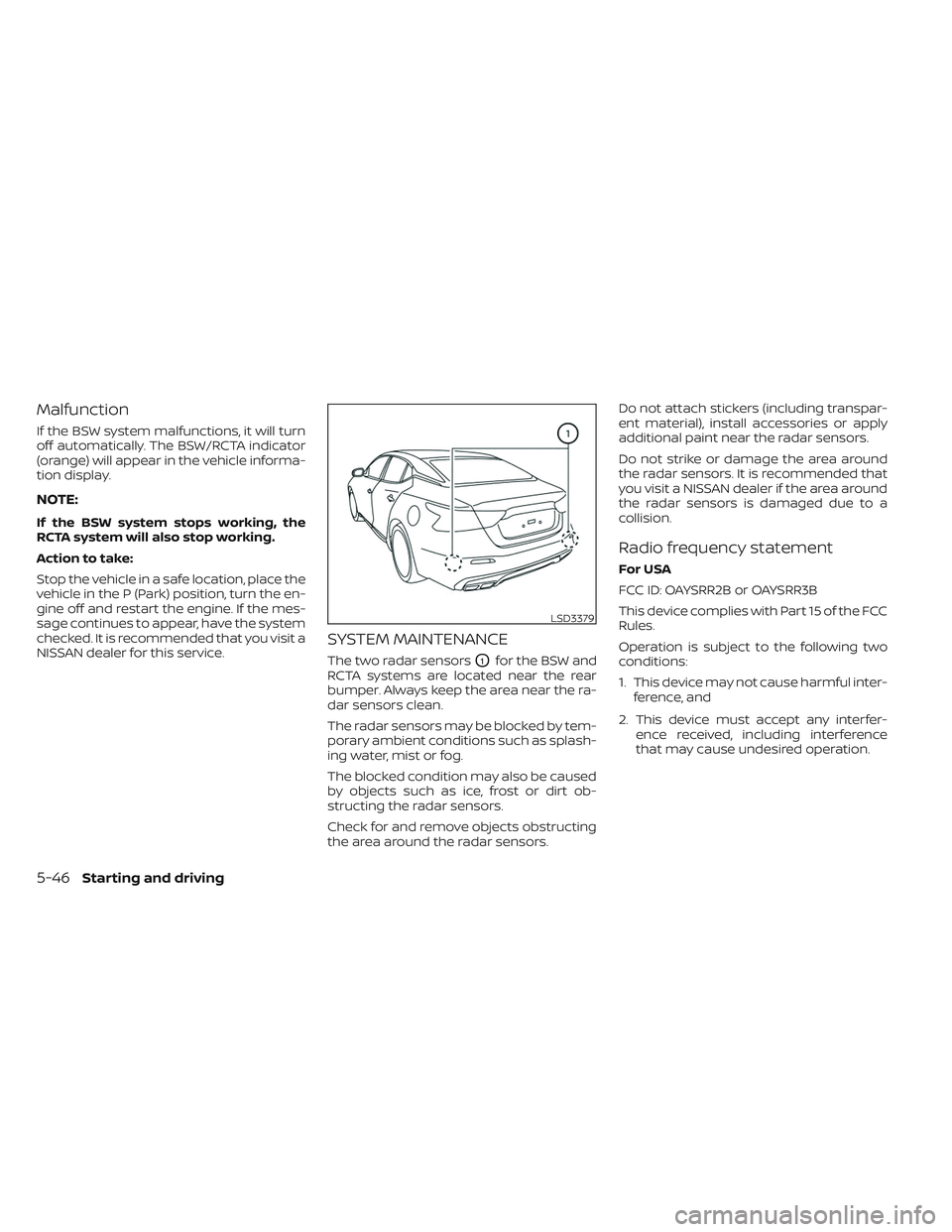
The two radar sensorsO1for the BSW and
RCTA systems are located near the rear
bumper. Always keep the area near the ra-
dar sensors clean.
The radar sensors may be blocked by tem-
porary ambient conditions such as splash-
ing water, mist or fog.
The blocked condition may also be caused
by objects such as ice, frost or dirt ob-
structing the radar sensors.
Check for and remove objects obstructing
the area around the radar sensors. Do not attach stickers (including transpar-
ent material), install accessories or apply
additional paint near the radar sensors.
Do not strike or damage the area around
the radar sensors. It is recommended that
you visit a NISSAN dealer if the area around
the radar sensors is damaged due to a
collision.
Radio frequency statement
For USA
FCC ID: OAYSRR2B or OAYSRR3B
This device complies with Part 15 of the FCC
Rules.
Operation is subject to the following two
conditions:
1. This device may not cause harmful inter-
ference, and
2. This device must accept any interfer- ence received, including interference
that may cause undesired operation.
LSD3379
5-46Starting and driving