open hood NISSAN NAVARA 2005 Repair User Guide
[x] Cancel search | Manufacturer: NISSAN, Model Year: 2005, Model line: NAVARA, Model: NISSAN NAVARA 2005Pages: 3171, PDF Size: 49.59 MB
Page 750 of 3171
BL-166
THEFT WARNING SYSTEM
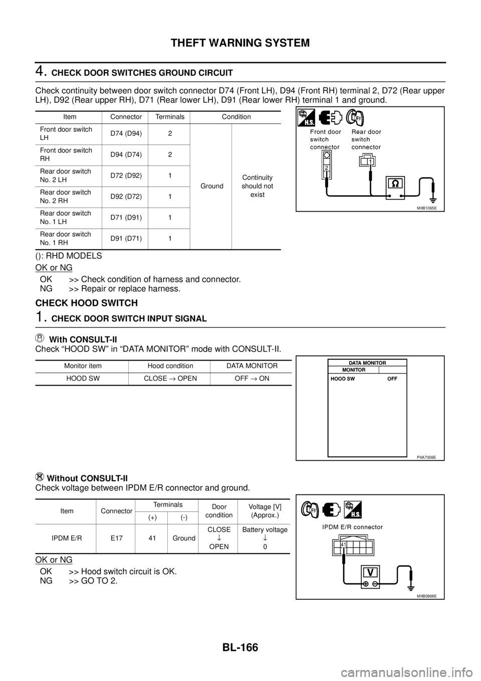
4.CHECK DOOR SWITCHES GROUND CIRCUIT
Check continuity between door switch connector D74 (Front LH), D94 (Front RH) terminal 2, D72 (Rear upper
LH), D92 (Rear upper RH), D71 (Rear lower LH), D91 (Rear lower RH) terminal 1 and ground.
(): RHD MODELS
OK or NG
OK >> Check condition of harness and connector.
NG >> Repair or replace harness.
CHECK HOOD SWITCH
1.CHECK DOOR SWITCH INPUT SIGNAL
With CONSULT-II
Check “HOOD SW” in “DATA MONITOR” mode with CONSULT-II.
Without CONSULT-II
Check voltage between IPDM E/R connector and ground.
OK or NG
OK >> Hood switch circuit is OK.
NG >> GO TO 2.
Item Connector Terminals Condition
Front door switch
LHD74 (D94) 2
GroundContinuity
should not
exist Front door switch
RHD94 (D74) 2
Rear door switch
No. 2 LHD72 (D92) 1
Rear door switch
No. 2 RHD92 (D72) 1
Rear door switch
No. 1 LHD71 (D91) 1
Rear door switch
No. 1 RHD91 (D71) 1
MIIB1065E
Monitor item Hood condition DATA MONITOR
HOOD SW CLOSE®OPEN OFF®ON
PIIA7006E
Item ConnectorTerminals
Door
conditionVoltage [V]
(Approx.)
(+) (-)
IPDM E/R E17 41 GroundCLOSE
¯
OPENBattery voltage
¯
0
MIIB0868E
Page 1018 of 3171
EC-38
TROUBLE DIAGNOSIS
Basic Inspection
EBS01KCV
Precaution:
Perform Basic Inspection without electrical or mechanical loads applied;
lHeadlamp switch is OFF.
lOn vehicles equipped with daytime light systems, set lighting switch to the 1st position to light
only small lamps.
lAir conditioner switch is OFF.
lHeater fan switch is OFF.
lRear defogger switch is OFF.
lHeat up switch is OFF.
lSteering wheel is in the straight-ahead position, etc.
1.INSPECTION START
1. Check service records for any recent repairs that may indicate a related incident.
2. Check the current need for scheduled maintenance, especially for fuel filter and air cleaner filter. Refer to
MA-8, "
PERIODIC MAINTENANCE".
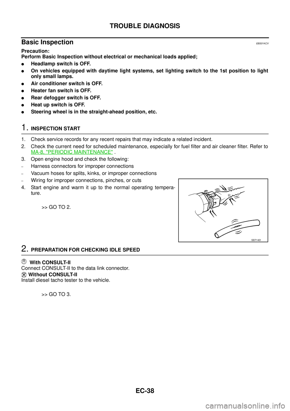
3. Open engine hood and check the following:
–Harness connectors for improper connections
–Vacuum hoses for splits, kinks, or improper connections
–Wiring for improper connections, pinches, or cuts
4. Start engine and warm it up to the normal operating tempera-
ture.
>> GO TO 2.
2.PREPARATION FOR CHECKING IDLE SPEED
With CONSULT-II
Connect CONSULT-II to the data link connector.
Without CONSULT-II
Install diesel tacho tester to the vehicle.
>> GO TO 3.
SEF142I
Page 1041 of 3171
TROUBLE DIAGNOSIS
EC-61
C
D
E
F
G
H
I
J
K
L
MA
EC
INSPECTION PROCEDURE
CAUTION:
If CONSULT-II is used with no connection of CONSULT-II CONVERTER, malfunctions might be
detected in self-diagnosis depending on control unit which carry out CAN communication.
1. Turn ignition switch OFF.
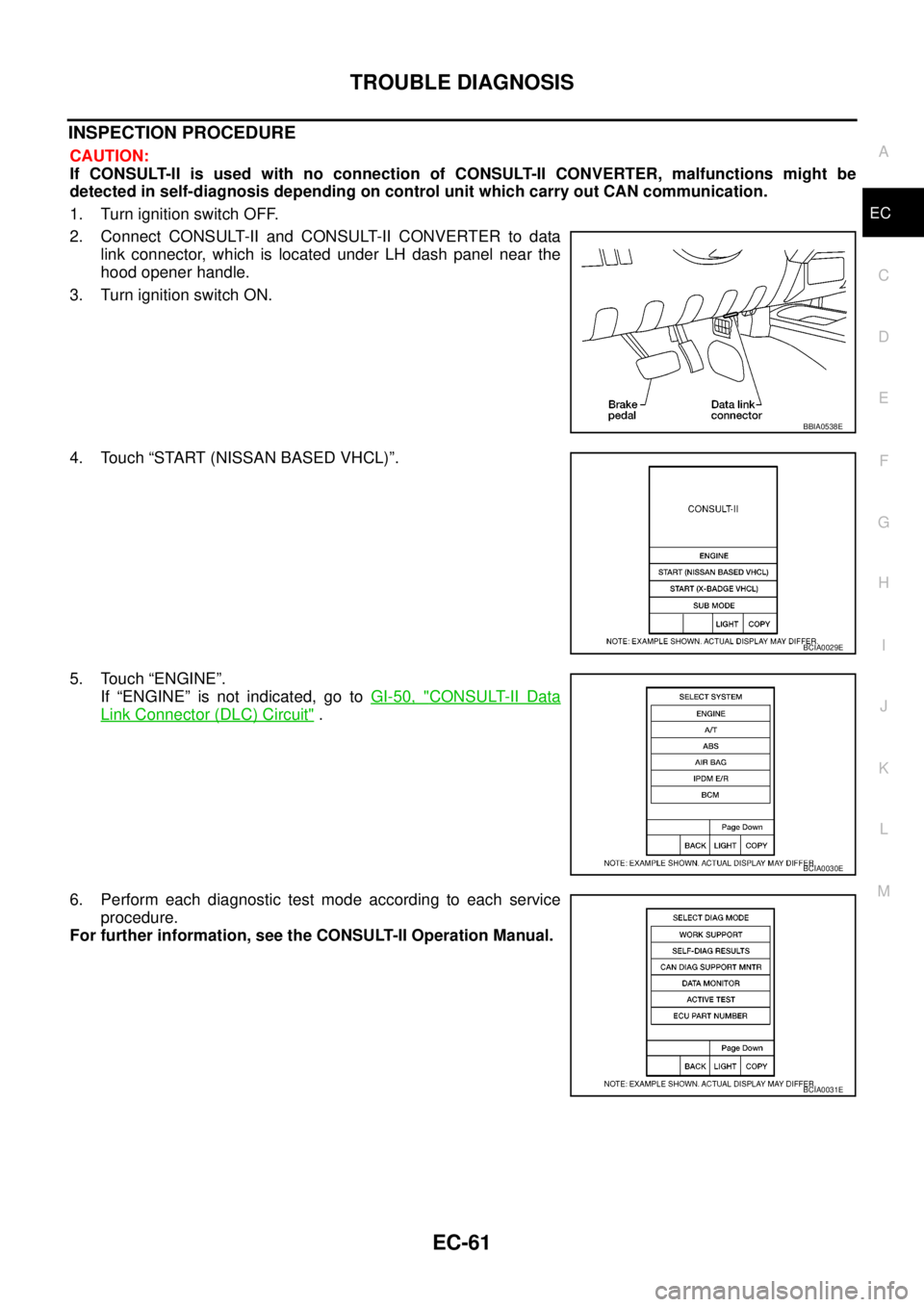
2. Connect CONSULT-II and CONSULT-II CONVERTER to data
link connector, which is located under LH dash panel near the
hood opener handle.
3. Turn ignition switch ON.
4. Touch “START (NISSAN BASED VHCL)”.
5. Touch “ENGINE”.
If “ENGINE” is not indicated, go toGI-50, "
CONSULT-II Data
Link Connector (DLC) Circuit".
6. Perform each diagnostic test mode according to each service
procedure.
For further information, see the CONSULT-II Operation Manual.
BBIA0538E
BCIA0029E
BCIA0030E
BCIA0031E
Page 2282 of 3171
GENERAL MAINTENANCE
MA-7
C
D
E
F
G
H
I
J
K
MA
B
MA
GENERAL MAINTENANCEPFP:00000
General MaintenanceELS001HT
General maintenance includes those items which should be checked during the normal day-to-day operation
of the vehicle. They are essential if the vehicle is to continue operating properly. The owners can perform the
checks and inspections themselves or they can have their NISSAN dealers do them for a nominal charge.
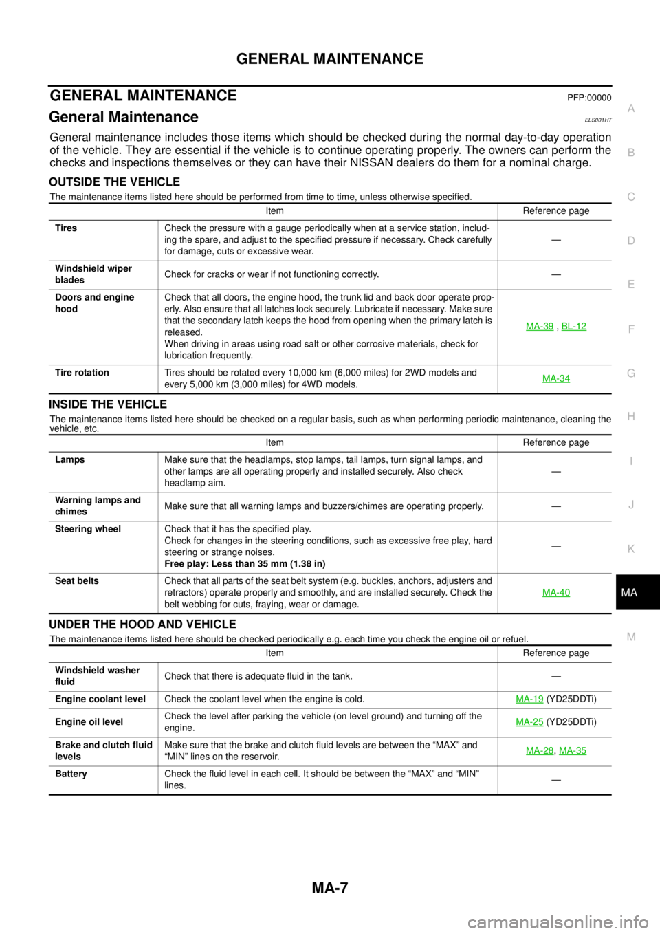
OUTSIDE THE VEHICLE
The maintenance items listed here should be performed from time to time, unless otherwise specified.
INSIDE THE VEHICLE
The maintenance items listed here should be checked on a regular basis, such as when performing periodic maintenance, cleaning the
vehicle, etc.
UNDER THE HOOD AND VEHICLE
The maintenance items listed here should be checked periodically e.g. each time you check the engine oil or refuel.Item Reference page
TiresCheck the pressure with a gauge periodically when at a service station, includ-
ing the spare, and adjust to the specified pressure if necessary. Check carefully
for damage, cuts or excessive wear.—
Windshield wiper
bladesCheck for cracks or wear if not functioning correctly. —
Doors and engine
hoodCheck that all doors, the engine hood, the trunk lid and back door operate prop-
erly. Also ensure that all latches lock securely. Lubricate if necessary. Make sure
that the secondary latch keeps the hood from opening when the primary latch is
released.
When driving in areas using road salt or other corrosive materials, check for
lubrication frequently.MA-39
,BL-12
Tire rotationTires should be rotated every 10,000 km (6,000 miles) for 2WD models and
every 5,000 km (3,000 miles) for 4WD models.MA-34
Item Reference page
LampsMake sure that the headlamps, stop lamps, tail lamps, turn signal lamps, and
other lamps are all operating properly and installed securely. Also check
headlamp aim.—
Warning lamps and
chimesMake sure that all warning lamps and buzzers/chimes are operating properly. —
Steering wheelCheck that it has the specified play.
Check for changes in the steering conditions, such as excessive free play, hard
steering or strange noises.
Free play: Less than 35 mm (1.38 in)—
Seat beltsCheck that all parts of the seat belt system (e.g. buckles, anchors, adjusters and
retractors) operate properly and smoothly, and are installed securely. Check the
belt webbing for cuts, fraying, wear or damage.MA-40
Item Reference page
Windshield washer
fluidCheck that there is adequate fluid in the tank. —
Engine coolant levelCheck the coolant level when the engine is cold.MA-19
(YD25DDTi)
Engine oil levelCheck the level after parking the vehicle (on level ground) and turning off the
engine.MA-25
(YD25DDTi)
Brake and clutch fluid
levelsMake sure that the brake and clutch fluid levels are between the “MAX” and
“MIN” lines on the reservoir.MA-28
,MA-35
BatteryCheck the fluid level in each cell. It should be between the “MAX” and “MIN”
lines.—
Page 2315 of 3171

MA-40
CHASSIS AND BODY MAINTENANCE
Checking Seat Belts, Buckles, Retractors, Anchors and Adjusters
ELS001J7
Check the seat belt buckles, webbing, retractors, anchors and adjusters. Replace any seat belt assembly as
necessary. Refer toSB-11, "
Seat Belt Inspection".
lCheck the seat belt anchors for loose mounting bolts, damage, or excessive wear.
lCheck the seat belt webbing for any damage, cuts, fraying, or excessive wear.
lCheck the retractor for smooth operation.
lCheck the function of the buckles by inserting the seat belt tongue and checking for proper engagement of
the buckle and press the button on the buckle to check for proper release of the seat belt tongue.
CAUTION:
lAfter any collision, inspect all seat belt assemblies, including retractors and other attached com-
ponents, such as the guide rail set. NISSAN recommends replacing all seat belt assemblies in use
during a collision, unless they are not damaged and are inspected to confirm they are operating
properly after a minor collision.
Also inspect all seat belt assemblies that are not in use during a collision, and replace any compo-
nents if damaged or not operating properly. The seat belt pre-tensioner should be replaced even if
the seat belts are not in use during a frontal collision where the driver and passenger air bags
have been deployed.
lIf any component of the seat belt assembly is suspected of being damaged or not operating prop-
erly, do not repair the component. Replace the components as an assembly.
lIf the seat belt webbing is cut, frayed, or damaged then replace the seat belt assembly.
lNever lubricate the seat belt buckle or tongue.
lWhen replacing any seat belt assembly always use a Genuine NISSAN seat belt assembly.
Checking Body CorrosionELS001K3
Visually check body panels for collision damage (scratches, chipping, rubbing, etc.) or damage to the anti-cor-
rosion materials. In particular, check the following locations.
HEMMED PANELS
Hood front end, door lower end, trunk lid rear end, etc.
PANEL JOINT
Side sill of rear fender and center pillar, rear wheel housing of rear fender, around strut tower in engine com-
partment, etc.
PANEL EDGE
Trunk lid opening, sunroof opening, fender wheel-arch flange, fuel filler lid flange, around holes in panel, etc.
PARTS CONTACT
Waist moulding, windshield moulding, bumper, etc.
PROTECTORS
Damage or condition of mudguard, fender protector, chipping protector, etc.
ANTI-CORROSION MATERIALS
Damage or separation of anti-corrosion materials under the body.
DRAIN HOLES
Condition of drain holes at door and side sill. When repairing corroded areas, refer to the Corrosion Repair
Manual.
Page 2476 of 3171
TROUBLE DIAGNOSIS
MTC-89
C
D
E
F
G
H
I
K
L
MA
B
MTC
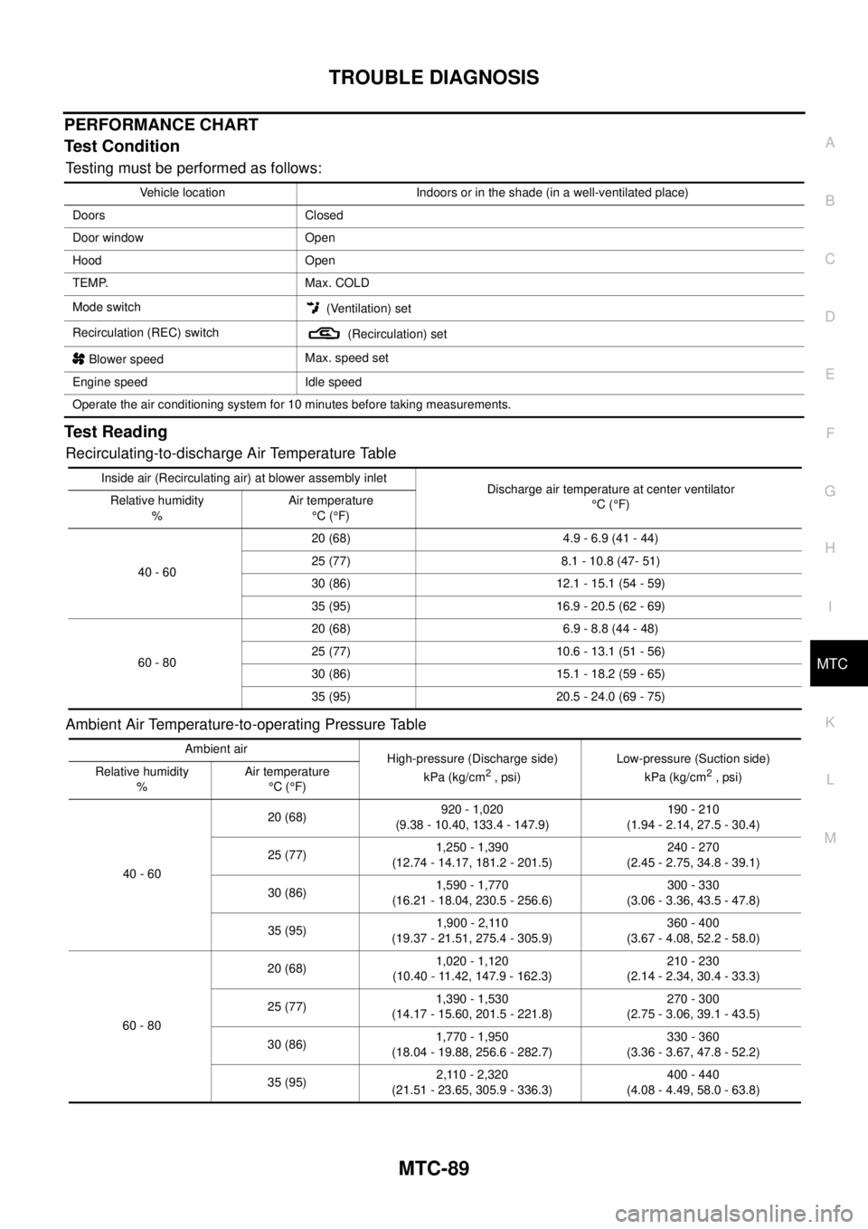
PERFORMANCE CHART
Test Condition
Testing must be performed as follows:
Test Reading
Recirculating-to-discharge Air Temperature Table
Ambient Air Temperature-to-operating Pressure Table
Vehicle location Indoors or in the shade (in a well-ventilated place)
Doors Closed
Door window Open
Hood Open
TEMP. Max. COLD
Mode switch
(Ventilation) set
Recirculation (REC) switch
(Recirculation) set
Blower speedMax. speed set
Engine speed Idle speed
Operate the air conditioning system for 10 minutes before taking measurements.
Inside air (Recirculating air) at blower assembly inlet
Discharge air temperature at center ventilator
°C(°F) Relative humidity
%Air temperature
°C(°F)
40 - 6020 (68) 4.9 - 6.9 (41 - 44)
25 (77) 8.1 - 10.8 (47- 51)
30 (86) 12.1 - 15.1 (54 - 59)
35 (95) 16.9 - 20.5 (62 - 69)
60 - 8020 (68) 6.9 - 8.8 (44 - 48)
25 (77) 10.6 - 13.1 (51 - 56)
30 (86) 15.1 - 18.2 (59 - 65)
35 (95) 20.5 - 24.0 (69 - 75)
Ambient air
High-pressure (Discharge side)
kPa (kg/cm
2,psi)Low-pressure (Suction side)
kPa (kg/cm2, psi) Relative humidity
%Air temperature
°C(°F)
40 - 6020 (68)920 - 1,020
(9.38 - 10.40, 133.4 - 147.9)190 - 210
(1.94 - 2.14, 27.5 - 30.4)
25 (77)1,250 - 1,390
(12.74 - 14.17, 181.2 - 201.5)240 - 270
(2.45 - 2.75, 34.8 - 39.1)
30 (86)1,590 - 1,770
(16.21 - 18.04, 230.5 - 256.6)300 - 330
(3.06 - 3.36, 43.5 - 47.8)
35 (95)1,900 - 2,110
(19.37 - 21.51, 275.4 - 305.9)360 - 400
(3.67 - 4.08, 52.2 - 58.0)
60 - 8020 (68)1,020 - 1,120
(10.40 - 11.42, 147.9 - 162.3)210 - 230
(2.14 - 2.34, 30.4 - 33.3)
25 (77)1,390 - 1,530
(14.17 - 15.60, 201.5 - 221.8)270 - 300
(2.75 - 3.06, 39.1 - 43.5)
30 (86)1,770 - 1,950
(18.04 - 19.88, 256.6 - 282.7)330 - 360
(3.36 - 3.67, 47.8 - 52.2)
35 (95)2,110 - 2,320
(21.51 - 23.65, 305.9 - 336.3)400 - 440
(4.08 - 4.49, 58.0 - 63.8)
Page 2547 of 3171

PG-18
IPDM E/R (INTELLIGENT POWER DISTRIBUTION MODULE ENGINE ROOM)
5. Touch “RECORD” while monitoring to record the status of the item being monitored. To stop recording,
touch “STOP”.
All Signals, Main Signals, Selection From Menu
NOTE:
Perform monitoring of IPDM E/R data with the ignition switch ON. When the ignition switch is in ACC position,
display may not be correct.
CAN DIAG SUPPORT MNTR
Refer toLAN-15, "CAN Diagnostic Support Monitor".
ACTIVE TEST
Operation Procedure
1. Touch “ACTIVE TEST” on “SELECT DIAG-MODE” screen.
2. Touch item to be tested, and check operation.
3. Touch “START”.
4. Touch “STOP” while testing to stop the operation.
Item nameCONSULT-II
screen displayDisplay or unitMonitor item selection
Description
ALL
SIGNALSMAIN
SIGNALSSELECTION
FROM MENU
Motor fan requestMOTOR FAN
REQ1/2/3/4 X X X Signal status input from ECM
A/C compressor
requestAC COMP REQ ON/OFF X X X Signal status input from ECM
Tail & clear
requestTAIL & CLR REQ ON/OFF X X X Signal status input from BCM
Headlamp LO
requestHL LO REQ ON/OFF X X X Signal status input from BCM
Headlamp HI
requestHL HI REQ ON/OFF X X X Signal status input from BCM
Front fog lamp
requestFR FOG REQ ON/OFF X X X Signal status input from BCM
Headlamp washer
requestHL WASHER
REQON/OFF X X Signal from input from BCM
Front wiper
requestFR WIP REQSTOP/1LOW/
LOW/HIX X X Signal status input from BCM
Wiper auto stopWIP AUTO
STOPACT P/STOP P X X X Output status of IPDM E/R
Wiper protection WIP PROT OFF/BLOCK X X X Control status of IPDM E/R
Starter request ST RLY REQ ON/OFF X X
Status of input signal
NOTE
Ignition relay
statusIGN RLY ON/OFF X X XIgnition relay status monitored
with IPDM E/R
Rear defogger
requestRR DEF REQ ON/OFF X X X Signal status input from BCM
Oil pressure
switchOIL P SW OPEN/CLOSE X XSignal status input from IPDM
E/R
Hood switch HOOD SW OFF XSignal status input from IPDM
E/R (function is not enabled)
Theft warning
horn requestTHFT HRN REQ ON/OFF X X Signal status input from BCM
Horn chirp HORN CHIRP ON/OFF X X Output status of IPDM E/R
Page 2548 of 3171
IPDM E/R (INTELLIGENT POWER DISTRIBUTION MODULE ENGINE ROOM)
PG-19
C
D
E
F
G
H
I
J
L
MA
B
PG
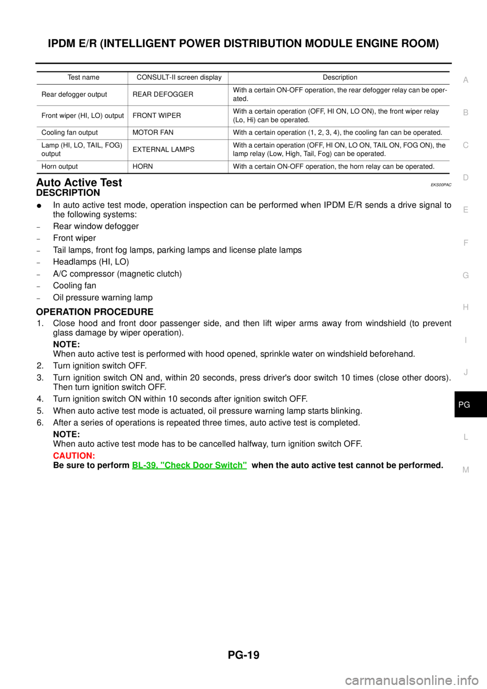
Auto Active TestEKS00PAC
DESCRIPTION
lIn auto active test mode, operation inspection can be performed when IPDM E/R sends a drive signal to
the following systems:
–Rear window defogger
–Front wiper
–Tail lamps, front fog lamps, parking lamps and license plate lamps
–Headlamps (HI, LO)
–A/C compressor (magnetic clutch)
–Cooling fan
–Oil pressure warning lamp
OPERATION PROCEDURE
1. Close hood and front door passenger side, and then lift wiper arms away from windshield (to prevent
glass damage by wiper operation).
NOTE:
When auto active test is performed with hood opened, sprinkle water on windshield beforehand.
2. Turn ignition switch OFF.
3. Turn ignition switch ON and, within 20 seconds, press driver's door switch 10 times (close other doors).
Then turn ignition switch OFF.
4. Turn ignition switch ON within 10 seconds after ignition switch OFF.
5. When auto active test mode is actuated, oil pressure warning lamp starts blinking.
6. After a series of operations is repeated three times, auto active test is completed.
NOTE:
When auto active test mode has to be cancelled halfway, turn ignition switch OFF.
CAUTION:
Be sure to performBL-39, "
Check Door Switch"when the auto active test cannot be performed.
Test name CONSULT-II screen display Description
Rear defogger output REAR DEFOGGERWith a certain ON-OFF operation, the rear defogger relay can be oper-
ated.
Front wiper (HI, LO) output FRONT WIPERWith a certain operation (OFF, HI ON, LO ON), the front wiper relay
(Lo, Hi) can be operated.
Cooling fan output MOTOR FAN With a certain operation (1, 2, 3, 4), the cooling fan can be operated.
Lamp (HI, LO, TAIL, FOG)
outputEXTERNAL LAMPSWith a certain operation (OFF, HI ON, LO ON, TAIL ON, FOG ON), the
lamp relay (Low, High, Tail, Fog) can be operated.
Horn output HORN With a certain ON-OFF operation, the horn relay can be operated.
Page 2678 of 3171

RF-1
ROOF
IBODY
CONTENTS
C
D
E
F
G
H
J
K
L
M
SECTIONRF
A
B
RF
ROOF
PRECAUTIONS .......................................................... 2
Precautions for Supplemental Restraint System
(SRS)“AIRBAG”and“SEATBELTPRE-TEN-
SIONER” .................................................................. 2
Precautions .............................................................. 2
PREPARATION ........................................................... 3
Commercial Service Tool ......................................... 3
SQUEAK AND RATTLE TROUBLE DIAGNOSES..... 4
Work Flow ................................................................ 4
CUSTOMER INTERVIEW ..................................... 4
DUPLICATE THE NOISE AND TEST DRIVE ....... 5
CHECK RELATED SERVICE BULLETINS ........... 5
LOCATE THE NOISE AND IDENTIFY THE
ROOT CAUSE ...................................................... 5
REPAIR THE CAUSE ........................................... 5
CONFIRM THE REPAIR ....................................... 6
Generic Squeak and Rattle Troubleshooting ........... 6
INSTRUMENT PANEL .......................................... 6
CENTER CONSOLE ............................................. 6
DOORS ................................................................. 6
TRUNK .................................................................. 7
SUNROOF/HEADLINING ..................................... 7
SEATS ................................................................... 7
UNDERHOOD ....................................................... 7
Diagnostic Worksheet .............................................. 8
SUNROOF ................................................................ 10
Component Parts and Harness Connector Location... 10
System Description ................................................. 11
TILT UP / SLIDE CLOSE OPERATION ................ 11
TILT DOWN / SLIDE OPEN OPERATION ........... 11AUTO OPERATION ............................................. 11
ANTI-PINCH FUNCTION .................................... 11
MEMORY RESET PROCEDURE ....................... 12
INITIALIZATION PROCEDURE .......................... 12
CAN Communication System Description .............. 13
CAN Communication Unit ....................................... 13
Wiring Diagram — SROOF — ................................ 14
Terminals and Reference Value for BCM ............... 15
Terminals and Reference Value for Sunroof Motor
Assembly ................................................................ 15
Work Flow ............................................................... 16
Trouble Diagnosis Symptom Chart ......................... 16
BCM Power Supply and Ground Circuit Check ...... 16
Sunroof Motor Assembly Power Supply and Ground
Circuit Check .......................................................... 17
Sunroof Switch System Check ............................... 18
Fitting Adjustment ................................................... 20
GAP ADJUSTMENT ............................................ 20
HEIGHT DIFFERENCE ADJUSTMENT .............. 20
Removal and Installation ........................................ 21
SUNROOF UNIT ................................................. 22
GLASS LID .......................................................... 22
WIND DEFLECTOR ............................................ 23
SUNSHADE ........................................................ 23
SUNROOF MOTOR ............................................ 23
DRAIN HOSES .................................................... 25
WEATHERSTRIP ................................................ 25
REAR DRAIN ASSEMBLY .................................. 25
LINK AND WIRE ASSEMBLY ............................. 26