alternator NISSAN NAVARA 2005 Repair Owner's Guide
[x] Cancel search | Manufacturer: NISSAN, Model Year: 2005, Model line: NAVARA, Model: NISSAN NAVARA 2005Pages: 3171, PDF Size: 49.59 MB
Page 2853 of 3171

SC-20
CHARGING SYSTEM
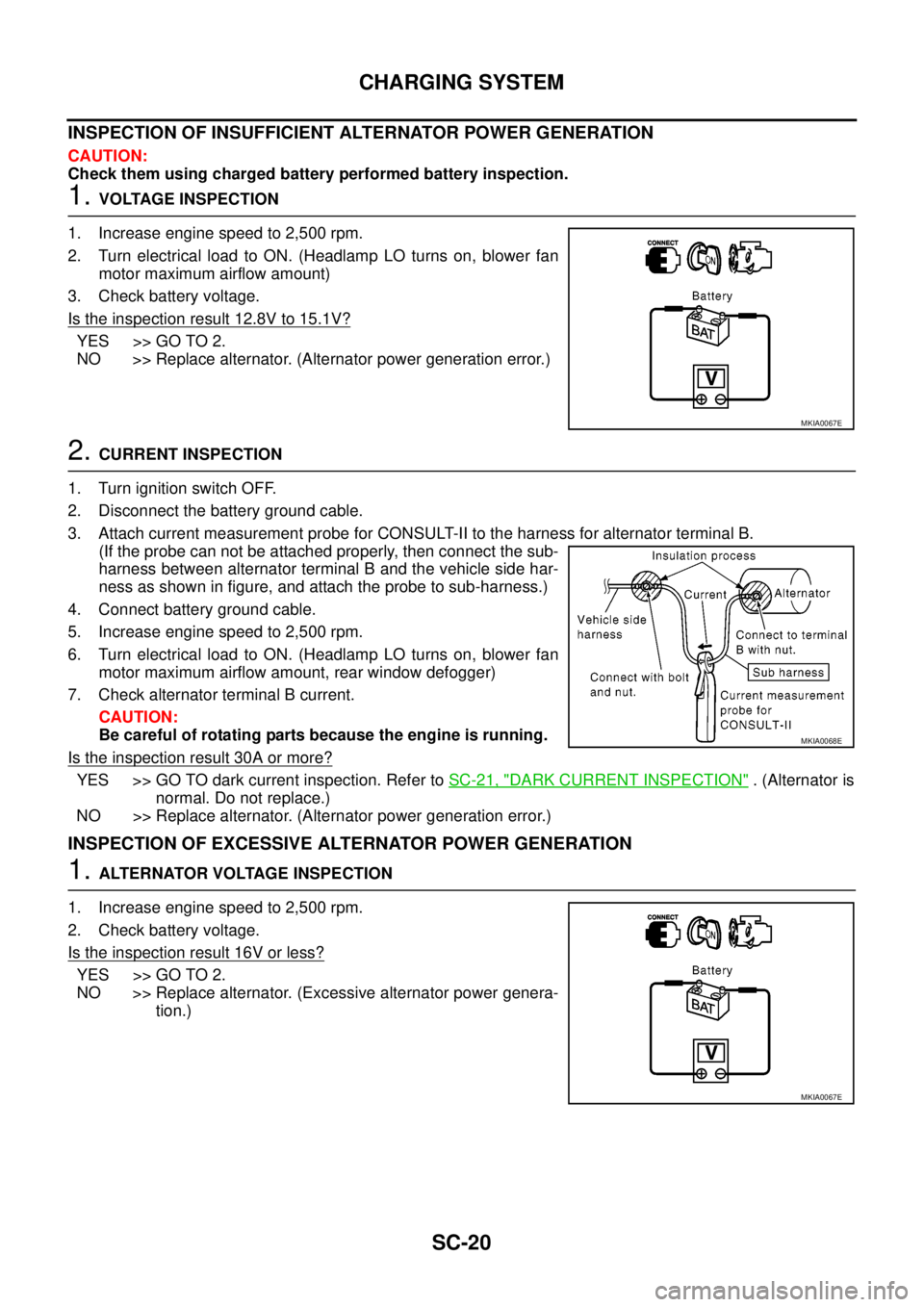
INSPECTION OF INSUFFICIENT ALTERNATOR POWER GENERATION
CAUTION:
Check them using charged battery performed battery inspection.
1.VOLTAGE INSPECTION
1. Increase engine speed to 2,500 rpm.
2. Turn electrical load to ON. (Headlamp LO turns on, blower fan
motor maximum airflow amount)
3. Check battery voltage.
Is the inspection result 12.8V to 15.1V?
YES >> GO TO 2.
NO >> Replace alternator. (Alternator power generation error.)
2.CURRENT INSPECTION
1. Turn ignition switch OFF.
2. Disconnect the battery ground cable.
3. Attach current measurement probe for CONSULT-II to the harness for alternator terminal B.
(If the probe can not be attached properly, then connect the sub-
harness between alternator terminal B and the vehicle side har-
ness as shown in figure, and attach the probe to sub-harness.)
4. Connect battery ground cable.
5. Increase engine speed to 2,500 rpm.
6. Turn electrical load to ON. (Headlamp LO turns on, blower fan
motor maximum airflow amount, rear window defogger)
7. Check alternator terminal B current.
CAUTION:
Be careful of rotating parts because the engine is running.
Is the inspection result 30A or more?
YES >> GO TO dark current inspection. Refer toSC-21, "DARK CURRENT INSPECTION". (Alternator is
normal. Do not replace.)
NO >> Replace alternator. (Alternator power generation error.)
INSPECTION OF EXCESSIVE ALTERNATOR POWER GENERATION
1.ALTERNATOR VOLTAGE INSPECTION
1. Increase engine speed to 2,500 rpm.
2. Check battery voltage.
Is the inspection result 16V or less?
YES >> GO TO 2.
NO >> Replace alternator. (Excessive alternator power genera-
tion.)
MKIA0067E
MKIA0068E
MKIA0067E
Page 2854 of 3171

CHARGING SYSTEM
SC-21
C
D
E
F
G
H
I
J
L
MA
B
SC
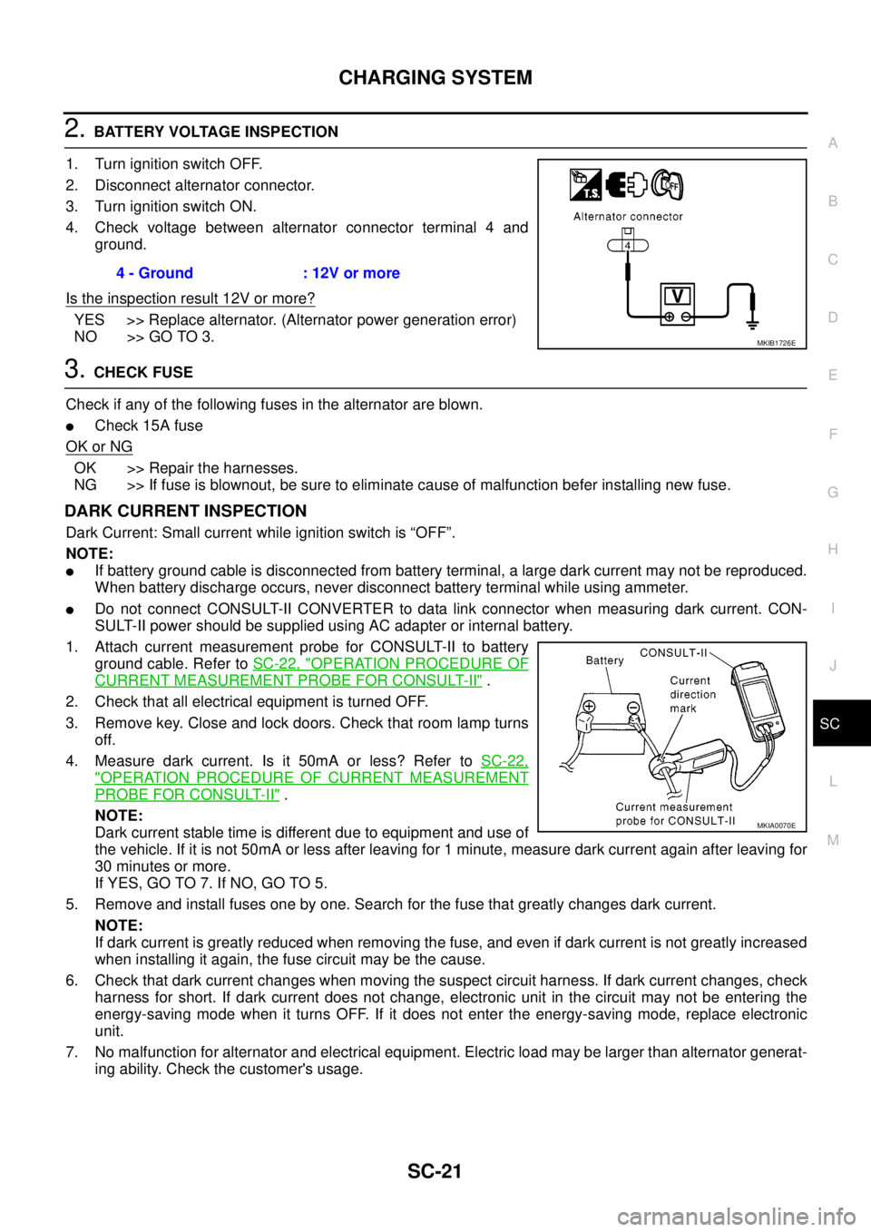
2.BATTERY VOLTAGE INSPECTION
1. Turn ignition switch OFF.
2. Disconnect alternator connector.
3. Turn ignition switch ON.
4. Check voltage between alternator connector terminal 4 and
ground.
Is the inspection result 12V or more?
YES >> Replace alternator. (Alternator power generation error)
NO >> GO TO 3.
3.CHECK FUSE
Check if any of the following fuses in the alternator are blown.
lCheck 15A fuse
OK or NG
OK >> Repair the harnesses.
NG >> If fuse is blownout, be sure to eliminate cause of malfunction befer installing new fuse.
DARK CURRENT INSPECTION
Dark Current: Small current while ignition switch is “OFF”.
NOTE:
lIf battery ground cable is disconnected from battery terminal, a large dark current may not be reproduced.
When battery discharge occurs, never disconnect battery terminal while using ammeter.
lDo not connect CONSULT-II CONVERTER to data link connector when measuring dark current. CON-
SULT-II power should be supplied using AC adapter or internal battery.
1. Attach current measurement probe for CONSULT-II to battery
ground cable. Refer toSC-22, "
OPERATION PROCEDURE OF
CURRENT MEASUREMENT PROBE FOR CONSULT-II".
2. Check that all electrical equipment is turned OFF.
3. Remove key. Close and lock doors. Check that room lamp turns
off.
4. Measure dark current. Is it 50mA or less? Refer toSC-22,
"OPERATION PROCEDURE OF CURRENT MEASUREMENT
PROBE FOR CONSULT-II".
NOTE:
Dark current stable time is different due to equipment and use of
the vehicle. If it is not 50mA or less after leaving for 1 minute, measure dark current again after leaving for
30 minutes or more.
If YES, GO TO 7. If NO, GO TO 5.
5. Remove and install fuses one by one. Search for the fuse that greatly changes dark current.
NOTE:
If dark current is greatly reduced when removing the fuse, and even if dark current is not greatly increased
when installing it again, the fuse circuit may be the cause.
6. Check that dark current changes when moving the suspect circuit harness. If dark current changes, check
harness for short. If dark current does not change, electronic unit in the circuit may not be entering the
energy-saving mode when it turns OFF. If it does not enter the energy-saving mode, replace electronic
unit.
7. No malfunction for alternator and electrical equipment. Electric load may be larger than alternator generat-
ing ability. Check the customer's usage.4 - Ground : 12V or more
MKIB1726E
MKIA0070E
Page 2856 of 3171

CHARGING SYSTEM
SC-23
C
D
E
F
G
H
I
J
L
MA
B
SC
Removal and InstallationEKS00MZE
REMOVAL
1. Disconnect negative battery cable.
2. Remove intercooler hose and duct
3. Disconnect alternator harness.
4. Remove drive belt. Refer toEM-12, "
Checking Drive Belts".
5. Remove alternator upper mounting bolt.
6. Remove alternator lower mounting nut and bolt .
7. Remove alternator.
INSTALLATION
Install in the reverse order of removal, taking care of the following point.
lInstall alternator, and check tension of drive belt. Refer toEM-13, "Deflection Adjustment".
CAUTION:
Be sure to tighten alternator terminal 1 mounting nut carefully.
Disassembly and AssemblyEKS00PD1
LHD MODELS
MKIB1992E
YD engine models - B terminal nut:
: 7.9 - 11.0 N·m (0.8 - 1.11 kg-m, 70 - 97 in-lb)
1. Rear bearing 2. Rotor 3. Retainer
4. Front bearing 5. Through bolt 6. Front cover
7. Washer 8. Pulley 9. Stator
10. IC voltage regulator assembly 11. Diode assembly 12. Rear cover
13. B terminal
MKIB2000E
Page 2858 of 3171

CHARGING SYSTEM
SC-25
C
D
E
F
G
H
I
J
L
MA
B
SC
InspectionEKS00MZH
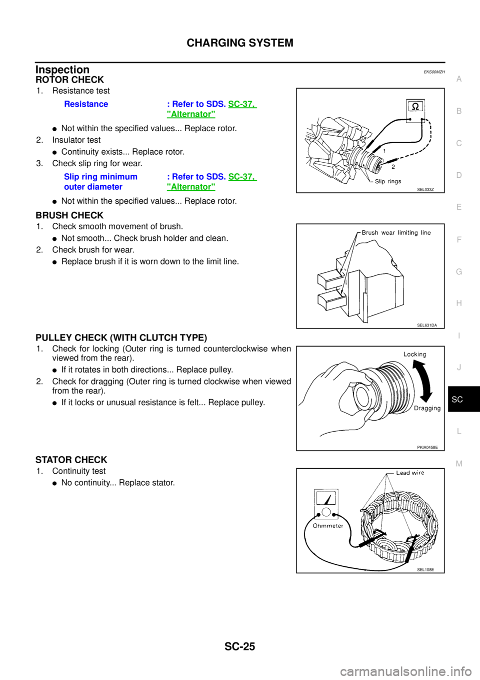
ROTOR CHECK
1. Resistance test
lNot within the specified values... Replace rotor.
2. Insulator test
lContinuity exists... Replace rotor.
3. Check slip ring for wear.
lNot within the specified values... Replace rotor.
BRUSH CHECK
1. Check smooth movement of brush.
lNot smooth... Check brush holder and clean.
2. Check brush for wear.
lReplace brush if it is worn down to the limit line.
PULLEY CHECK (WITH CLUTCH TYPE)
1. Check for locking (Outer ring is turned counterclockwise when
viewed from the rear).
lIf it rotates in both directions... Replace pulley.
2. Check for dragging (Outer ring is turned clockwise when viewed
from the rear).
lIf it locks or unusual resistance is felt... Replace pulley.
STATOR CHECK
1. Continuity test
lNo continuity... Replace stator.Resistance : Refer to SDS.SC-37,
"Alternator"
Slip ring minimum
outer diameter: Refer to SDS.SC-37,
"Alternator"SEL033Z
SEL631DA
PKIA0458E
SEL108E
Page 2870 of 3171

SERVICE DATA AND SPECIFICATIONS (SDS)
SC-37
C
D
E
F
G
H
I
J
L
MA
B
SC
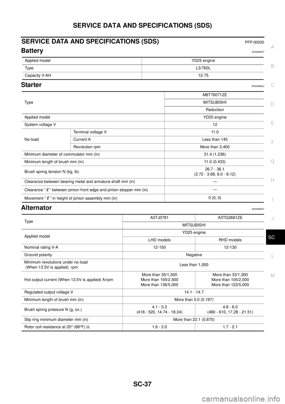
SERVICE DATA AND SPECIFICATIONS (SDS)PFP:00030
BatteryEKS00MZT
StarterEKS00MZU
AlternatorEKS00MZV
Applied modelYD25 engine
TypeL3/760L
Capacity V-AH12-75
Ty p eM8T76071ZE
MITSUBISHI
Reduction
Applied modelYD25 engine
System voltage V12
No-loadTerminal voltage V 11.0
Current A Less than 145
Revolution rpm More than 3,400
Minimum diameter of commutator mm (in) 31.4 (1.236)
Minimum length of brush mm (in) 11.0 (0.433)
Brush spring tension N (kg, lb)26.7 - 36.1
(2.72 - 3.68, 6.0 - 8.12)
Clearance between bearing metal and armature shaft mm (in) —
Clearance “ ” between pinion front edge and pinion stopper mm (in)—
Movement “ ” in height of pinion assembly mm (in)0 (0, 0)
TypeA3TJ0781 A3TG2681ZE
MITSUBISHI
Applied modelYD25 engine
LHD models RHD models
Nominal rating V-A 12-150 12-130
Ground polarityNegative
Minimum revolutions under no-load
(When 13.5V is applied) rpmLess than 1,000
Hot output current (When 13.5V is applied) A/rpmMore than 35/1,300
More than 105/2,500
More than 136/5,000More than 33/1,300
More than 105/2,500
More than 122/5,000
Regulated output voltage V 14.1 - 14.7
Minimum length of brush mm (in) More than 5.0 (0.197)
Brush spring pressure N (g, oz.)4.1 - 5.3
(418 - 520, 14.74 - 18.34)4.8 - 6.0
(490 - 610, 17.28 - 21.51)
Slip ring minimum diameter mm (in) More than 22.1 (0.870)
Rotor coil resistance at 20°(68°F)W1.6 - 2.0 1.7 - 2.1