Abs 4wd NISSAN NAVARA 2005 Repair Workshop Manual
[x] Cancel search | Manufacturer: NISSAN, Model Year: 2005, Model line: NAVARA, Model: NISSAN NAVARA 2005Pages: 3171, PDF Size: 49.59 MB
Page 914 of 3171
DI-4
COMBINATION METERS
COMBINATION METERS
PFP:24814
System DescriptionEKS00L8E
UNIFIED METER CONTROL UNIT
lSpeedometer, odo/trip meter, tachometer, fuel gauge and water temperature gauge are controlled by the
unified meter control unit, which is built into the combination meter.
lWarning lamp and indicator lamp are controlled by signals drawn from each unit with CAN communication
and components connected directly to the combination meter.
lOdo/trip meter display is included in the combination meter, which displays odometer, trip-meter, vehicle
information (trip computer, engine oil maintenance information)
*and A/T position*.
*: Vehicles with each system only.
lClock display is included in the combination meter, which displays current time, ambient air temperature*
and 4WD indicator*.
*: Vehicles with each system only.
lUnified meter control unit corresponds a CONSULT-II function (self-diagnosis results and data monitor).
lThe following items can be checked during self-diagnosis mode.
–Sweep of gauges pointer
–Present gauge values
–Odo/trip meter display and clock display segments
–Condition of warning lamps/indicator lamps controlled by unified meter control unit
–Battery voltage
–Driver's seat belt buckle switch status
–CPU status of unified meter control unit
POWER SUPPLY AND GROUND CIRCUIT
Power is supplied at all times
lthrough 10A fuse [No.19, located in the fuse block (J/B)]
lto combination meter terminal 3.
With the ignition switch in the ON or START position, power is supplied
lthrough 10A fuse [No.14, located in the fuse block (J/B)]
lto combination meter terminal 16.
Ground is supplied
lto combination meter terminals 13 and 23
lthrough grounds M21, M80 and M83.
SPEEDOMETER
The speedometer indicates the vehicle speed.
lABS actuator and electric unit (control unit) converses a pulse signal from wheel sensor to vehicle speed
signal, and transmits vehicle speed signal to combination meter with CAN communication.
lCombination meter converses the vehicle speed signal to angle signal, and commands to speedometer.
TACHOMETER
The tachometer indicates engine speed in revolutions per minute (rpm).
lECM converses a signal from crank position sensor to engine speed signal, and transmits to combination
meter with CAN communication.
lCombination meter converses the engine speed signal to angle signal, and commands to tachometer.
WATER TEMPERATURE GAUGE
The water temperature gauge indicates the engine coolant temperature.
lECM converses a signal from water temperature sensor to engine coolant temperature signal, and trans-
mits to combination meter with CAN communication.
lCombination meter converses the engine coolant temperature signal to angle signal, and commands to
water temperature gauge.
Page 1538 of 3171
FAX-6
WHEEL HUB
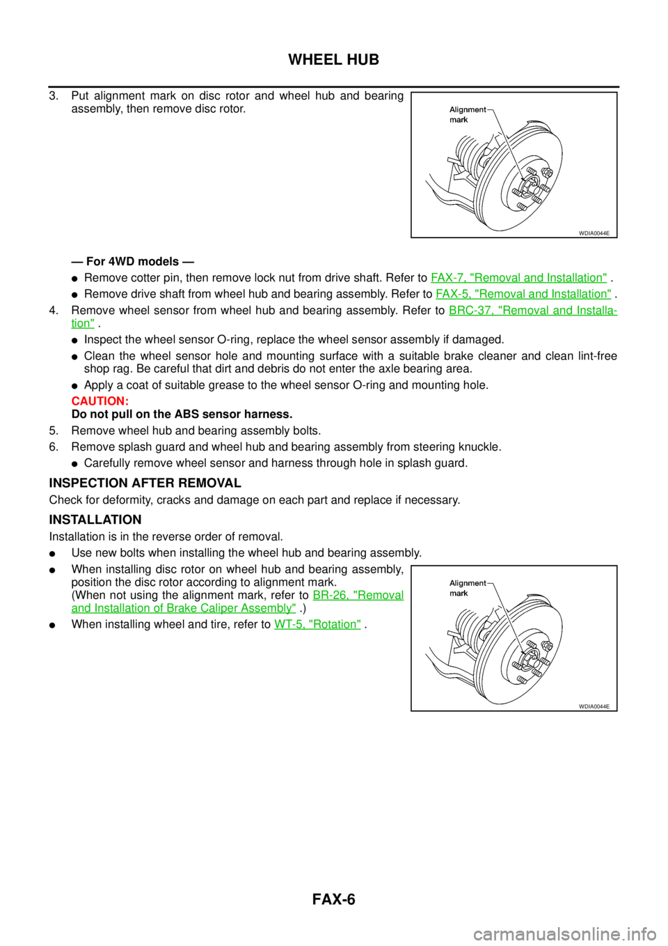
3. Put alignment mark on disc rotor and wheel hub and bearing
assembly, then remove disc rotor.
— For 4WD models —
lRemove cotter pin, then remove lock nut from drive shaft. Refer toFA X - 7 , "Removal and Installation".
lRemove drive shaft from wheel hub and bearing assembly. Refer toFAX-5, "Removal and Installation".
4. Remove wheel sensor from wheel hub and bearing assembly. Refer toBRC-37, "
Removal and Installa-
tion".
lInspect the wheel sensor O-ring, replace the wheel sensor assembly if damaged.
lClean the wheel sensor hole and mounting surface with a suitable brake cleaner and clean lint-free
shop rag. Be careful that dirt and debris do not enter the axle bearing area.
lApply a coat of suitable grease to the wheel sensor O-ring and mounting hole.
CAUTION:
Do not pull on the ABS sensor harness.
5. Remove wheel hub and bearing assembly bolts.
6. Remove splash guard and wheel hub and bearing assembly from steering knuckle.
lCarefully remove wheel sensor and harness through hole in splash guard.
INSPECTION AFTER REMOVAL
Check for deformity, cracks and damage on each part and replace if necessary.
INSTALLATION
Installation is in the reverse order of removal.
lUse new bolts when installing the wheel hub and bearing assembly.
lWhen installing disc rotor on wheel hub and bearing assembly,
position the disc rotor according to alignment mark.
(When not using the alignment mark, refer toBR-26, "
Removal
and Installation of Brake Caliper Assembly".)
lWhen installing wheel and tire, refer toWT-5, "Rotation".
WDIA0044E
WDIA0044E
Page 1606 of 3171
FSU-6
FRONT SUSPENSION ASSEMBLY
FRONT SUSPENSION ASSEMBLY
PFP:54010
ComponentsEES002KL
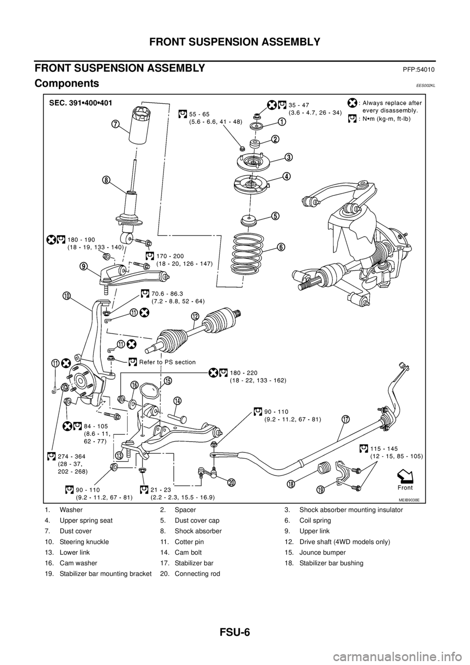
1. Washer 2. Spacer 3. Shock absorber mounting insulator
4. Upper spring seat 5. Dust cover cap 6. Coil spring
7. Dust cover 8. Shock absorber 9. Upper link
10. Steering knuckle 11. Cotter pin 12. Drive shaft (4WD models only)
13. Lower link 14. Cam bolt 15. Jounce bumper
16. Cam washer 17. Stabilizer bar 18. Stabilizer bar bushing
19. Stabilizer bar mounting bracket 20. Connecting rod
MEIB9038E
Page 1607 of 3171
ON-VEHICLE SERVICE
FSU-7
C
D
F
G
H
I
J
K
L
MA
B
FSU
ON-VEHICLE SERVICEPFP:00000
Front Suspension PartsEES002KM
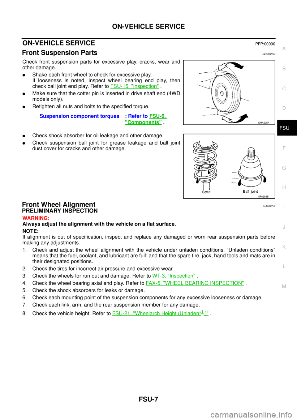
Check front suspension parts for excessive play, cracks, wear and
other damage.
lShake each front wheel to check for excessive play.
If looseness is noted, inspect wheel bearing end play, then
check ball joint end play. Refer toFSU-15, "
Inspection".
lMake sure that the cotter pin is inserted in drive shaft end (4WD
models only).
lRetighten all nuts and bolts to the specified torque.
lCheck shock absorber for oil leakage and other damage.
lCheck suspension ball joint for grease leakage and ball joint
dust cover for cracks and other damage.
Front Wheel AlignmentEES002KN
PRELIMINARY INSPECTION
WARNING:
Always adjust the alignment with the vehicle on a flat surface.
NOTE:
If alignment is out of specification, inspect and replace any damaged or worn rear suspension parts before
making any adjustments.
1. Check and adjust the wheel alignment with the vehicle under unladen conditions. “Unladen conditions”
means that the fuel, coolant, and lubricant are full; and that the spare tire, jack, hand tools and mats are in
their designated positions.
2. Check the tires for incorrect air pressure and excessive wear.
3. Check the wheels for run out and damage. Refer toWT-3, "
Inspection".
4. Check the wheel bearing axial end play. Refer toFA X - 5 , "
WHEEL BEARING INSPECTION".
5. Check the shock absorbers for leaks or damage.
6. Check each mounting point of the suspension components for any excessive looseness or damage.
7. Check each link, arm, and the rear suspension member for any damage.
8. Check the vehicle height. Refer toFSU-21, "
Wheelarch Height (Unladen*1)". Suspension component torques : Refer toFSU-6,
"Components".SMA525A
SFA392B
Page 1619 of 3171
SERVICE DATA AND SPECIFICATIONS (SDS)
FSU-19
C
D
F
G
H
I
J
K
L
MA
B
FSU
SERVICE DATA AND SPECIFICATIONS (SDS)PFP:00030
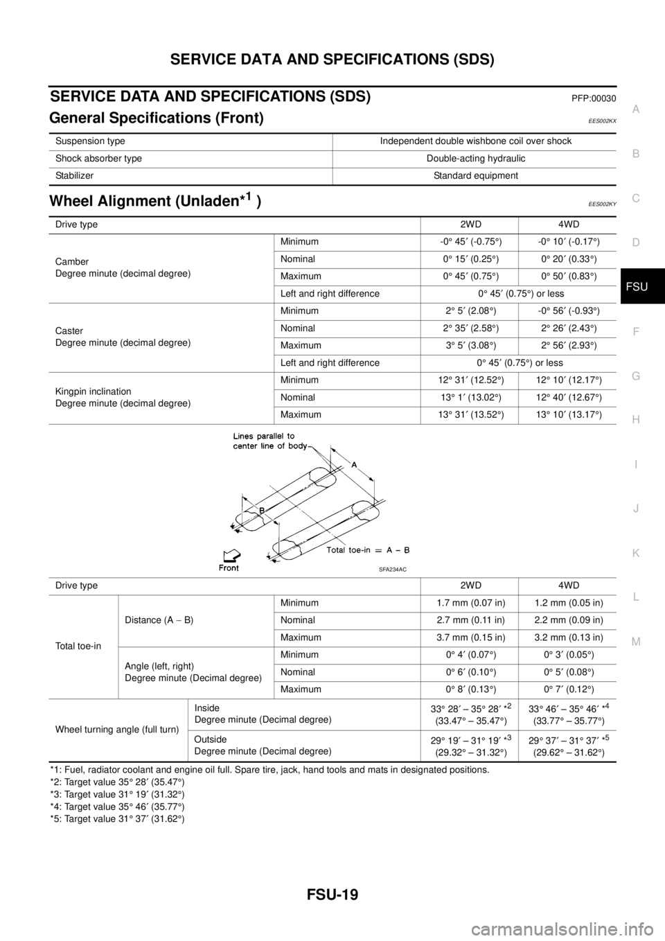
General Specifications (Front)EES002KX
Wheel Alignment (Unladen*1)EES002KY
*1: Fuel, radiator coolant and engine oil full. Spare tire, jack, hand tools and mats in designated positions.
*2: Target value 35°28¢(35.47°)
*3: Target value 31°19¢(31.32°)
*4: Target value 35°46¢(35.77°)
*5: Target value 31°37¢(31.62°) Suspension type Independent double wishbone coil over shock
Shock absorber type Double-acting hydraulic
StabilizerStandard equipment
Drive type2WD 4WD
Camber
Degree minute (decimal degree)Minimum -0°45¢(-0.75°)-0°10¢(-0.17°)
Nominal 0°15¢(0.25°)0°20¢(0.33°)
Maximum 0°45¢(0.75°)0°50¢(0.83°)
Left and right difference 0°45¢(0.75°)orless
Caster
Degree minute (decimal degree)Minimum 2°5¢(2.08°)-0°56¢(-0.93°)
Nominal 2°35¢(2.58°)2°26¢(2.43°)
Maximum 3°5¢(3.08°)2°56¢(2.93°)
Left and right difference 0°45¢(0.75°)orless
Kingpin inclination
Degree minute (decimal degree)Minimum 12°31¢(12.52°)12°10¢(12.17°)
Nominal 13°1¢(13.02°)12°40¢(12.67°)
Maximum 13°31¢(13.52°)13°10¢(13.17°)
Drive type2WD 4WD
Total toe-inDistance (A-B)Minimum 1.7 mm (0.07 in) 1.2 mm (0.05 in)
Nominal 2.7 mm (0.11 in) 2.2 mm (0.09 in)
Maximum 3.7 mm (0.15 in) 3.2 mm (0.13 in)
Angle (left, right)
Degree minute (Decimal degree)Minimum 0°4¢(0.07°)0°3¢(0.05°)
Nominal 0°6¢(0.10°)0°5¢(0.08°)
Maximum 0°8¢(0.13°)0°7¢(0.12°)
Wheel turning angle (full turn)Inside
Degree minute (Decimal degree)33°28¢–35°28¢*
2
(33.47°– 35.47°)33°46¢–35°46¢*
4
(33.77°– 35.77°)
Outside
Degree minute (Decimal degree)29°19¢–31°19¢*
3
(29.32°– 31.32°)29°37¢–31°37¢*
5
(29.62°– 31.62°)
SFA234AC
Page 1669 of 3171
CONSULT-II CHECKING SYSTEM
GI-47
C
D
E
F
G
H
I
J
K
L
MB
GI
CONSULT-II CHECKING SYSTEMPFP:00000
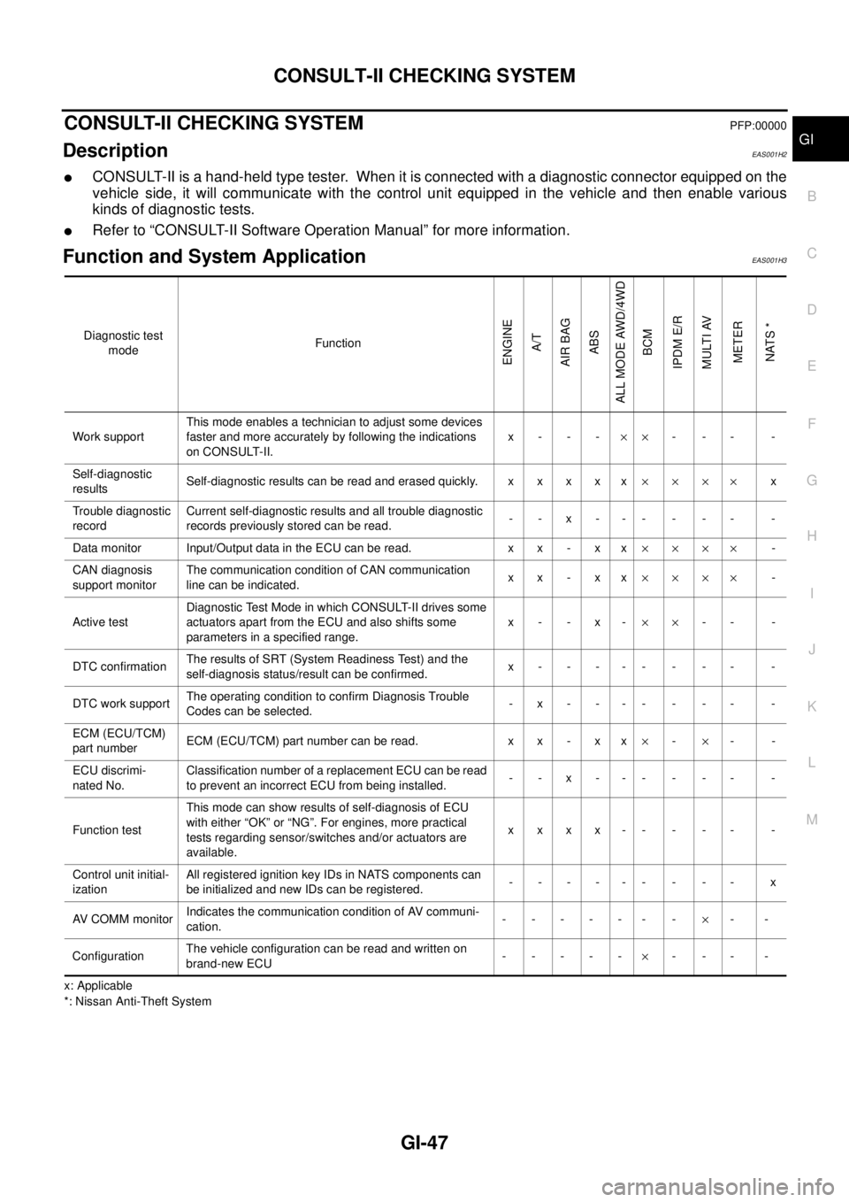
DescriptionEAS001H2
lCONSULT-II is a hand-held type tester. When it is connected with a diagnostic connector equipped on the
vehicle side, it will communicate with the control unit equipped in the vehicle and then enable various
kinds of diagnostic tests.
lRefer to “CONSULT-II Software Operation Manual” for more information.
Function and System ApplicationEAS001H3
x: Applicable
*: Nissan Anti-Theft SystemDiagnostic test
modeFunction
ENGINE
A/T
AIR BAG
ABS
ALL MODE AWD/4WD
BCM
IPDM E/R
MULTI AV
METER
NATS *
Work supportThis mode enables a technician to adjust some devices
faster and more accurately by following the indications
on CONSULT-II.x---´´--- -
Self-diagnostic
resultsSelf-diagnostic results can be read and erased quickly. x x x x x´´´´x
Trouble diagnostic
recordCurrent self-diagnostic results and all trouble diagnostic
records previously stored can be read.--x------ -
Data monitor Input/Output data in the ECU can be read. x x - x x´´´´-
CAN diagnosis
support monitorThe communication condition of CAN communication
line can be indicated.xx - xx´´´´-
Active testDiagnostic Test Mode in which CONSULT-II drives some
actuators apart from the ECU and also shifts some
parameters in a specified range.x- -x-´´-- -
DTC confirmationThe results of SRT (System Readiness Test) and the
self-diagnosis status/result can be confirmed.x----- - -- -
DTC work supportThe operating condition to confirm Diagnosis Trouble
Codes can be selected.-x------- -
ECM (ECU/TCM)
part numberECM (ECU/TCM) part number can be read. x x - x x´-´--
ECU discrimi-
nated No.Classification number of a replacement ECU can be read
to prevent an incorrect ECU from being installed.--x------ -
Function testThis mode can show results of self-diagnosis of ECU
with either “OK” or “NG”. For engines, more practical
tests regarding sensor/switches and/or actuators are
available.xxxx-- - - - -
Control unit initial-
izationAll registered ignition key IDs in NATS components can
be initialized and new IDs can be registered.------ - -- x
AV C O M M m o n i t o rIndicates the communication condition of AV communi-
cation.- ----- -´--
ConfigurationThe vehicle configuration can be read and written on
brand-new ECU- ----´--- -
Page 1754 of 3171
IDX-2
ALPHABETICAL INDEX
Numerics
4LO indicator lamp .............................................TF-16
4LO switch ..............................................TF-56,TF-59
4WD - Wiring diagram .......................................TF-25
4WD shift indicator lamp ....................................TF-16
4WD shift switch .........................TF-16,TF-59,TF-62
4WD system description ....................................TF-15
4WD system diagram ........................................TF-18
4WD warning lamp ............................................TF-17
A
A/C air flow .......................................ATC-30
,MTC-30
A/C compressor clutch removal and installation ...........
ATC-143
,MTC-123
A/C compressor mounting ............ATC-142,MTC-122
A/C compressor precaution ..............ATC-12,MTC-12
A/C compressor special service tool .ATC-16,MTC-16
A/C control operation (auto A/C) .......ATC-28,MTC-28
A/C diagnostic work flow (auto A/C)ATC-103,MTC-95
A/C evaporator ..............................ATC-149,MTC-129
A/C HFC134a (R134a) system precaution .......ATC-4,
MTC-4
A/C HFC134a (R134a) system service procedure .......
ATC-138
,MTC-118
A/C HFC134a (R134a) system service tools ..ATC-16,
MTC-16
A/C HFC134a system service equipment precaution ...
ATC-12
,MTC-12
A/C lubricant (R134a) .......................ATC-24,MTC-24
A/C lubrication oil ..............................ATC-24,MTC-24
A/C operational check .......................ATC-57,MTC-53
A/C self-diagnoses (auto A/C) .......ATC-55,ATC-103,
MTC-51
,MTC-95
A/C service data specification .......ATC-154,MTC-135
A/C trouble diagnoses (auto A/C) .....ATC-33,MTC-33
A/C, A - Wiring diagram ....................ATC-39,MTC-39
A/T fluid checking ......................AT-12,AT-43,MA-29
A/T fluid replacement .............................AT-11,MA-31
A/T fluid temperature sensor ...........................AT-118
A/T IND - Wiring diagram ....................................DI-49
A/T indicator ........................................................DI-48
A/T self-diagnoses .............................................AT-89
A/T shift lock system ........................................AT-212
A/T trouble diagnoses ........................................AT-34
A/T Wiring diagram AT - CAN ............................AT-92
A/T Wiring diagram AT - FTS ..........................AT-119
A/T Wiring diagram AT - MAIN ........................AT-164
A/T Wiring diagram AT - NONDTC ..................AT-174
A/T Wiring diagram AT - PNP/SW ...................AT-100
A/T Wiring diagram AT - STSIG ........................AT-95
A/T Wiring diagram AT - VSS A/T ...................AT-105
ABS - Wiring diagram .....................................BRC-13
Accelerator control system ...............................ACC-2
Accelerator pedal position (APP) sensor ........EC-108,
EC-142
,EC-275
Aiming adjustment ..................................LT-28,LT-85
Air bag ..............................................................SRS-3
Air bag disposal ..............................................SRS-49
Air bleeding (hydraulic clutch) ..............................CL-8
Air cleaner and air duct .....................................EM-15
Air cleaner filter .................................................EM-17
Air cleaner filter replacement ............................MA-25
Air conditioner cut control ..................................EC-20
Air flow meter - See Mass air flow sensor ..........EC-92
Air mix. door motor .........................................ATC-68
Alternator ...........................................................SC-14
Ambient sensor .............................ATC-105,ATC-117
Angular tightening application .............................EM-4
APP2PW - Wiring diagram ..............................EC-229
APPS - Wiring diagram ....................................EC-110
APPS2 - Wiring diagram ..................................EC-144
APPS3 - Wiring diagram ..................................EC-277
ASC/BS - Wiring diagram ................................EC-192
ASC/SW - Wiring diagram ...............................EC-208
ASCBOF - Wiring diagram ...............................EC-331
ASCD ...............................................................EC-355
ASCD (automatic speed control device) ...........ACS-2
ASCD brake switch ...........................EC-189,EC-330
ASCD clutch switch ..........................EC-189,EC-330
ASCD indicator lamp .......................................EC-351
ASCD steering switch ......................................EC-206
ASCIND - Wiring diagram ................................EC-352
ATP switch ..............................................TF-82,TF-85
Auto air conditioner - Wiring diagramATC-39,MTC-39
Auto anti-dazzling inside mirror .......................GW-45
Autolamp ............................................................LT-49
Automatic amplifier ..........................ATC-60,MTC-55
Automatic transmission number ..............GI-58,GI-59
B
Back door trim .....................................................EI-30
BACK/L - Wiring diagram .................................LT-123
Back-up lamp ...................................................LT-123
Back-up lamp switch (M/T) ...................MT-12,MT-19
Ball joint (front) ................................................FSU-15
Barometric pressure (BARO) sensor ...............EC-293
Basic inspection .................................................EC-38
Battery .................................................................SC-5
Baulk ring (M/T) ................................................MT-21
BCM (Body control module) ..............................BCS-3
Blower motor ...ATC-80,ATC-121,MTC-71,MTC-100
Body mounting ....................................BL-189,BL-190
BOOST - Wiring diagram .................................EC-155
Brake booster ....................................................BR-19
Brake fluid level ................................................MA-35
Brake inspection ...............................................MA-35
Brake lines and cables inspection ....................MA-35
Brake master cylinder ........................................BR-17
Brake pedal ..........................................................BR-6
Brake switch ....................................................EC-330
Bulb specifications ...........................................LT-173
Bumper, front ......................................................EI-15
Bumper, rear .......................................................EI-17
Page 1788 of 3171

TROUBLE DIAGNOSES WORK FLOW
LAN-11
[CAN]
C
D
E
F
G
H
I
J
L
MA
B
LAN
3. Confirm the unit name that “UNKWN” is displayed on the copy of “CAN DIAG SUPPORT MNTR” screen
of “A/T”, “HVAC”, “BCM”, “ABS” and “IPDM E/R” as well as “ENGINE”. And then, put a check mark to the
check sheet table.
NOTE:
lFor “A/T”, “UNKWN” is displayed on “METER/M&A”, “ICC/e4WD” and “AWD/4WD”. But put a check
mark to “METER/M&A” because “UNKWN” is listed on the column of reception diagnosis of the check
sheet table.
lFor “HVAC”, “UNKWN” is not displayed. Do not put a check mark to it.
lFor “BCM”, “UNKWN” is displayed on “METER/M&A” and “I-KEY”. But put a check mark to “METER/
M&A” because “UNKWN” is listed on the column of reception diagnosis of the check sheet table.
lFor “ABS”, “UNKWN” is not displayed. Do not put a check mark to it.
lFor “IPDM E/R”, “UNKWN” is not displayed. Do not put a check mark to it.
PKIC2527E
Page 1793 of 3171

LAN-16
[CAN]
TROUBLE DIAGNOSES WORK FLOW
DESCRIPTION OF “CAN DIAG SUPPORT MNTR” SCREEN
FOR TCM
Display Results (Present)
lOK: Normal
lNG: Malfunction
lUNKWN: The diagnosed unit does not transmit or receive the applicable data normally.
SKIB2335E
“SELECT SYSTEM”
screen“CAN DIAG SUPPORT
MNTR” screenDescription Present
A/TINITIAL DIAG Make sure that microcomputer in ECU works normally. OK/NG
TRANSMIT DIAG Make sure of normal transmission. OK/UNKWN
ECM Make sure of normal reception from ECM. OK/UNKWN
VDC/TCS/ABS VDC/TCS/ABS is not diagnosed. OK
METER/M&A Make sure of normal reception from combination meter. OK/UNKWN
ICC/e4WD ICC/e4WD is not diagnosed. UNKWN
AWD/4WD Make sure of normal reception from transfer control unit. OK/UNKWN
Page 1795 of 3171

LAN-18
[CAN]
TROUBLE DIAGNOSES WORK FLOW
DESCRIPTION OF “CAN DIAG SUPPORT MNTR” SCREEN
FOR DIFFERENTIAL LOCK CONTROL UNIT
Display Results (Present)
lOK: Normal
lNG: Malfunction
lUNKWN: The diagnosed unit does not transmit or receive the applicable data normally.
PKIB7196E
“SELECT SYSTEM”
screen“CAN DIAG SUPPORT
MNTR” screenDescription Present
DIFF LOCKINITIAL DIAG Make sure that microcomputer in ECU works normally. OK/NG
TRANSMIT DIAG Make sure of normal transmission. OK/UNKWN
ECM Make sure of normal reception from ECM. OK/UNKWN
VDC/TCS/ABSMake sure of normal reception from ABS actuator and electric unit
(control unit).OK/UNKWN
AWD/4WD Make sure of normal reception from transfer control unit. OK/UNKWN