engine NISSAN NOTE 2006 Owner's Manual
[x] Cancel search | Manufacturer: NISSAN, Model Year: 2006, Model line: NOTE, Model: NISSAN NOTE 2006Pages: 235, PDF Size: 2.29 MB
Page 62 of 235
5. When the vehicle’s interior has warmed-up, or
before you leave the vehicle, be sure to turn the
seat heater system off.
CAUTION
•Do not use the seat heater system for a long
period of time when the engine is not running,
otherwise the battery could run down.
•Do not put anything on the seat that insulates
the heat, such as a blanket, cushion, seat
cover, etc. Otherwise, the seat may overheat.
•Do not place anything hard or heavy on the
seat or pierce it with a pin or similar object.
This may damage the heater.
•Any liquid spilled on a heated seat should be
removed immediately with a dry cloth.
•When cleaning the seat, never use benzine,
thinner or any similar materials.
•If any abnormalities are found or the heating
does not operate, turn off the switch and have
the system checked by a NISSAN dealer or
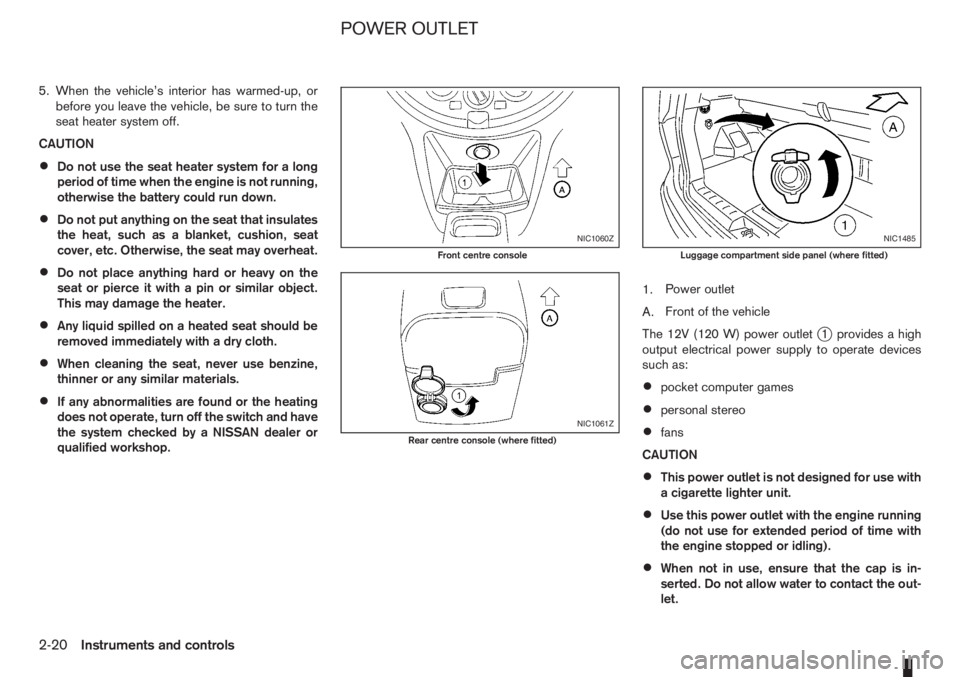
qualified workshop.1.Power outlet
A.Front of the vehicle
The 12V (120 W) power outlet
j1 provides a high
output electrical power supply to operate devices
such as:
•pocket computer games
•personal stereo
•fans
CAUTION
•This power outlet is not designed for use with
a cigarette lighter unit.
•Use this power outlet with the engine running
(do not use for extended period of time with
the engine stopped or idling).
•When not in use, ensure that the cap is in-
serted. Do not allow water to contact the out-
let.
NIC1060Z
Front centre console
NIC1061Z
Rear centre console (where fitted)
NIC1485
Luggage compartment side panel (where fitted)
POWER OUTLET
2-20Instruments and controls
Page 69 of 235
WARNING
There are some areas immediately before the
closed position where squeezing cannot be de-
tected. Be careful not to pinch your fingers.CAUTION
Do not use for extended periods of time with the
engine stopped. This could discharge the bat-
tery.
NOTE
The interior lights will go off after approximately
15 minutes unless the ignition switch is in the
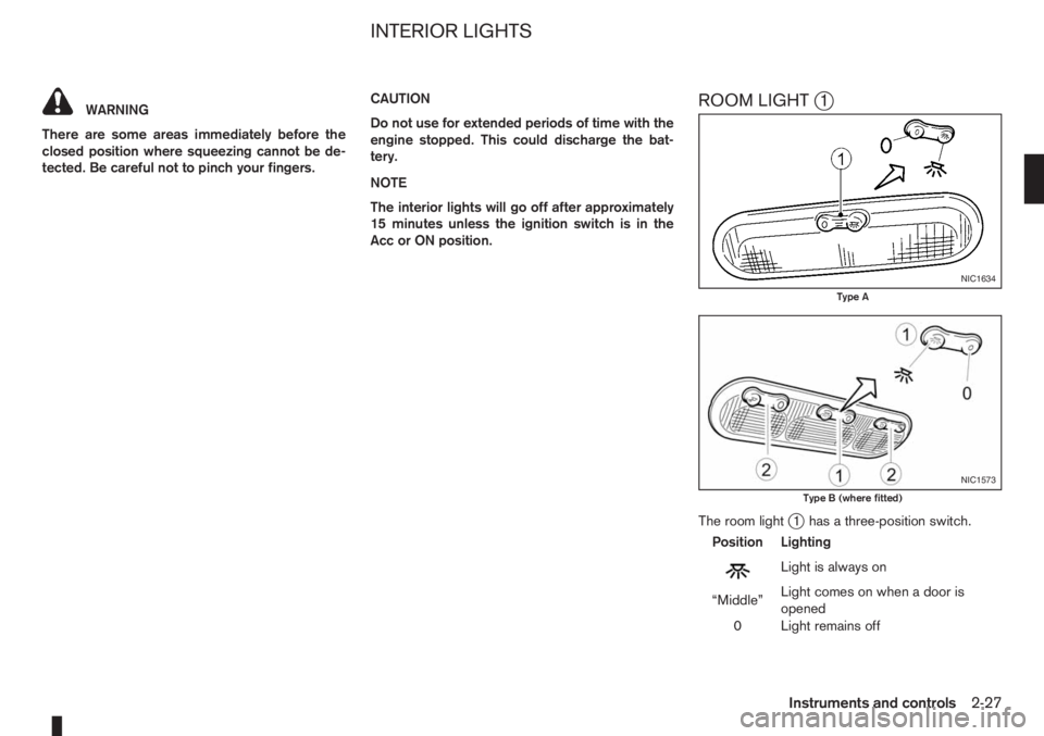
Acc or ON position.ROOM LIGHTj1
The room lightj1 has a three-position switch.
Position Lighting
mLightisalwayson
“Middle”Light comes on when a door is
opened
0 Light remains off
NIC1634
Type A
NIC1573
Type B (where fitted)
INTERIOR LIGHTS
Instruments and controls2-27
Page 71 of 235
3Pre-driving checks and adjustmentsPre-driving checks and adjustments
Keys ........................................................................ 3-2
Integrated keyfob/remote control system .................. 3-3
Using the remote keyless entry system ................ 3-3
Locking the doors ............................................... 3-3
Unlocking the doors – convenience mode ........... 3-4
Unlocking the doors – anti-hijack mode ............... 3-4
Switching from convenience mode to
anti-hijack mode.................................................. 3-4
Keyfob operation failure ...................................... 3-4
Intelligent Key system (where fitted) ......................... 3-5
Locking/unlocking .............................................. 3-5
Starting the engine with the Intelligent Key .......... 3-6
Door locks ............................................................... 3-6
Super Lock System (Right-hand drive models) .... 3-6
Vehicle dead battery – left-hand side door
handle ................................................................ 3-7
Locking with power door lock switch .................. 3-7Child safety rear door lock .................................. 3-8
Back door lock ................................................... 3-8
Security system ....................................................... 3-9
NISSAN Anti-Theft System (NATS)..................... 3-9
Bonnet release ........................................................ 3-10
Fuel filler lid ............................................................. 3-11
Fuel filler lid opener lever .................................... 3-11
Fuel filler cap ...................................................... 3-11
Handbrake lever ...................................................... 3-11
Tilting steering wheel ............................................... 3-12
Mirrors..................................................................... 3-12
Inside rear-view mirror ........................................ 3-12
Outside rear-view mirrors.................................... 3-12
Vanity mirror ....................................................... 3-13
Rear parcel shelf...................................................... 3-14
Rear parcel shelf removal.................................... 3-14
Rear parcel shelf installation................................ 3-14
Page 76 of 235
•The Intelligent Key contains a miniature radio
transmitter that may be affected when placed
near metal objects.
•Keep the Intelligent Key away from mobile
phones, lap-top computers and other metal
objects or electronics.
STARTING THE ENGINE WITH THE
INTELLIGENT KEY
See “Ignition knob (where fitted)” in the “5. Starting
and driving” section.
CAUTION
•Make sure you carry the Intelligent Key with
you when starting and driving the vehicle.
•If the Intelligent Key is too far away from the
passenger compartment, the vehicle may not
start.
WARNING
•Always look before opening any doors, to
avoid an accident with oncoming traffic.
•Never leave children or adults who would nor-
mally require the support of others alone in
the vehicle. They could unknowingly activate
switches or controls and inadvertently
become involved in a serious accident.
SUPER LOCK SYSTEM (Right-hand
drive models)
WARNING
For Super Lock System equipped models, failure
to follow the precautions below may lead to haz-
ardous situations. Make sure the Super Lock Sys-
tem activation is always safely conducted.
•When the vehicle is occupied, never lock the
doors with the integrated keyfob. Doing so
will trap the occupants, since the Super Lock
System prevents the doors from being opened
from the inside of the vehicle.
•Only operate the integrated keyfob lock but-
ton when there is a clear view of the vehicle.
This is to prevent anybody from being trapped
inside the vehicle through the Super Lock
System activation.
Locking the doors with the integrated keyfob will
lock all doors including the back door and activate
the Super Lock System. This means that none ofthe doors can be opened from the inside, adding
extra security in case of break-in or theft.
The system will be released when the door is un-
locked with the integrated keyfob.
The Super Lock System will not activate when the
doors are locked with the power door lock switch or
the key.
Emergency situations
If the Super Lock System is activated due to a traf-
fic accident or other unexpected circumstances
while you are in the vehicle:
•Insert the key/emergency key in the ignition
switch, turn it to the ON position, the Super Lock
system will be released and all doors can be
unlocked.
•Open or break the door window on the front
passenger’s side, remove the protection cap on
the passenger’s side door handle, insert the key
into the passenger’s side door key cylinder and
turn it to the unlock position, after which you will
be able to open the door.
•Remove the key from the ignition switch and un-
lock the door using the integrated keyfob.
DOOR LOCKS
3-6Pre-driving checks and adjustments
Page 79 of 235
WARNING
•Do not drive with the back door opened. This
could allow dangerous exhaust gases to be
drawn into the vehicle.
•Closely supervise children when they are
around the vehicle to prevent them from play-
ing and being locked in the luggage compart-
ment where they could be seriously injured.
Keep the vehicle locked, with the back door
closed, when not in use, and prevent chil-
dren’s access to the vehicle’s keys.
NISSAN ANTI-THEFT SYSTEM (NATS)
The NISSAN Anti-Theft System (NATS)* will not
allow the engine to start without the use of the reg-
istered NATS key.
* Immobilizer
If the engine fails to start using the registered NATS
key, it may be due to interference from another
NATS key, an automated toll road device or an auto-
mated payment device on the key ring. Restart the
engine using the following procedure:
1. Leave the ignition switch in the ON position for
approximately 5 seconds.
2. Turn the ignition switch to the “OFF” or LOCK
position and wait approximately 5 seconds.
3. Repeat steps 1 and 2.
4. Restart the engine while holding the device
(which may have caused the interference) sepa-
rated from the registered NATS key or NATS
Intelligent Key (where fitted).
If this procedure allows the engine to start,
NISSAN recommends placing the registered
NATS key or NATS Intelligent Key (where fitted)
on a separate key-ring to avoid interference from
other devices.
NATS security warning light
The security warning light blinks whenever the igni-
tion switch is in the LOCK, “OFF” or Acc position.
This function indicates that NATS is equipped on
the vehicle.
If the NISSAN Anti-Theft System (NATS) is mal-
functioning, this light will remain on while the ignition
key is in the ON position.
If the light remains on and/or the engine will not
start, see your NISSAN dealer for NATS service
as soon as possible. Please bring all NATS keys
or NATS Intelligent Keys when visiting your
NISSAN dealer for service.
Additional information for RHD models
If the NATS is malfunctioning, this light will turn on
after flashing six times while the ignition switch is in
the ON position.
However, if the NATS security warning light turns
off after the light has remained on for 15 minutes,
SIC2045Z
Meters and gauges
SECURITY SYSTEM
Pre-driving checks and adjustments3-9
Page 80 of 235
there is a 10 second time slot to start the engine
after the ignition is turned off. See your NISSAN
dealer for NATS service as soon as possible.
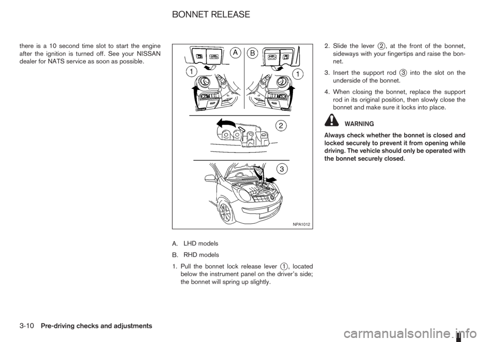
A.LHD models
B.RHD models
1. Pull the bonnet lock release lever
j1 , located
below the instrument panel on the driver’s side;
the bonnet will spring up slightly.2. Slide the lever
j2 , at the front of the bonnet,
sideways with your fingertips and raise the bon-
net.
3. Insert the support rod
j3 into the slot on the
underside of the bonnet.
4. When closing the bonnet, replace the support
rod in its original position, then slowly close the
bonnet and make sure it locks into place.
WARNING
Always check whether the bonnet is closed and
locked securely to prevent it from opening while
driving. The vehicle should only be operated with
the bonnet securely closed.
NPA1012
BONNET RELEASE
3-10Pre-driving checks and adjustments
Page 81 of 235
FUEL FILLER LID OPENER LEVER
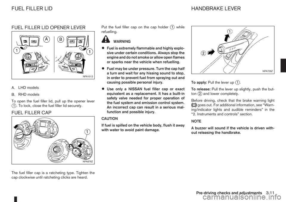
A.LHD models
B.RHD models
To open the fuel filler lid, pull up the opener lever
j1 . To lock, close the fuel filler lid securely.
FUEL FILLER CAP
The fuel filler cap is a ratcheting type. Tighten the
cap clockwise until ratcheting clicks are heard.Put the fuel filler cap on the cap holder
j1 while
refuelling.
WARNING
•Fuel is extremely flammable and highly explo-
sive under certain conditions. Always stop the
engine and do not smoke or allow open flames
or sparks near the vehicle when refuelling.
•Fuel may be under pressure. Turn the cap half
a turn and wait for any hissing sound to stop,
in order to prevent fuel from spraying out and
causing possible personal injury.
•Use only a NISSAN fuel filler cap or exact
equivalent as a replacement. It has a built-in
safety valve needed for proper operation of
the fuel system and emission control system.
An incorrect cap can result in a serious mal-
function and possible injury.
CAUTION
If fuel is spilled on the vehicle body, flush it away
with water to avoid paint damage.To apply:Pull the lever up
j1.
To release:Pull the lever up slightly, push the but-
ton
j2 and lower completely.
Before driving, check that the brake warning light
goes out. For additional information, see “Warn-
ing/indicator lights and audible reminders” in the
“2. Instruments and controls” section.
NOTE
A buzzer will sound if the vehicle is driven with-
out releasing the handbrake.
NPA1013
NPA876Z
NPA728Z
FUEL FILLER LID HANDBRAKE LEVER
Pre-driving checks and adjustments3-11
Page 86 of 235
SIDE VENTS
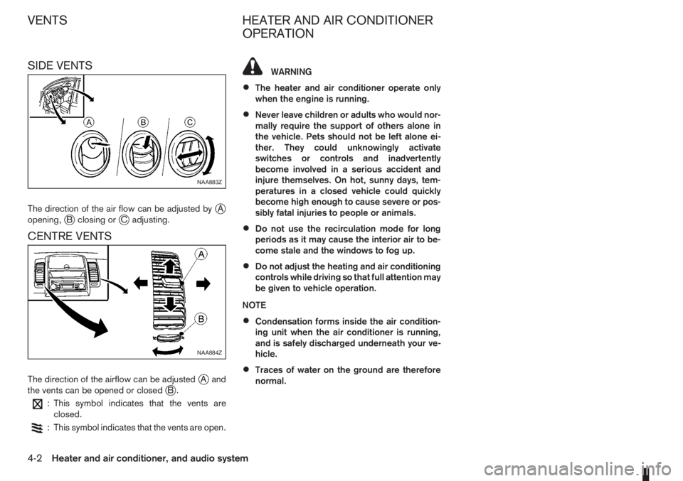
The direction of the air flow can be adjusted byjA
opening,jB closing orjC adjusting.
CENTRE VENTS
The direction of the airflow can be adjustedjAand
the vents can be opened or closedjB.
: This symbol indicates that the vents are
closed.
: This symbol indicates that the vents are open.
WARNING
•The heater and air conditioner operate only
when the engine is running.
•Never leave children or adults who would nor-
mally require the support of others alone in
the vehicle. Pets should not be left alone ei-
ther. They could unknowingly activate
switches or controls and inadvertently
become involved in a serious accident and
injure themselves. On hot, sunny days, tem-
peratures in a closed vehicle could quickly
become high enough to cause severe or pos-
sibly fatal injuries to people or animals.
•Do not use the recirculation mode for long
periods as it may cause the interior air to be-
come stale and the windows to fog up.
•Do not adjust the heating and air conditioning
controls while driving so that full attention may
be given to vehicle operation.
NOTE
•Condensation forms inside the air condition-
ing unit when the air conditioner is running,
and is safely discharged underneath your ve-
hicle.
•Traces of water on the ground are therefore
normal.
NAA883Z
NAA884Z
VENTS HEATER AND AIR CONDITIONER
OPERATION
4-2Heater and air conditioner, and audio system
Page 87 of 235
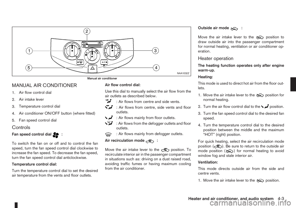
MANUAL AIR CONDITIONER
1.Air flow control dial
2.Air intake lever
3.Temperature control dial
4.Air conditioner ON/OFF button (where fitted)
5.Fan speed control dial
Controls
Fan speed control dialm:
To switch the fan on or off and to control the fan
speed, turn the fan speed control dial clockwise to
increase the fan speed. To decrease the fan speed,
turn the fan speed control dial anticlockwise.
Temperature control dial:
Turn the temperature control dial to set the desired
air temperature from the vents and floor outlets.Air flow control dial:
Use this dial to manually select the air flow from the
air outlets as described below.
: Air flows from centre and side vents.
: Air flows from centre, side vents and floor
outlets.
: Air flows mainly from floor outlets.
: Air flows from the defogger outlets and floor
outlets.
: Air flows mainly from defogger outlets.
Air recirculation mode
m:
Move the air intake lever to the
position. To
recirculate interior air in the passenger compartment
in situations such as: driving on a dust raised road,
avoiding traffic fumes or having maximum cooling
from the air conditioner.Outside air mode
m:
Move the air intake lever to the
position to
draw outside air into the passenger compartment
for normal heating, ventilation or air conditioner op-
eration.
Heater operation
The heating function operates only after engine
warm-up.
Heating:
This mode is used to direct hot air from the floor out-
lets.
1. Move the air intake lever to the
position for
normal heating.
2. Turn the air flow control dial to the
position.
3. Turn the fan speed control dial to the desired fan
speed.
4. Turn the temperature control dial to the desired
position between the middle and the maximum
“HOT” (right) position.
For quick heating, select the air recirculation mode
position (
). Be sure to return to the outside air
mode position () for normal heating to avoid
window fog and stale interior air.
Ventilation:
This mode directs outside air from the side and
centre vents.
1. Move the air intake lever to the
position.
NAA1032Z
Manual air conditioner
Heater and air conditioner, and audio system4-3
Page 88 of 235
2. Turn the air flow control dial to theposition.
3. Turn the fan speed control dial to the desired fan
speed.
4. Turn the temperature control dial to the desired
position.
Defrosting or defogging:
This mode is used to defrost/defog the windows.
1. Move the air intake lever to the
position.
2. Turn the air flow control dial to the
position.
3. Turn the fan speed control dial to speed position
2 or above.
4. Turn the temperature control dial to the desired
position between the middle and the maximum
“HOT” (right) position.
To quickly defrost/defog the windscreen, turn the
fan speed control dial to the maximum position and
the temperature control dial to the maximum “HOT”
(right) position.
Heating and defogging:
This mode heats the interior and defogs the wind-
screen.
1. Move the air intake lever to outside air mode
position (
).
2. Turn the air flow control dial to the
position.
3. Turn the fan speed control dial to speed position
2 or above.4. Turn the temperature control dial between the
middle and the maximum “HOT” (right) position.
Air conditioner operation (where fitted)
Start the engine, turn the fan speed control dial to
the desired fan speed and press the A/C button to
activate the air conditioner. When the air conditioner
is on, cooling and dehumidifying functions will be
added to the heater operation. To switch off the air
conditioner, press the button again.
NOTE
The air conditioner cooling function operates only
when the engine is running.
Cooling:
This mode is used to cool and dehumidify.
1. Move the air intake lever to outside air mode
position (
).
2. Turn the air flow control dial to the
position.
3. Turn the fan speed control dial to the desired fan
speed.
4. Press thebutton and the indicator light
will come on.
5. Turn the temperature control dial to the desired
position.
For quick cooling when the outside temperature is
high, select the air recirculation mode position
(
). Be sure to return to the outside air mode
position () to avoid windows from fogging-up
and interior air from becoming stale.NOTE
A visible mist may be seen coming from the vents
in hot, humid conditions as the air is cooled rap-
idly. This does not indicate a malfunction.
Dehumidified heating:
This mode is used to heat and dehumidify.
1. Move the air intake lever to outside air mode
position (
).
2. Turn the air flow control dial to the
position.
3. Turn on the fan speed control dial to the desired
fan speed.
4. Press thebutton and the indicator light
will come on.
5. Turn the temperature control dial to the desired
position.
Dehumidified defogging:
This mode is used to defog the windows and dehu-
midify.
1. Move the air intake lever to outside air mode
position (
).
2. Turn the air flow control dial to the
position.
3. Turn the fan speed control dial to the desired fan
speed.
4. Press thebutton and the indicator light
will come on.
5. Turn the temperature control dial to the desired
position.
4-4Heater and air conditioner, and audio system