mirror NISSAN NOTE 2011 Owners Manual
[x] Cancel search | Manufacturer: NISSAN, Model Year: 2011, Model line: NOTE, Model: NISSAN NOTE 2011Pages: 235, PDF Size: 2.29 MB
Page 9 of 235
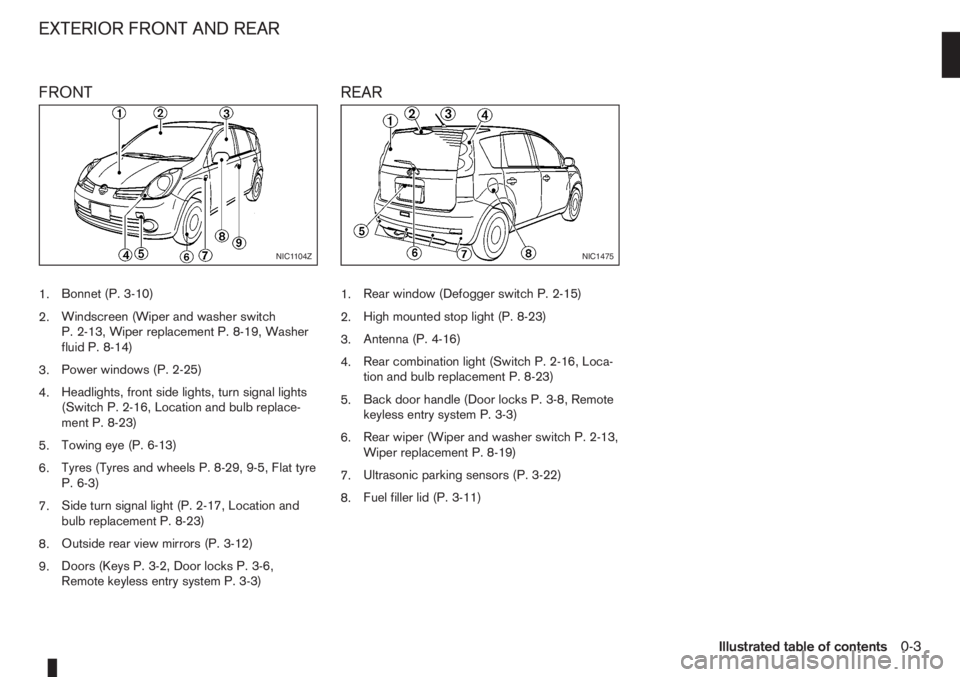
FRONT
1.Bonnet (P. 3-10)
2.Windscreen (Wiper and washer switch
P. 2-13, Wiper replacement P. 8-19, Washer
fluid P. 8-14)
3.Power windows (P. 2-25)
4.Headlights, front side lights, turn signal lights
(Switch P. 2-16, Location and bulb replace-
ment P. 8-23)
5.Towing eye (P. 6-13)
6.Tyres (Tyres and wheels P. 8-29, 9-5, Flat tyre
P. 6-3)
7.Side turn signal light (P. 2-17, Location and
bulb replacement P. 8-23)
8.Outside rear view mirrors (P. 3-12)
9.Doors (Keys P. 3-2, Door locks P. 3-6,
Remote keyless entry system P. 3-3)
REAR
1.Rear window (Defogger switch P. 2-15)
2.High mounted stop light (P. 8-23)
3.Antenna (P. 4-16)
4.Rear combination light (Switch P. 2-16, Loca-
tion and bulb replacement P. 8-23)
5.Back door handle (Door locks P. 3-8, Remote
keyless entry system P. 3-3)
6.Rear wiper (Wiper and washer switch P. 2-13,
Wiper replacement P. 8-19)
7.Ultrasonic parking sensors (P. 3-22)
8.Fuel filler lid (P. 3-11)
NIC1104ZNIC1475
EXTERIOR FRONT AND REAR
Illustrated table of contents0-3
Page 11 of 235
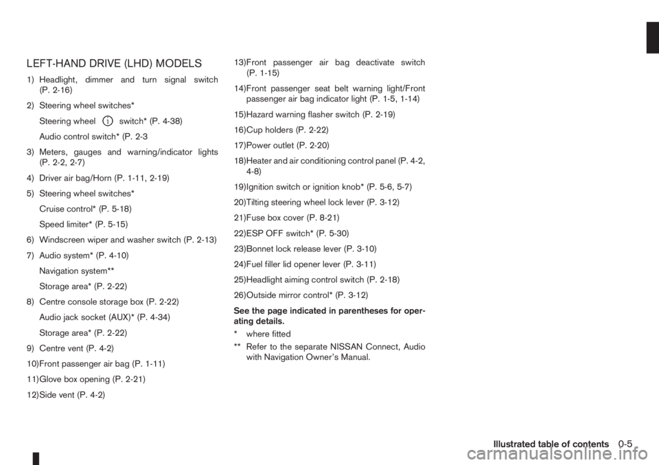
LEFT-HAND DRIVE (LHD) MODELS
1) Headlight, dimmer and turn signal switch
(P. 2-16)
2) Steering wheel switches*
Steering wheel
switch* (P. 4-38)
Audio control switch* (P. 2-3
3) Meters, gauges and warning/indicator lights
(P. 2-2, 2-7)
4) Driver air bag/Horn (P. 1-11, 2-19)
5) Steering wheel switches*
Cruise control* (P. 5-18)
Speed limiter* (P. 5-15)
6) Windscreen wiper and washer switch (P. 2-13)
7) Audio system* (P. 4-10)
Navigation system**
Storage area* (P. 2-22)
8) Centre console storage box (P. 2-22)
Audio jack socket (AUX)* (P. 4-34)
Storage area* (P. 2-22)
9) Centre vent (P. 4-2)
10)Front passenger air bag (P. 1-11)
11)Glove box opening (P. 2-21)
12)Side vent (P. 4-2)13)Front passenger air bag deactivate switch
(P. 1-15)
14)Front passenger seat belt warning light/Front
passenger air bag indicator light (P. 1-5, 1-14)
15)Hazard warning flasher switch (P. 2-19)
16)Cup holders (P. 2-22)
17)Power outlet (P. 2-20)
18)Heater and air conditioning control panel (P. 4-2,
4-8)
19)Ignition switch or ignition knob* (P. 5-6, 5-7)
20)Tilting steering wheel lock lever (P. 3-12)
21)Fuse box cover (P. 8-21)
22)ESP OFF switch* (P. 5-30)
23)Bonnet lock release lever (P. 3-10)
24)Fuel filler lid opener lever (P. 3-11)
25)Headlight aiming control switch (P. 2-18)
26)Outside mirror control* (P. 3-12)
See the page indicated in parentheses for oper-
ating details.
* where fitted
** Refer to the separate NISSAN Connect, Audio
with Navigation Owner’s Manual.
Illustrated table of contents0-5
Page 13 of 235
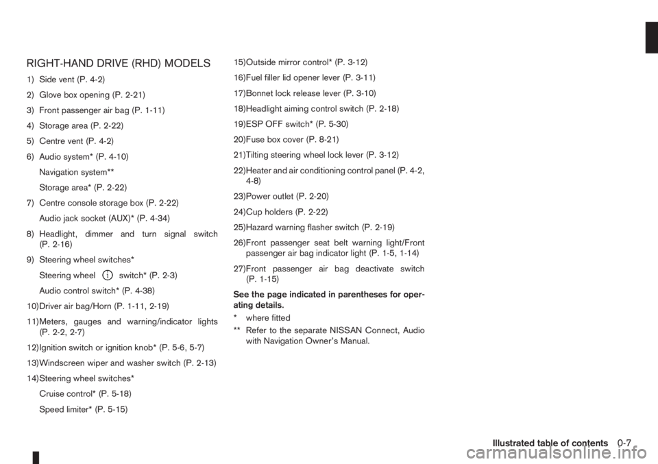
RIGHT-HAND DRIVE (RHD) MODELS
1) Side vent (P. 4-2)
2) Glove box opening (P. 2-21)
3) Front passenger air bag (P. 1-11)
4) Storage area (P. 2-22)
5) Centre vent (P. 4-2)
6) Audio system* (P. 4-10)
Navigation system**
Storage area* (P. 2-22)
7) Centre console storage box (P. 2-22)
Audio jack socket (AUX)* (P. 4-34)
8) Headlight, dimmer and turn signal switch
(P. 2-16)
9) Steering wheel switches*
Steering wheel
switch* (P. 2-3)
Audio control switch* (P. 4-38)
10)Driver air bag/Horn (P. 1-11, 2-19)
11)Meters, gauges and warning/indicator lights
(P. 2-2, 2-7)
12)Ignition switch or ignition knob* (P. 5-6, 5-7)
13)Windscreen wiper and washer switch (P. 2-13)
14)Steering wheel switches*
Cruise control* (P. 5-18)
Speed limiter* (P. 5-15)15)Outside mirror control* (P. 3-12)
16)Fuel filler lid opener lever (P. 3-11)
17)Bonnet lock release lever (P. 3-10)
18)Headlight aiming control switch (P. 2-18)
19)ESP OFF switch* (P. 5-30)
20)Fuse box cover (P. 8-21)
21)Tilting steering wheel lock lever (P. 3-12)
22)Heater and air conditioning control panel (P. 4-2,
4-8)
23)Power outlet (P. 2-20)
24)Cup holders (P. 2-22)
25)Hazard warning flasher switch (P. 2-19)
26)Front passenger seat belt warning light/Front
passenger air bag indicator light (P. 1-5, 1-14)
27)Front passenger air bag deactivate switch
(P. 1-15)
See the page indicated in parentheses for oper-
ating details.
* where fitted
** Refer to the separate NISSAN Connect, Audio
with Navigation Owner’s Manual.
Illustrated table of contents0-7
Page 43 of 235
2Instruments and controlsInstruments and controls
Meters and gauges .................................................. 2-2
Speedometer...................................................... 2-2
Tachometer ........................................................ 2-2
Fuel gauge ......................................................... 2-2
Combination meter display (LCD) ....................... 2-3
Odometer/twin trip odometer .............................. 2-3
Trip computer (where fitted)................................ 2-3
Outside temperature display ............................... 2-4
Engine oil level information (where fitted)............. 2-4
Digital clock ........................................................ 2-5
Warning/indicator lights and audible reminders ........ 2-7
Checking bulbs .................................................. 2-7
Warning lights .................................................... 2-7
Indicator lights .................................................... 2-11
Audible reminders............................................... 2-12
Wiper and washer switch ........................................ 2-13
Windscreen wiper and washer switch ................. 2-13
Rear window ...................................................... 2-14
Defogger switch ...................................................... 2-15
Rear window defogger ....................................... 2-15
Outside mirror defogger (where fitted) ................ 2-15
Headlight and turn signal switch............................... 2-16
Headlight switch ................................................. 2-16
Turn signal switch ............................................... 2-17
Fog light switch ....................................................... 2-17
Front fog light (where fitted) ................................ 2-17Rear fog light switch ........................................... 2-18
Headlight aiming control .......................................... 2-18
Headlight aiming control switch........................... 2-18
Hazard warning flasher switch ................................. 2-19
Horn ........................................................................ 2-19
Seat heating (where fitted) ....................................... 2-19
Power outlet ............................................................ 2-20
Storage ................................................................... 2-21
Glove box ........................................................... 2-21
Centre console storage box ................................ 2-22
Cup holder ......................................................... 2-22
Rear foldable tables (where fitted)....................... 2-23
Seat pockets (where fitted) ................................. 2-23
Convenience hook (where fitted)......................... 2-23
Under seat storage tray (where fitted) ................. 2-23
“Flexi-board” System (where fitted) ..................... 2-24
Utility hooks (where fitted)................................... 2-25
Power windows ....................................................... 2-25
Driver’s side main switch .................................... 2-26
Passenger’s side switch ..................................... 2-26
Automatic operation ............................................ 2-26
Interior lights ............................................................ 2-27
Room light .......................................................... 2-27
Map light (where fitted) ....................................... 2-28
Luggage compartment light ................................ 2-28
Page 57 of 235
WARNING
In freezing temperatures the washer solution
may freeze on the rear window and obscure your
vision. Warm the rear window with the rear win-
dow defogger before you wash the rear window.
NOTE
When the windscreen wiper switch is in the inter-
mittent, low or high speed position and the vehi-
cle’s gear lever is set in Reverse, the rear window
wiper comes on (where fitted).REAR WINDOW DEFOGGER
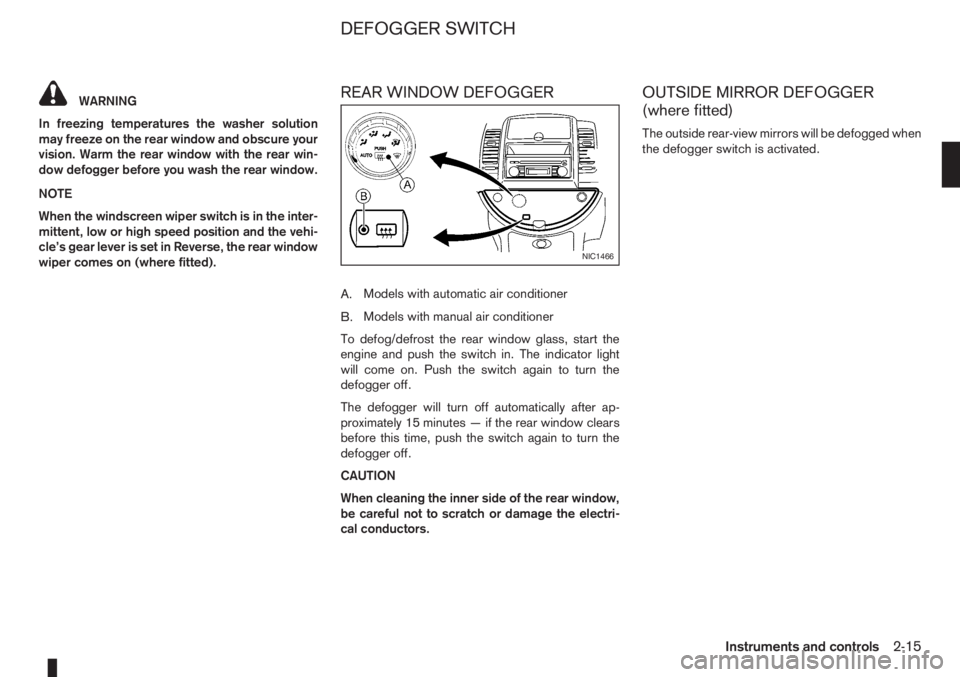
A.Models with automatic air conditioner
B.Models with manual air conditioner
To defog/defrost the rear window glass, start the
engine and push the switch in. The indicator light
will come on. Push the switch again to turn the
defogger off.
The defogger will turn off automatically after ap-
proximately 15 minutes — if the rear window clears
before this time, push the switch again to turn the
defogger off.
CAUTION
When cleaning the inner side of the rear window,
be careful not to scratch or damage the electri-
cal conductors.
OUTSIDE MIRROR DEFOGGER
(where fitted)
The outside rear-view mirrors will be defogged when
the defogger switch is activated.
NIC1466
DEFOGGER SWITCH
Instruments and controls2-15
Page 60 of 235
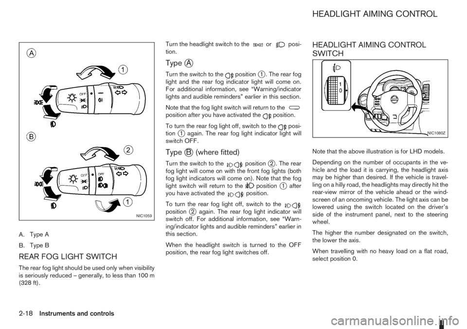
A.Type A
B.Type B
REAR FOG LIGHT SWITCH
The rear fog light should be used only when visibility
is seriously reduced – generally, to less than 100 m
(328 ft).Turn the headlight switch to the
orposi-
tion.
TypejA
Turn the switch to thepositionj1 . The rear fog
light and the rear fog indicator light will come on.
For additional information, see “Warning/indicator
lights and audible reminders” earlier in this section.
Note that the fog light switch will return to the
position after you have activated theposition.
To turn the rear fog light off, switch to the
posi-
tionj1 again. The rear fog light indicator light will
switch OFF.
TypejB (where fitted)
Turn the switch to thepositionj2 . The rear
fog light will come on with the front fog lights (both
fog light indicators will come on). Note that the fog
light switch will return to the
positionj1 after
you have activated theposition.
To turn the rear fog light off, switch to the
positionj2 again. The rear fog light indicator will
switch off. For additional information, see “Warn-
ing/indicator lights and audible reminders” earlier in
this section.
When the headlight switch is turned to the OFF
position, the rear fog light switches off.
HEADLIGHT AIMING CONTROL
SWITCH
Note that the above illustration is for LHD models.
Depending on the number of occupants in the ve-
hicle and the load it is carrying, the headlight axis
may be higher than desired. If the vehicle is travel-
ling on a hilly road, the headlights may directly hit the
rear-view mirror of the vehicle ahead or the wind-
screen of an oncoming vehicle. The light axis can be
lowered using the switch located on the driver’s
side of the instrument panel, next to the steering
wheel.
The higher the number designated on the switch,
the lower the axis.
When travelling with no heavy load on a flat road,
select position 0.
NIC1059
NIC1080Z
HEADLIGHT AIMING CONTROL
2-18Instruments and controls
Page 71 of 235
3Pre-driving checks and adjustmentsPre-driving checks and adjustments
Keys ........................................................................ 3-2
Integrated keyfob/remote control system .................. 3-3
Using the remote keyless entry system ................ 3-3
Locking the doors ............................................... 3-3
Unlocking the doors – convenience mode ........... 3-4
Unlocking the doors – anti-hijack mode ............... 3-4
Switching from convenience mode to
anti-hijack mode.................................................. 3-4
Keyfob operation failure ...................................... 3-4
Intelligent Key system (where fitted) ......................... 3-5
Locking/unlocking .............................................. 3-5
Starting the engine with the Intelligent Key .......... 3-6
Door locks ............................................................... 3-6
Super Lock System (Right-hand drive models) .... 3-6
Vehicle dead battery – left-hand side door
handle ................................................................ 3-7
Locking with power door lock switch .................. 3-7Child safety rear door lock .................................. 3-8
Back door lock ................................................... 3-8
Security system ....................................................... 3-9
NISSAN Anti-Theft System (NATS)..................... 3-9
Bonnet release ........................................................ 3-10
Fuel filler lid ............................................................. 3-11
Fuel filler lid opener lever .................................... 3-11
Fuel filler cap ...................................................... 3-11
Handbrake lever ...................................................... 3-11
Tilting steering wheel ............................................... 3-12
Mirrors..................................................................... 3-12
Inside rear-view mirror ........................................ 3-12
Outside rear-view mirrors.................................... 3-12
Vanity mirror ....................................................... 3-13
Rear parcel shelf...................................................... 3-14
Rear parcel shelf removal.................................... 3-14
Rear parcel shelf installation................................ 3-14
Page 82 of 235
WARNING
Do not adjust the steering wheel while driving.
You could lose control of your vehicle and cause
an accident.
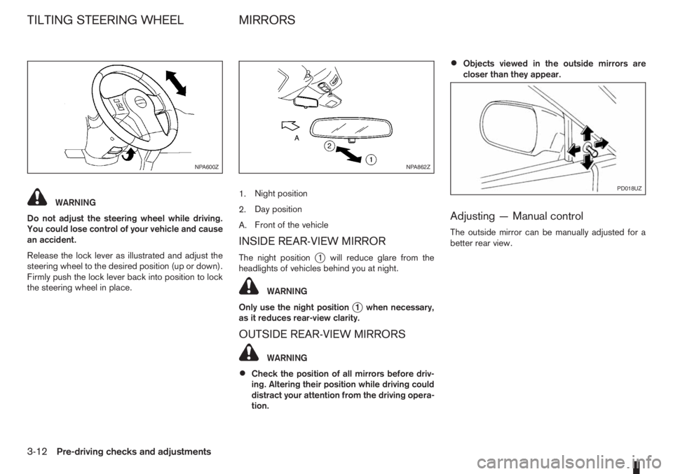
Release the lock lever as illustrated and adjust the
steering wheel to the desired position (up or down).
Firmly push the lock lever back into position to lock
the steering wheel in place.1.Night position
2.Day position
A.Front of the vehicle
INSIDE REAR-VIEW MIRROR
The night positionj1 will reduce glare from the
headlights of vehicles behind you at night.
WARNING
Only use the night position
j1 when necessary,
as it reduces rear-view clarity.
OUTSIDE REAR-VIEW MIRRORS
WARNING
•Check the position of all mirrors before driv-
ing. Altering their position while driving could
distract your attention from the driving opera-
tion.
•Objects viewed in the outside mirrors are
closer than they appear.
Adjusting — Manual control
The outside mirror can be manually adjusted for a
better rear view.
NPA600ZNPA862Z
PD018UZ
TILTING STEERING WHEEL MIRRORS
3-12Pre-driving checks and adjustments
Page 83 of 235
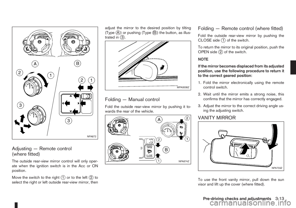
Adjusting — Remote control
(where fitted)
The outside rear-view mirror control will only oper-
ate when the ignition switch is in the Acc or ON
position.
Move the switch to the right
j1 or to the leftj2to
select the right or left outside rear-view mirror, thenadjust the mirror to the desired position by tilting
(Type
jA ) or pushing (TypejB ) the button, as illus-
trated inj3.
Folding — Manual control
Fold the outside rear-view mirror by pushing it to-
wards the rear of the vehicle.
Folding — Remote control (where fitted)
Fold the outside rear-view mirror by pushing the
CLOSE sidej1 of the switch.
To return the mirror to its original position, push the
OPEN side
j2 of the switch.
NOTE
If the mirror becomes displaced from its adjusted
position, use the following procedure to return it
to the correct geared position:
1. Fold the mirror electronically using the remote
control switch.
2. Wait until the mirror emits a strong noise, this
confirms that the mirror has correctly engaged.
3. Adjust the mirror to the correct driving angle us-
ing the adjusting switch.
VANITY MIRROR
To use the front vanity mirror, pull down the sun
visor and lift up the cover (where fitted).
NPA872
MPA0008Z
NPA874Z
NPA733Z
Pre-driving checks and adjustments3-13
Page 126 of 235
During the first 1,600 km (1,000 miles), follow these
recommendations for the future reliability and
economy of your new vehicle. Failure to follow the
recommendations may result in shortened engine
life and reduced engine performance.
•Avoid driving for long periods at a constant
speed, either fast or slow.
•Do not accelerate at full throttle in any gear.
•Avoid quick starts.
•Avoid hard braking as much as possible.
•Do not tow a trailer during the first 800 km (500
miles).
NOTE
Models with K9K diesel engine will achieve top
performance only after approximately 5,000 km
(3,000 miles).
WARNING
The driving characteristics of your vehicle can be
changed remarkably by any additional load and
its distribution as well as by adding optional
equipment (trailer couplings, roof racks, etc.).
Your driving style and speed have to be adjusted
accordingly. Especially when carrying heavy
loads, your speed must be reduced adequately.
•Make sure the area around the vehicle is free of
obstacles.
•Check fluid levels such as engine oil, coolant,
brake and clutch fluid, and window washer fluid
as frequently as possible, at least whenever you
refuel.
•Visually inspect tyres for their appearance and
condition. Also check the tyre pressure for
proper inflation.
•Maintenance items in the “8. Maintenance and
do-it-yourself” section should be checked peri-
odically.
•Check that all windows and light lenses are
clean.
•Check that all doors are closed.
•Position the seat and adjust the head restraints.
•Adjust the inside and outside mirrors.
•Fasten your seat belt and ask all passengers to
do likewise.
•Check the operation of the warning/indicator
lights when the ignition switch is turned to the
ON position.
•Do not place hard or heavy objects on the dash-
board or rear parcel shelf in order to prevent
injury in the event of a sudden stop.
RUNNING-IN SCHEDULE BEFORE STARTING THE ENGINE
5-2Starting and driving