wheel NISSAN NV200 2021 User Guide
[x] Cancel search | Manufacturer: NISSAN, Model Year: 2021, Model line: NV200, Model: NISSAN NV200 2021Pages: 300, PDF Size: 1.9 MB
Page 146 of 300
Additional information:
• When using a wheel without the TPMSsuch as the spare tire, the TPMS does not
monitor the tire pressure of the spare tire.
• The TPMS will activate only when the ve- hicle is driven at speeds above 16 mph (25
km/h). Also, this system may not detect a
sudden drop in tire pressure (for example,
a flat tire while driving).
• The low tire pressure warning light does not automatically turn off when the tire
pressure is adjusted for all four tires. Af ter
all your tires are inflated to the recom-
mended pressure, the vehicle must be
driven at speeds above 16 mph (25 km/h)
to activate the TPMS and turn off the low
tire pressure warning light. Use a tire
pressure gauge to check the tire
pressure.
• The CHECK TIRE PRES (pressure) warning message is displayed in the odometer
when the low tire pressure warning light
is illuminated and low tire pressure is de-
tected. The CHECK TIRE PRES warning
message turns off when the low tire pres-
sure warning light turns off. • The low tire pressure warning light re-
mains illuminated until the tires are in-
flated to the recommended COLD tire
pressure. The CHECK TIRE PRES warning
message is displayed each time the igni-
tion switch is placed in the ON position as
long as the low tire pressure warning light
remains illuminated.
• The CHECK TIRE PRES warning message is not displayed if the low tire pressure
warning light illuminates to indicate a
TPMS malfunction.
• Tire pressure rises and falls depending on the heat caused by the vehicle’s opera-
tion and the outside temperature. Do not
reduce the tire pressure af ter driving be-
cause the tire pressure rises af ter driving.
Low outside temperature can lower the
temperature of the air inside the tire
which can cause a lower tire inflation
pressure. This may cause the low tire
pressure warning light to illuminate. If the
warning light illuminates, check the tire
pressure for all four tires.
• The Tire and Loading Information label is located in the driver's door opening.
For additional information, see “Low tire
pressure warning light” (P. 2-12) and “Tire
Pressure Monitoring System (TPMS)” (P. 6-2).
Page 147 of 300
•When using a wheel without the
TPMS such as the spare tire, when a
spare tire is mounted or a wheel is
replaced, tire pressure will not be in-
dicated, the TPMS will not function
and the low tire pressure warning
light will flash for approximately 1
minute. The light will remain on af ter
1 minute. Have your tires replaced
and/or TPMS system reset as soon as
possible. It is recommended that you
visit a NISSAN dealer for this service.
• Replacing tires with those not origi-
nally specified by NISSAN could af-
fect the proper operation of the
TPMS.
• Do not inject any tire liquid or aerosol
tire sealant into the tires, as this may
cause a malfunction of the tire pres-
sure sensors.
CAUTION
Do not place metalized film or any
metal parts (antenna, etc.) on the win-
dows. This may cause poor reception of
the signals from the tire pressure sen-
sors, and the TPMS will not function
properly. Some devices and transmitters may tem-
porarily interfere with the operation of the
TPMS and cause the low tire pressure
warning light to illuminate.
Some examples are:
• Facilities or electric devices using similar
radio frequencies are near the vehicle.
• If a transmitter set to similar frequencies is being used in or near the vehicle.
• If a computer (or similar equipment) or a DC/AC converter is being used in or near
the vehicle.
The low tire pressure warning light may
illuminate in the following cases:
• If the vehicle is equipped with a wheel and tire without TPMS.
• If the TPMS has been replaced and the ID has not been registered.
• If the wheel is not originally specified by NISSAN. FCC Notice
For USA
This device complies with Part 15 of the
FCC Rules. Operation is subject to the fol-
lowing two conditions: (1) This device
may not cause harmful interference, and
(2) this device must accept any interfer-
ence received, including interference
that may cause undesired operation.
NOTE:
Changes or modifications not ex-
pressly approved by the party re-
sponsible for compliance could void
the user's authority to operate the
equipment.
For Canada
This device complies with Industry
Canada licence-exempt RSS standard(s).
Operation is subject to the following two
conditions: (1) this device may not cause
interference, and (2) this device must ac-
cept any interference, including interfer-
ence that may cause undesired opera-
tion of the device.
Starting and driving5-5
Page 149 of 300
WARNING
The following actions can increase the
chance of losing control of the vehicle if
there is a sudden loss of tire air pres-
sure. Losing control of the vehicle may
cause a collision and result in personal
injury.
• The vehicle generally moves or pulls
in the direction of the flat tire.
• Do not rapidly apply the brakes.
• Do not rapidly release the accelerator
pedal.
• Do not rapidly turn the steering
wheel.
1. Remain calm and do not overreact.
2. Maintain a firm grip on the steering wheel with both hands and try to hold a
straight course.
3. When appropriate, slowly release the ac- celerator pedal to gradually slow the
vehicle.
4. Gradually steer the vehicle to a safe lo- cation off the road and away from traffic
if possible.
5. Lightly apply the brake pedal to gradu- ally stop the vehicle. 6. Turn on the hazard warning flashers and
contact a roadside emergency service
to change the tire. For additional infor-
mation, see “Changing a flat tire” (P. 6-3).
DRINKING ALCOHOL/DRUGS AND
DRIVING
Page 150 of 300
WARNING
• Never remove the ignition key or
place the ignition switch in the LOCK
position while driving. The steering
wheel will lock (for models with a
steering lock mechanism). This may
cause the driver to lose control of the
vehicle and could result in serious ve-
hicle damage or personal injury.
CONTINUOUSLY VARIABLE
TRANSMISSION
The ignition lock is designed so that the
ignition switch cannot be turned to the
LOCK position until the shif t lever is moved
to the P (Park) position.
• When placing the ignition switch in the LOCK position, make sure that the shif t
lever is in the P (Park) position
• When removing the key from the ignition switch (if it is inserted), make sure that the
shif t lever is in the P (Park) position. When the ignition switch cannot be placed
in the LOCK position:
1. Move the shif t lever to the P (Park)
position.
2. Move the ignition switch slightly in the ON direction.
3. Turn the ignition switch to the LOCK position.
4. Remove the key if it is inserted in the ignition switch.
If the ignition switch is placed in the LOCK
position, the shif t lever cannot be moved
from the P (Park) position.
The shif t lever can be moved if the igni-
tion switch is in the ON position and the
foot brake pedal is depressed.
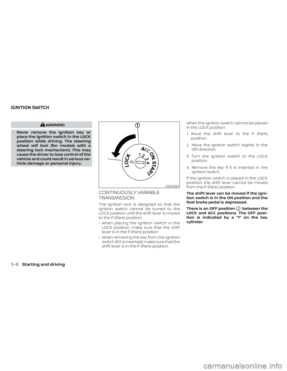
There is an OFF position
O1between the
LOCK and ACC positions. The OFF posi-
tion is indicated by a “1” on the key
cylinder.
Page 158 of 300
Accelerator downshif t
— in D (Drive) position —
For passing or hill climbing, depress the
accelerator pedal to the floor. This shif ts
the transmission down into a lower gear,
depending on the vehicle speed.
High fluid temperature protection
mode
This transmission has a high fluid tem-
perature protection mode. If the fluid tem-
perature becomes too high (for example,
when climbing steep grades in high tem-
peratures with heavy loads, such as when
towing a trailer), engine power and, under
some conditions, vehicle speed will be de-
creased automatically to reduce the
chance of transmission damage. Vehicle
speed can be controlled with the accelera-
tor pedal, but the engine and vehicle speed
may be limited.
Fail-safe
When the fail-safe operation occurs, the
Continuously Variable Transmission will
not be shif ted into the selected driving
position.If the vehicle is driven under extreme
conditions, such as excessive wheel
spinning and subsequent hard braking,
the fail-safe system may be activated.
The Malfunction Indicator Light (MIL)
may come on to indicate the fail-safe
mode is activated. For additional infor-
mation, see “Malfunction Indicator Light
(MIL)” (P. 2-14). This will occur even if all
electrical circuits are functioning prop-
erly. In this case, place the ignition switch
in the OFF position and wait for 10 sec-
onds. Then place the ignition switch
back in the ON position. The vehicle
should return to its normal operating
condition. If it does not return to its nor-
mal operating condition, have the trans-
mission checked and repaired, if neces-
sary. It is recommended that you visit a
NISSAN dealer for this service.
WARNING
When the high fluid temperature pro-
tection mode or fail-safe operation oc-
curs, vehicle speed may be gradually
reduced. The reduced speed may be
lower than other traffic, which could in-
crease the chance of a collision. Be es-
pecially careful when driving. If neces-
sary, pull to the side of the road at a safe
place and allow the transmission to re-
turn to normal operation, or have it re-
paired if necessary.
5-16Starting and driving
Page 163 of 300
WARNING
• Do not stop or park the vehicle over
flammable materials such as dry
grass, waste paper or rags. They may
ignite and cause a fire. •
Safe parking procedures require that
both the parking brake be set and the
transmission placed into P (Park).
Failure to do so could cause the ve-
hicle to move unexpectedly or roll
away and result in an accident. Make
sure the shif t lever has been pushed
as far forward as it can go and cannot
be moved without depressing the
foot brake pedal.
• Never leave the engine running while
the vehicle is unattended. •
Do not leave children unattended in-
side the vehicle. They could unknow-
ingly activate switches or controls or
make the vehicle move. Unattended
children could become involved in
serious accidents.
•
To help avoid risk of injury or death
through unintended operation of the
vehicle and/or its systems, do not
leave children, people who require the
assistance of others or pets unat-
tended in your vehicle. Additionally, the
temperature inside a closed vehicle on
a warm day can quickly become high
enough to cause a significant risk of
injury or death to people and pets.
1. Firmly apply the parking brake.
2. Move the shif t lever to the P (Park) position.
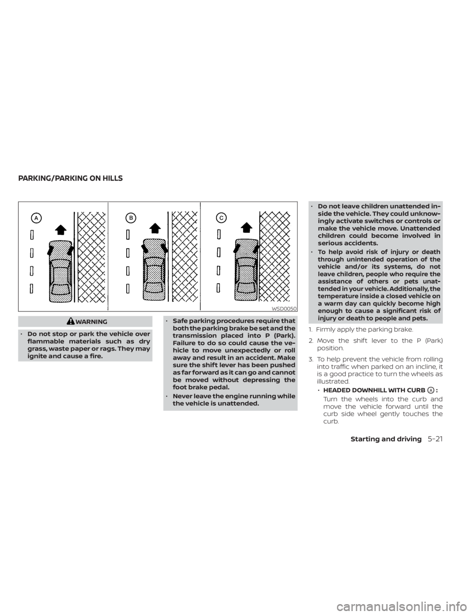
3. To help prevent the vehicle from rolling into traffic when parked on an incline, it
is a good practice to turn the wheels as
illustrated.
• HEADED DOWNHILL WITH CURB
OA:
Turn the wheels into the curb and
move the vehicle forward until the
curb side wheel gently touches the
curb.
WSD0050
PARKING/PARKING ON HILLS
Starting and driving5-21
Page 164 of 300
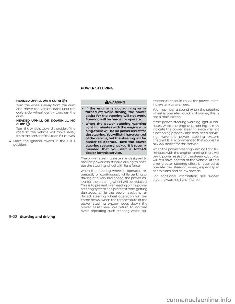
•HEADED UPHILL WITH CURBOB:
Turn the wheels away from the curb
and move the vehicle back until the
curb side wheel gently touches the
curb.
• HEADED UPHILL OR DOWNHILL, NO
CURB
OC:
Turn the wheels toward the side of the
road so the vehicle will move away
from the center of the road if it moves.
4. Place the ignition switch in the LOCK position.
Page 165 of 300
The brake system has two separate hy-
draulic circuits. If one circuit malfunctions,
you will still have braking at two wheels.
BRAKE PRECAUTIONS
Vacuum assisted brakes
The brake booster aids braking by using
engine vacuum. If the engine stops, you
can stop the vehicle by depressing the
brake pedal. However, greater foot pres-
sure on the brake pedal will be required to
stop the vehicle and stopping distance will
be longer.
Using the brakes
Avoid resting your foot on the brake pedal
while driving. This will overheat the brakes,
wear out the brake pads faster, and reduce
gas mileage.
To help reduce brake wear and to prevent
the brakes from overheating, reduce speed
and downshif t to a lower gear before going
down a slope or long grade. Overheated
brakes may reduce braking performance
and could result in loss of vehicle control.
Page 166 of 300
•Tire type and condition may also af-
fect braking effectiveness.
– When replacing tires, install the
specified size of tires on all four
wheels.
– When installing a spare tire, make
sure that it is the proper size and
type as specified on the Tire and
Loading Information label. For ad-
ditional information, see “Tire and
Loading Information label”
(P. 8-31).
– For additional information, see
“Wheels and tires” (P. 8-29).
The ABS controls the brakes so the wheels
do not lock during hard braking or when
braking on slippery surfaces. The system
detects the rotation speed at each wheel
and varies the brake fluid pressure to pre-
vent each wheel from locking and sliding.
By preventing each wheel from locking, the
system helps the driver maintain steering
control and helps to minimize swerving
and spinning on slippery surfaces.Using the system
Depress the brake pedal and hold it down.
Depress the brake pedal with firm steady
pressure, but do not pump the brakes. The
Anti-lock Braking System will operate to
prevent the wheels from locking up. Steer
the vehicle to avoid obstacles.
Page 168 of 300
When the VDC OFF switch is used to turn off
the system, the VDC system still operates
to prevent one drive wheel from slipping by
transferring power to a non-slipping drive
wheel. The
indicator light flashes if this
occurs. All other VDC functions are off and
the
indicator light will not flash.
The VDC system is automatically reset to
ON when the ignition switch is placed in the
OFF position then back to the ON position.
The computer has a built-in diagnostic fea-
ture that tests the system each time you
start the engine and move the vehicle for-
ward or in reverse at a slow speed. When
the self-test occurs, you may hear a clunk
noise and/or feel a pulsation in the brake
pedal. This is normal and is not an indica-
tion of a malfunction.
indicator light may flash
or theindicator light may
illuminate.
• If brake related parts such as brake
pads, rotors and calipers are not
NISSAN recommended or are ex-
tremely deteriorated, the VDC sys-
tem may not operate properly and
both the
andindicator
lights may illuminate.
• If engine control related parts are not
NISSAN recommended or are ex-
tremely deteriorated, both the
and theindicator lights may
illuminate. •
When driving on extremely inclined
surfaces such as higher banked cor-
ners, the VDC system may not oper-
ate properly and the
indicator
light may flash or theindicator
light may illuminate. Do not drive on
these types of roads.
• When driving on an unstable surface
such as a turntable, ferry, elevator or
ramp, the
indicator light may
flash or theindicator light may
illuminate. This is not a malfunction.
Restart the engine af ter driving onto
a stable surface.
• If wheels or tires other than the
NISSAN recommended ones are
used, the VDC system may not oper-
ate properly and the
indicator
light may flash or theindicator
light may illuminate.
• The VDC system is not a substitute
for winter tires or tire chains on a
snow covered road.
RISE-UP AND BUILD-UP
The system gradually adjusts braking
power during normal braking to help pro-
vide an enhanced brake feel.
5-26Starting and driving