tow NISSAN PATHFINDER 2008 R51 / 3.G Owners Manual
[x] Cancel search | Manufacturer: NISSAN, Model Year: 2008, Model line: PATHFINDER, Model: NISSAN PATHFINDER 2008 R51 / 3.GPages: 448, PDF Size: 6.06 MB
Page 9 of 448

1. Engine hood (P. 3-20)
2. Windshield wiper and washer switch
(P. 2-24)
3. Windshield (P. 8-20)
4. Power windows (P. 2-47)
5. Door locks, keyfob, keys, Intelligent Key
system (P. 3-4, 3-16, 3-2, 3-6)
6. Mirrors (P. 3-26)
7. Tire pressure (P. 9-11)
8. Flat tire (P. 6-2)
9. Tire chains (P. 8-40)
10. Replacing bulbs (P. 8-31)
11. Headlight and turn signal switch
(P. 2-27)
12. Fog light switch (if so equipped)
(P. 2-30)
13. Tow hooks (if so equipped) (P. 6-14)
See the page number indicated in paren-
theses for operating details.
WII0048
EXTERIOR FRONT
Illustrated table of contents0-3
ZREVIEW COPYÐ2008 Pathfinder(pat)
Owners ManualÐUSA_English(nna)
03/22/07Ðdebbie
X
Page 28 of 448
WARNING
cIf you fold the front passenger’s seat-
back flat forward to carry longer ob-
jects, be sure this cargo is properly se-
cured and not near an air bag. In a
crash, an inflating air bag might force
that object toward a person. This could
cause severe injury or even death. Se-
cure objects away from the area in
which an air bag would inflate. See
“Precautions on supplemental restraint
system” later in this section.
cNever allow anyone to ride in the cargo
area or on the front passenger’s seat
when it is in the fold-down position. Use
of these areas by passengers could re-
sult in serious injury in an accident or
sudden stop.
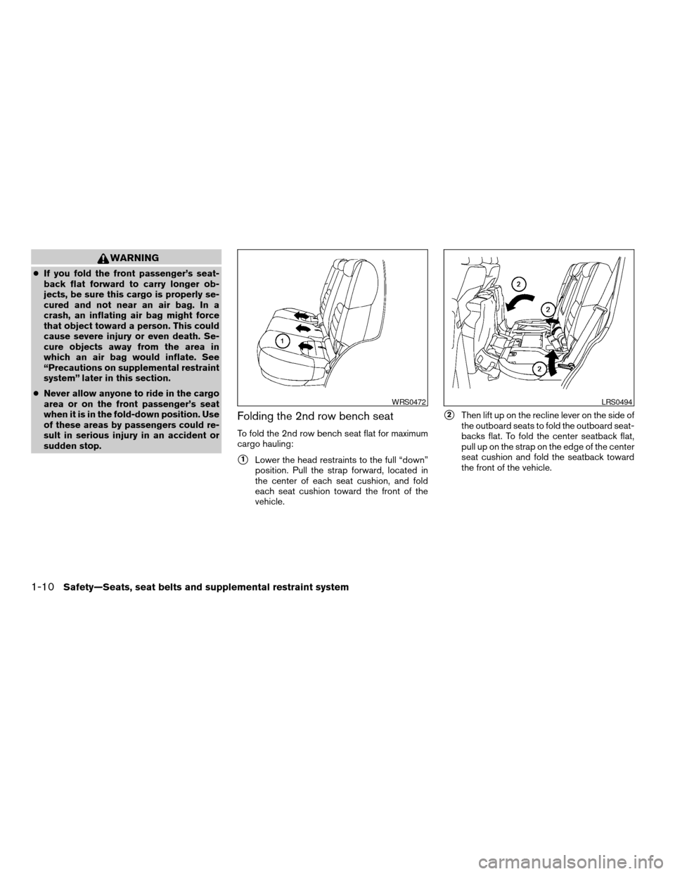
Folding the 2nd row bench seat
To fold the 2nd row bench seat flat for maximum
cargo hauling:
s1Lower the head restraints to the full “down”
position. Pull the strap forward, located in
the center of each seat cushion, and fold
each seat cushion toward the front of the
vehicle.
s2Then lift up on the recline lever on the side of
the outboard seats to fold the outboard seat-
backs flat. To fold the center seatback flat,
pull up on the strap on the edge of the center
seat cushion and fold the seatback toward
the front of the vehicle.
WRS0472LRS0494
1-10Safety—Seats, seat belts and supplemental restraint system
ZREVIEW COPYÐ2008 Pathfinder(pat)
Owners ManualÐUSA_English(nna)
03/22/07Ðdebbie
X
Page 29 of 448

s3There is a carpet panel flap on the back of
each seat that can be folded toward the
back of the vehicles4The carpet panel flap provides a level cargo
floor when the 3rd row seats are also folded
flat.
5. To return the outboard 2nd row bench seats
to a seating position reverse the process for
the outboard seats.
6. To return the center seat to a seating posi-
tion, lift up on the pull strap on the back of
the seat base while lifting on the seatback.
Then push the seat cushion back into place.
Make sure to properly raise the seat-
back to an upright position and push
the seat cushion down into place.Folding the 3rd row seats
To fold the 3rd row seats flat for maximum cargo
capacity:
1. Make sure that the head restraints are low-
ered.
2. Stow the third row seat belts in the seat belt
hooks found on the sides of the cargo area.
See “Seat belt hook” later in this section.
3. Pull up on the latch located in the upper
corner of each seatback and lower the seat-
back forward over the seat base.
LRS0658WRS0471LRS0653
Safety—Seats, seat belts and supplemental restraint system1-11
ZREVIEW COPYÐ2008 Pathfinder(pat)
Owners ManualÐUSA_English(nna)
03/22/07Ðdebbie
X
Page 35 of 448
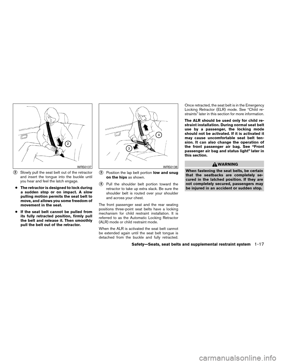
s2Slowly pull the seat belt out of the retractor
and insert the tongue into the buckle until
you hear and feel the latch engage.
cThe retractor is designed to lock during
a sudden stop or on impact. A slow
pulling motion permits the seat belt to
move, and allows you some freedom of
movement in the seat.
cIf the seat belt cannot be pulled from
its fully retracted position, firmly pull
the belt and release it. Then smoothly
pull the belt out of the retractor.s3Position the lap belt portionlow and snug
on the hipsas shown.
s4Pull the shoulder belt portion toward the
retractor to take up extra slack. Be sure the
shoulder belt is routed over your shoulder
and across your chest.
The front passenger seat and the rear seating
positions three-point seat belts have a locking
mechanism for child restraint installation. It is
referred to as the Automatic Locking Retractor
(ALR) mode or child restraint mode.
When the ALR is activated the seat belt cannot
be extended again until the seat belt tongue is
detached from the buckle and fully retracted.Once retracted, the seat belt is in the Emergency
Locking Retractor (ELR) mode. See “Child re-
straints” later in this section for more information.
The ALR should be used only for child re-
straint installation. During normal seat belt
use by a passenger, the locking mode
should not be activated. If it is activated it
may cause uncomfortable seat belt ten-
sion. It can also change the operation of
the front passenger air bag. See “Front
passenger air bag and status light” later in
this section.
WARNING
When fastening the seat belts, be certain
that the seatbacks are completely se-
cured in the latched position. If they are
not completely secured, passengers may
be injured in an accident or sudden stop.WRS0137WRS0138
Safety—Seats, seat belts and supplemental restraint system1-17
ZREVIEW COPYÐ2008 Pathfinder(pat)
Owners ManualÐUSA_English(nna)
03/22/07Ðdebbie
X
Page 54 of 448
cDo not use towels, books, pillows or
other items in place of a booster seat.
Items such as these may move during
normal driving or a collision and result
in serious injury or death. Booster seats
are designed to be used with a
lap/shoulder belt. Booster seats are de-
signed to properly route the lap and
shoulder portions of the seat belt over
the strongest portions of a child’s body
to provide the maximum protection dur-
ing a collision.
cFollow all of the booster seat manufac-
turer’s instructions for installation and
use. When purchasing a booster seat,
be sure to select one which will fit your
child and vehicle. It may not be possible
to properly install some types of
booster seats in your vehicle.
cIf the booster seat and seat belt is not
used properly, the risk of a child being
injured in a collision or a sudden stop
greatly increases.
cAdjustable seatbacks should be posi-
tioned to fit the booster seat, but as
upright as possible.cAfter placing the child in the booster
seat and fastening the seat belt, make
sure the shoulder portion of the belt is
away from the child’s face and neck and
the lap portion of the belt does not
cross the abdomen.
cDo not put the shoulder belt behind the
child or under the child’s arm. If you
must install a booster seat in the front
seat, see “Booster seat installation”
later in this section.
cWhen your booster seat is not in use,
keep it secured with a seat belt to pre-
vent it from being thrown around in
case of a sudden stop or accident.
CAUTION
Remember that a booster seat left in a
closed vehicle can become very hot.
Check the seating surface and buckles
before placing your child in the booster
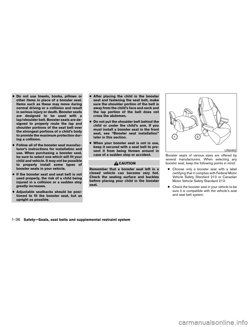
seat.Booster seats of various sizes are offered by
several manufacturers. When selecting any
booster seat, keep the following points in mind:
cChoose only a booster seat with a label
certifying that it complies with Federal Motor
Vehicle Safety Standard 213 or Canadian
Motor Vehicle Safety Standard 213.
cCheck the booster seat in your vehicle to be
sure it is compatible with the vehicle’s seat
and seat belt system.
LRS0455
1-36Safety—Seats, seat belts and supplemental restraint system
ZREVIEW COPYÐ2008 Pathfinder(pat)
Owners ManualÐUSA_English(nna)
03/22/07Ðdebbie
X
Page 57 of 448

4. Position the lap portion of the seat belt low
and snug on the child’s hips. Be sure to
follow the booster seat manufacturer’s in-
structions for adjusting the belt routing.
5. Pull the shoulder belt portion of the seat belt
toward the retractor to take up extra slack.
Be sure the shoulder belt is positioned
across the top, middle portion of the child’s
shoulder. Be sure to follow the booster seat
manufacturer’s instructions for adjusting the
belt routing.
6. Follow the warnings, cautions and instruc-
tions for properly fastening a seat belt
shown in the “Three-point seat belt with
retractor” earlier in this section.7. If the booster seat is installed in the front
passenger seat, turn the ignition switch to
the ON position. The front passenger air bag
status light
may or may not illuminate,
depending on the size of the child and the
type of booster seat being used. See “Front
passenger air bag and status light” later in
this section.
Front passenger position
LRS0454WRS0475
Safety—Seats, seat belts and supplemental restraint system1-39
ZREVIEW COPYÐ2008 Pathfinder(pat)
Owners ManualÐUSA_English(nna)
03/22/07Ðdebbie
X
Page 69 of 448
in the center of the instrument panel, will blink.
Have the system checked by a NISSAN dealer.
Other supplemental front air bag precau-
tions
WARNING
cDo not place any objects on the steer-
ing wheel pad or on the instrument
panel. Also, do not place any objects
between any occupant and the steering
wheel or instrument panel. Such ob-
jects may become dangerous projec-
tiles and cause injury if the supplemen-
tal front air bag inflates.
cImmediately after inflation, several
front air bag system components will be
hot. Do not touch them; you may se-
verely burn yourself.
cNo unauthorized changes should be
made to any components or wiring of
the supplemental air bag system. This is
to prevent accidental inflation of the
supplemental air bag or damage to the
supplemental air bag system.cDo not make unauthorized changes to
your vehicle’s electrical system, sus-
pension system or front end structure.
This could affect proper operation of
the supplemental front air bag system.
cTampering with the supplemental front
air bag system may result in serious
personal injury. Tampering includes
changes to the steering wheel and the
instrument panel assembly by placing
material over the steering wheel pad
and above the instrument panel or by
installing additional trim material
around the air bag system.
cModifying or tampering with the front
passenger seat may result in serious
personal injury. For example, do not
change the front seats by placing mate-
rial on the seat cushion or by installing
additional trim material, such as seat
covers, on the seat that are not specifi-
cally designed to assure proper air bag
operation. Additionally, do not stow any
objects under the front passenger seat
or the seat cushion and seatback. Such
objects may interfere with the proper
operation of the occupant classifica-
tion sensor (pressure sensor) .cNo unauthorized changes should be
made to any components or wiring of
the seat belt system. This may affect the
supplemental front air bag system.
Tampering with the seat belt system
may result in serious personal injury.
cWork on and around the supplemental
front air bag system should be done by
a NISSAN dealer. Installation of electri-
cal equipment should also be done by a
NISSAN dealer. The Supplemental Re-
straint System (SRS) wiring should not
be modified or disconnected. Unautho-
rized electrical test equipment and
probing devices should not be used on
the air bag system.
cA cracked windshield should be re-
placed immediately by a qualified re-
pair facility. A cracked windshield could
affect the function of the supplemental
air bag system.
cThe SRS wiring harness connectors are
yellow and orange for easy
identification.
When selling your vehicle, we request that you
inform the buyer about the supplemental front air
bag system and guide the buyer to the appropri-
ate sections in this Owner’s Manual.
Safety—Seats, seat belts and supplemental restraint system1-51
ZREVIEW COPYÐ2008 Pathfinder(pat)
Owners ManualÐUSA_English(nna)
03/22/07Ðdebbie
X
Page 87 of 448
Zone variation change procedure
The difference between magnetic north and geo-
graphical north is known as variance. In some
areas, this difference can sometimes be great
enough to cause false compass readings. Follow
these instructions to set the variance for your
particular location if this happens:
1. Press and hold the
button for about
11 seconds or thebutton for about 8
seconds. The current zone number will ap-
pear in the display. Release the button.
2. Find your current location on the zone map.
Refer to the illustration.
3. Press the
or thebutton repeat-
edly to toggle through the zone numbers
until the desired number appears in the dis-
play. Once you have selected a zone num-
ber, the display will show a compass direc-
tion within a few seconds.
Inaccurate compass direction
The compass display is equipped with automatic
correction function. If the correct direction is not
shown, follow this procedure.
1. With the display turned on, press and hold
the
button for about 13 seconds or
thefor about 10 seconds. The “C”
icon in the compass display will illuminate.2. Calibrate the compass by driving the vehicle
in three complete circles at a maximum
speed of 5 MPH (8 km/h) .
3. After completing the circles, the display
should return to normal.
CAUTION
cDo not install a ski rack, antenna, etc.,
which are attached to the vehicle by
means of a magnet. They affect the op-
eration of the compass.
cWhen cleaning the mirror, use a paper
towel or similar material dampened
with glass cleaner. Do not spray glass
cleaner directly on the mirror as it may
cause the liquid cleaner to enter the
mirror housing.
Instruments and controls2-11
ZREVIEW COPYÐ2008 Pathfinder(pat)
Owners ManualÐUSA_English(nna)
03/23/07Ðdebbie
X
Page 90 of 448
cAll mode 4WD: The warning light may
come on when the ignition switch is ON
and the automatic transmission lever is
shifted to the P position while shifting
the transfer case between 4H and 4LO.
Shift the 4WD shift switch to the 2WD,
AUTO, 4H, or 4LO position again to turn
off the ATP warning light when the
warning light comes on. (Before shift-
ing the 4WD switch into the 4LO posi-
tion or out of 4LO in the 4H position,
move the automatic transmission se-
lector lever into the N position.) Shift
the selector lever into the P position
and make sure that the 4WD shift indi-
cator light is ON and the ATP warning
light is OFF.)
This light indicates that the automatic transmis-
sion parking function is not engaged. If the trans-
fer control is not secured in any drive position
while the automatic transmission selector lever is
in the P (Park) position, the transmission will
disengage and the drive wheels will not lock.
orBrake warning light
This light functions for both the parking brake and
the foot brake systems.Parking brake indicator
When the ignition key is in the ON position, the
light comes on when the parking brake is applied.
Low brake fluid warning light
When the ignition key is in the ON position, the
light warns of a low brake fluid level. If the light
comes on while the engine is running with the
parking brake not applied, stop the vehicle and
perform the following:
1. Check the brake fluid level. Add brake fluid
as necessary. See “Brake fluid” in the “Main-
tenance and do-it-yourself” section of this
manual.
2. If the brake fluid level is correct, have the
warning system checked by a NISSAN
dealer.
WARNING
cYour brake system may not be working
properly if the warning light is on. Driv-
ing could be dangerous. If you judge it
to be safe, drive carefully to the nearest
service station for repairs. Otherwise,
have your vehicle towed because driv-
ing it could be dangerous.cPressing the brake pedal with the en-
gine stopped and/or a low brake fluid
level may increase your stopping dis-
tance and braking will require greater
pedal effort as well as pedal travel.
cIf the brake fluid level is below the
MINIMUM or MIN mark on the brake
fluid reservoir, do not drive until the
brake system has been checked at a
NISSAN dealer.
Charge warning light
If this light comes on while the engine is running,
it may indicate the charging system is not func-
tioning properly. Turn the engine off and check
the generator belt. If the belt is loose, broken,
missing, or if the light remains on, see a NISSAN
dealer immediately.
CAUTION
cDo not ground electrical accessories
directly to the battery terminal. Doing
so will bypass the variable control sys-
tem and the vehicle battery may not
charge completely. Refer to “Variable
voltage control system” in the “Mainte-
nance and do-it-yourself” section later
in this manual.
2-14Instruments and controls
ZREVIEW COPYÐ2008 Pathfinder(pat)
Owners ManualÐUSA_English(nna)
03/23/07Ðarosenma
X
Page 95 of 448

For front passenger air bag status light operation,
see “Front passenger air bag and status light” in
the “Safety — Seats, seat belts and supplemental
restraint system” section of this manual.
High beam indicator light
(blue)
This blue light comes on when the headlight high
beams are on and goes out when the low beams
are selected.
The high beam indicator light also comes on
when the passing signal is activated.
Hill descent control system on
indicator light (if so equipped)
When the ignition switch is turned ON, this light
comes on briefly and then turns off.
The light comes on when the hill descent control
system is activated.
If the hill descent control switch is on and the
indicator light blinks, the system is not engaged.
If the indicator light does not come on or blink
when the hill descent switch is on, the system
may not be functioning properly. Have the system
checked by a NISSAN dealer.For additional information, see “Hill descent con-
trol switch” later in this section and “Hill descent
control system” in the “Starting and driving” sec-
tion of this manual.
Malfunction indicator light
(MIL)
If this indicator light comes on steady or blinks
while the engine is running, it may indicate a
potential emission control malfunction.
The malfunction indicator light may also come on
steady if the fuel-filler cap is loose or missing, or if
the vehicle runs out of fuel. Check to make sure
the fuel-filler cap is installed and closed tightly,
and that the vehicle has at least 3 gallons (11.4
liters) of fuel in the fuel tank.
After a few driving trips, the
light should
turn off if no other potential emission control
system malfunction exists.
If this indicator light comes on steady for 20
seconds and then blinks for 10 seconds when
the engine is not running, it indicates that the
vehicle is not ready for an emission control sys-
tem inspection/maintenance test. See “Readi-
ness for inspection/maintenance (I/M) test” in the
“Technical and consumer information” section of
this manual.Operation
The malfunction indicator light will come on in
one of two ways:
cMalfunction indicator light on steady — An
emission control system malfunction has
been detected. Check the fuel-filler cap. If
the fuel-filler cap is loose or missing, tighten
or install the cap and continue to drive the
vehicle. The
light should turn off after
a few driving trips. If thelight does not
turn off after a few driving trips, have the
vehicle inspected by a NISSAN dealer. You
do not need to have your vehicle towed to
the dealer.
cMalfunction indicator light blinking — An en-
gine misfire has been detected which may
damage the emission control system. To re-
duce or avoid emission control system dam-
age:
– do not drive at speeds above 45 MPH
(72 km/h) .
– avoid hard acceleration or deceleration.
– avoid steep uphill grades.
– if possible, reduce the amount of cargo
being hauled or towed.
Instruments and controls2-19
ZREVIEW COPYÐ2008 Pathfinder(pat)
Owners ManualÐUSA_English(nna)
03/23/07Ðdebbie
X