radio controls NISSAN PATHFINDER 2023 Owners Manual
[x] Cancel search | Manufacturer: NISSAN, Model Year: 2023, Model line: PATHFINDER, Model: NISSAN PATHFINDER 2023Pages: 665, PDF Size: 4.64 MB
Page 126 of 665
Low tire pressure warning
If the vehicle is being driven with low tire
pressure, the warning light will illumi-
nate. A “Tire Pressure Low - Add Air”
warning also appears in the vehicle in-
formation display.
When the low tire pressure warning light
illuminates, you should stop and adjust
the tire pressure of all four tires to the
recommended COLD tire pressure shown
on the Tire and Loading Information la-
bel located in the driver's door opening.
The low tire pressure warning light does
not automatically turn off when the tire
pressure is adjusted. Af ter the tire is in-
flated to the recommended pressure,
the vehicle must be driven at speeds
above 16 mph (25 km/h) to activate the
TPMS and turn off the low tire pressure
warning light. Use a tire pressure gauge
to check the tire pressure.
The “Tire Pressure Low - Add Air” warning
appears each time the ignition switch is
placed in the ON position as long as the low
tire pressure warning light remains
illuminated.For additional information, see “Vehicle in-
formation display–7 inch (18 cm) Type A”
(P. 2-23) or “Vehicle information display—12.3
inch (31 cm) Type B” (P. 2-48), “Tire Pressure
Monitoring System (TPMS)” (P. 5-5) or (P. 6-3).
TPMS malfunction
If the TPMS is not functioning properly, the
low tire pressure warning light will flash for
approximately 1 minute when the ignition
switch is placed in the ON position. The
light will remain on af ter 1 minute. Have the
system checked. It is recommended that
you visit a NISSAN dealer for this service.
The "Tire Pressure Low — Add Air" warning
does not appear if the low tire pressure
warning light illuminates to indicate a
TPMS malfunction.
For additional information, see “Tire Pres-
sure Monitoring System (TPMS)” (P. 5-5) and
“Tire pressure” (P. 8-28).
WARNING
• Radio waves could adversely affect
electric medical equipment. Those
who use a pacemaker should contact
the electric medical equipment
manufacturer for the possible influ-
ences before use.
• If the light does not illuminate with
the ignition switch placed in the ON
position, have the vehicle checked as
soon as possible. It is recommended
that you visit a NISSAN dealer for this
service.
Instruments and controls2-19
Page 204 of 665
–– Speed Limit Sign
–– Audio
–– TEL/SMS
• Reset
NOTE:
• Emergency information may display even if the HUD is turned off.
• If the HUD is turned off, the settings items are grayed out and cannot be
modified until the HUD is turned back
on.
This product includes the following
sof tware.
(1) Panasonic Corporation or sof tware de-
veloped for Panasonic Corporation
(2) Third-party sof tware licensed to Pana-
sonic Corporation
(3) Open source sof tware
Regarding (3) Open source sof tware, it in-
cludes open source sof tware (OSS), includ-
ing various sof tware to which license infor-
mation applies.
Refer to the license web site at:
http://car.panasonic.jp/oss/i02lln39.
DRIVER ASSISTANCE/NAVIGATION
LINKING
The HUD will display driver assistance and
navigation information.
The driver assistance display will show
warning situations for the following sys-
tems:
• Automatic Emergency Braking (AEB) with Pedestrian Detection
• Lane Departure Warning (LDW)
• Intelligent Forward Collision Warning (IFCW)
• Hands-free warning (for vehicles with ProPILOT Assist) (if so equipped)
• Traffic Sign Recognition (TSR) (if so equipped)
The navigation system linking display will
show the following items:
• Intersection names
• Arrows indicating turning direction
• Distance to the next intersection The Audio System linking display will show
the following items:
• Songs
• Radio stations
The TEL/SMS linking display will show the
following items:
• Caller’s name or phone number
Instruments and controls2-97
Page 206 of 665
– It may not be possible to make anemergency call depending on the
severity of a collision and/or
emergency.
• Park the vehicle in a safe location and
set the parking brake before operat-
ing the Emergency Call (SOS) button.
• Only use this service in case of an
emergency. There may be a penalty
for inappropriate use of the service.
• Radio waves could adversely affect
electric medical equipment. Indi-
viduals who use a pacemaker should
contact the device manufacturer re-
garding any possible effects before
using the system.
• The TCU (Telematics Control Unit) an-
tenna is installed inside the upper
central part of the instrument panel.
An occupant should not get any
closer to the antenna than specified
by the pacemaker manufacturer. The
radio waves from the TCU antenna
may adversely affect the operation
of the pacemaker while using the
NissanConnect® Services.
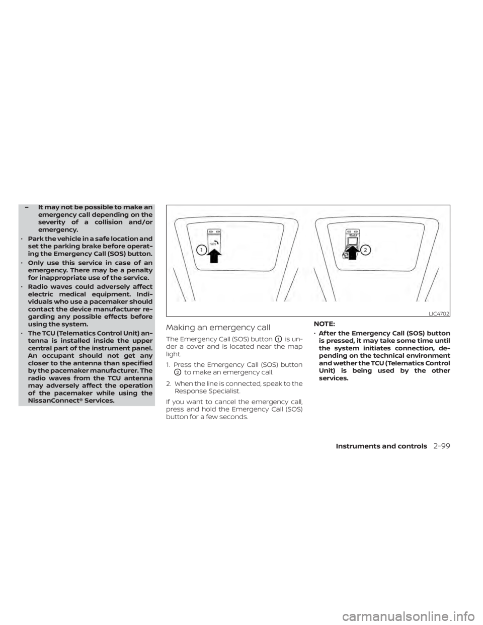
Making an emergency call
The Emergency Call (SOS) buttonO1is un-
der a cover and is located near the map
light.
1. Press the Emergency Call (SOS) button
O2to make an emergency call.
2. When the line is connected, speak to the Response Specialist.
If you want to cancel the emergency call,
press and hold the Emergency Call (SOS)
button for a few seconds.
NOTE:
• Af ter the Emergency Call (SOS) button
is pressed, it may take some time until
the system initiates connection, de-
pending on the technical environment
and wether the TCU (Telematics Control
Unit) is being used by the other
services.
LIC4702
Instruments and controls2-99
Page 212 of 665
WARNING
• Never put metallic materials be-
tween the wireless charger and a
smartphone.
• Those who use a pacemaker or other
medical equipment should contact
the electric medical equipment
manufacturer for the possible influ-
ences before use.
• Never put cloth over the smartphone
during charging process.
• Never charge a smartphone when it
is wet.
• Never put metallic materials or small
goods such as a cigarette lighter, In-
telligent Key or memory drive.
CAUTION
• Do not put an RFID/NFC/credit card
between the wireless charger and a
smartphone. This could cause data
corruption in the card.
• Do not use the wireless charger with
dust accumulated or dirt on the pad.
• Do not hit the surface of the wireless
charger. •
Do not spill liquid (water, drinks, etc.)
on the charging pad.
• Do not use grease, oil or alcohol for
cleaning charging pad.
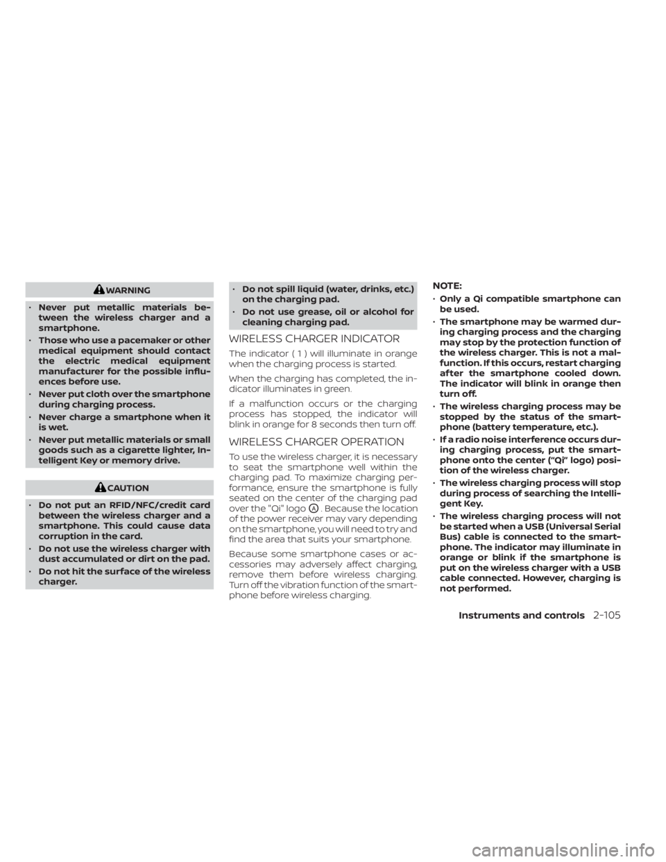
WIRELESS CHARGER INDICATOR
The indicator(1)willil luminate in orange
when the charging process is started.
When the charging has completed, the in-
dicator illuminates in green.
If a malfunction occurs or the charging
process has stopped, the indicator will
blink in orange for 8 seconds then turn off.
WIRELESS CHARGER OPERATION
To use the wireless charger, it is necessary
to seat the smartphone well within the
charging pad. To maximize charging per-
formance, ensure the smartphone is fully
seated on the center of the charging pad
over the "Qi" logo
OA. Because the location
of the power receiver may vary depending
on the smartphone, you will need to try and
find the area that suits your smartphone.
Because some smartphone cases or ac-
cessories may adversely affect charging,
remove them before wireless charging.
Turn off the vibration function of the smart-
phone before wireless charging.
NOTE:
• Only a Qi compatible smartphone can
be used.
• The smartphone may be warmed dur-
ing charging process and the charging
may stop by the protection function of
the wireless charger. This is not a mal-
function. If this occurs, restart charging
af ter the smartphone cooled down.
The indicator will blink in orange then
turn off.
• The wireless charging process may be
stopped by the status of the smart-
phone (battery temperature, etc.).
• If a radio noise interference occurs dur-
ing charging process, put the smart-
phone onto the center (“Qi” logo) posi-
tion of the wireless charger.
• The wireless charging process will stop
during process of searching the Intelli-
gent Key.
• The wireless charging process will not
be started when a USB (Universal Serial
Bus) cable is connected to the smart-
phone. The indicator may illuminate in
orange or blink if the smartphone is
put on the wireless charger with a USB
cable connected. However, charging is
not performed.
Instruments and controls2-105
Page 232 of 665
The HomeLink® Universal Transceiver pro-
vides a convenient way to consolidate the
functions of up to three individual hand-
held transmitters into one built-in device.
HomeLink® Universal Transceiver:
• Will operate most Radio Frequency (RF)devices such as garage doors, gates,
home and office lighting, entry door locks
and security systems.
• Is powered by your vehicle's battery. No separate batteries are required. If the ve-
hicle's battery is discharged or is discon-
nected, HomeLink® will retain all
programming.
When the HomeLink® Universal Trans-
ceiver is programmed, retain the original
transmitter for future programming pro-
cedures (Example: new vehicle pur-
chases). Upon sale of the vehicle, the
programmed HomeLink® Universal
Transceiver buttons should be erased for
security purposes. For additional infor-
mation, see “Programming HomeLink®”
(P. 2-125).WARNING
• Do not use the HomeLink® Universal
Transceiver with any garage door
opener that lacks safety stop and re-
verse features as required by federal
safety standards. (These standards
became effective for opener models
manufactured af ter April 1, 1982.) A
garage door opener which cannot
detect an object in the path of a clos-
ing garage door and then automati-
cally stop and reverse does not meet
current federal safety standards. Us-
ing a garage door opener without
these features increases the risk of
serious injury or death.
• During the programming procedure
your garage door or security gate will
open and close (if the transmitter is
within range). Make sure that people
or objects are clear of the garage
door, gate, etc., that you are
programming. •
Your vehicle's engine should be
turned off while programming the
HomeLink® Universal Transceiver. Do
not breathe exhaust gases; they con-
tain colorless and odorless carbon
monoxide. Carbon monoxide is dan-
gerous. It can cause unconscious-
ness or death.
PROGRAMMING HOMELINK®
The following steps show generic instruc-
tions on how to program a Homelink® but-
ton. If you have any questions or are having
difficulty programming your HomeLink®
buttons, refer to the HomeLink® web site at:
www.homelink.com/nissan or call
1-800-355-3515.
NOTE:
It is also recommended that a new bat-
tery be placed in the hand-held trans-
mitter of the device being programmed
to Homelink® for quicker programming
and accurate transmission of the
radio-frequency.
HOMELINK® UNIVERSAL
TRANSCEIVER (if so equipped)
Instruments and controls2-125
Page 235 of 665
9. If you have any questions or are havingdifficulty programming your HomeLink®
buttons, refer to the HomeLink® web site
at: www.homelink.com/nissan or call
1-800-355-3515.
PROGRAMMING HOMELINK® FOR
CANADIAN CUSTOMERS AND GATE
OPENERS
Canadian radio-frequency laws require
transmitter signals to “time-out” (or quit)
af ter several seconds of transmission –
which may not be long enough for
HomeLink® to pick up the signal during
training. Similar to this Canadian law, some
U.S. gate operators are designed to “time-
out” in the same manner.
If you live in Canada or you are having diffi-
culties training a gate operator orgarage
door opener by using the “Programming
HomeLink®” procedures, replace“Pro-
gramming HomeLink®” step 3with the
following:
NOTE:
When programming a garage door
opener, etc., unplug the device during
the “cycling” process to prevent possible
damage to the device components. Step 3: While the HomeLink® indicator light
is flashing in orange, press and release (“cy-
cling”) the hand-held transmitter button
every 2 seconds. Continue to press and
release the hand-held transmitter button
until the HomeLink® indicator light
changes from orange to green. When the
indicator light illuminates in green, the
hand-held transmitter button may be
released.
Proceed with “Programming HomeLink®”
step 4 to complete.
Remember to plug the device back in when
programming is completed.
OPERATING THE HOMELINK®
UNIVERSAL TRANSCEIVER
The HomeLink® Universal Transceiver, af ter
it is programmed, can be used to activate
the programmed device. To operate, firmly
press the appropriate programmed
HomeLink® button. The indicator light will
illuminate in green with three parenthesis
on the mirror while the signal is being
transmitted.
PROGRAMMING TROUBLE-
SHOOTING
If the HomeLink® does not quickly learn the
hand-held transmitter information:
• Replace the hand-held transmitter bat- teries with new batteries.
• Position the hand-held transmitter with its battery area facing away from the
HomeLink® button.
• Press and hold both the HomeLink® but- ton and hand-held transmitter button in
each step without interruption.
• Position the hand-held transmitter 1 to 3 in (2 to 8 cm) away from the HomeLink®
button. Hold the transmitter in that posi-
tion for up to 15 seconds. If HomeLink® is
not programmed within that time, try
holding the transmitter in another posi-
tion – for example, 6 to 12 in (15 to 20 cm)
away, keeping the HomeLink® button in
view at all times.
If you have any questions or are having
difficulty programming your HomeLink®
buttons, refer to the HomeLink® web site at:
www.homelink.com/nissan or call
1-800-355-3515.
2-128Instruments and controls
Page 320 of 665
•Heated 2nd row seat switches (if so
equipped) For additional information,
see “Heated 2nd row seat switches”
(P. 2-92).
• ON-OFF button Turns rear automatic air
conditioning system on and off.
• Air flow control buttons controls air flow
and selects the air outlet.
• AUTO button Turns rear automatic air
conditioning system on, AUTO mode on. The air conditioner system in your NISSAN
vehicle is charged with a refrigerant de-
signed with the environment in mind.
This refrigerant does not harm the
earth's ozone layer.
Special charging equipment and lubricant
is required when servicing your NISSAN air
conditioner. Using improper refrigerants or
lubricants will cause severe damage to
your air conditioner system. For additional
information, see “Air conditioner system re-
frigerant and oil recommendations”
(P. 10-8).
It is recommended that you visit a NISSAN
dealer to service your “environmentally
friendly ” air conditioner system.
WARNING
The air conditioner system contains re-
frigerant under high pressure. To avoid
personal injury, any air conditioner ser-
vice should be done only by an experi-
enced technician with proper
equipment.
ROOF MOUNTED ANTENNA
The antenna is located on the rear part of
the vehicle roof.
CAUTION
• A build-up of ice on the antenna can
affect radio performance. Remove
the ice to restore radio reception.
• When removing snow from the roof,
do not apply strong force to the an-
tenna. That may cause broken an-
tenna and roof panel dent.
• When using a high pressure car wash,
keep the high pressure nozzle away
from the antenna. The seal may be
deformed or damaged.
• The radio performance may be af-
fected if cargo carried on the roof
blocks the radio signal. If possible, do
not put cargo near the antenna.
SERVICING AIR CONDITIONER ANTENNA
Monitor, climate, audio, phone and voice recognition systems4-39
Page 650 of 665
11 Index
A
Active Brake Limited Slip (ABLS)
system....................5-180Active Ride Control.............5-181Air bag (See supplemental restraint
system).....................1-59Air bag system
Front (See supplemental front impact air
bag system)
................1-67Air bag warning labels............1-80Air bag warning light.........1-80, 2-16Air bag warning light,
supplemental.............1-80, 2-16Air cleaner...................8-17Air cleaner housing filter..........8-17Air conditionerAir conditioner operation........4-33Air conditioner specification label. .10-13Air conditioner system refrigerant and oil
recommendations............10-8Air conditioner system refrigerant
recommendations............10-8Heater and air conditioner controls. .4-33Servicing air conditioner........4-39Alarm system (See vehicle security
system).....................2-76Anchor point locations...........1-40Antenna................... .4-39Anti-lock Braking System (ABS).....5-175Antifreeze...................5-196
Approach unlock function.........3-17Armrests....................1-10Autolight switch...............2-83Automatic
Automatic power window switch. .2-119Driving with automatic transmission.5-18Automatic anti-glare inside mirror. . . .3-37Automatic brake hold............5-28Automatic door locks.............3-6Automatic Emergency Braking
(AEB)....................2-17,2-71Automatic Emergency Braking (AEB) with
Pedestrian Detection............5-137
B
Battery.................5- 196, 8-13Charge warning light...........2-15Battery replacement............8-24Key fob...................8-24NISSAN Intelligent Key®.........8-24Before starting the engine.........5-16Belt (See drive belt)..............8-15Blind Spot Warning (BSW).........5-52Booster seats.................1-56Brake
Anti-lock Braking System (ABS). . . .5-175Brake fluid..................8-11Brake light (See stop light).......8-26Brake system...............5-175
Brake warning light............2-14Brake wear indicators......2-23,8-20Parking brake operation.........5-26Self-adjusting brakes..........8-20Brake Assist.................5-177Brake fluid...................8-11Brake system................5-175Brakes.....................8-20Break-in schedule.............5-169Brightness controlInstrument panel.............2-88Bulb check/instrument panel.......2-14Bulb replacement..............8-26
C
C.M.V.S.S. certification label........10-12Camera Aiding Sonar (parking sensor).4-23Capacities and recommended
fuel/lubricants................10-2Car phone or CB radio...........4-40Cargo (See vehicle loading
information)................ .10-15Cargo area storage bin..........2-114Cargo light..................2-124Chassis control...............5-181Check tire pressure..........2-43, 2-70Child restraint with top tether strap. . .1-40Child restraints.......1-30, 1-31, 1-33, 1-35