Evaporator NISSAN PATROL 1998 Y61 / 5.G Heather And Air Conditioner Workshop Manual
[x] Cancel search | Manufacturer: NISSAN, Model Year: 1998, Model line: PATROL, Model: NISSAN PATROL 1998 Y61 / 5.GPages: 128, PDF Size: 3.77 MB
Page 13 of 128

Refrigeration Cycle
REFRIGERANT FLOW
The refrigerant ¯ow is in the standard pattern. Refrigerant ¯ows through the compressor, condenser, liquid
tank, evaporator and back to the compressor.
The refrigerant evaporation through the evaporator coil is controlled by an externally equalized expansion
valve, located inside the evaporator case.
FREEZE PROTECTION
The compressor cycles on and off to maintain the evaporator temperature within a speci®ed range. When the
evaporator coil temperature falls below a speci®ed point, the thermo control ampli®er interrupts the compres-
sor operation. When the evaporator coil temperature rises above the speci®cation, the thermo control ampli-
®er allows compressor operation.
REFRIGERANT SYSTEM PROTECTION
Dual-pressure switch
The dual-pressure switch is located on the liquid tank. If the system pressure rises or falls out of specifications,
the switch opens to interrupt compressor clutch operation.
RHA735G
DESCRIPTIONMANUAL AND AUTO
HA-11
Page 38 of 128

Trouble Diagnoses for Abnormal Pressure
Whenever system's high or low-pressure side is abnormal, diagnose using a manifold gauge. The marker
above the gauge scale in the following table indicates the standard (normal) pressure range. Since the stan-
dard (normal) pressure differs from vehicle to vehicle, refer to HA-35 (``Ambient air temperature-to-operating
pressure table'').
Gauge indication Refrigerant cycle Probable cause Corrective action
Both high and low-pressure
sides are too high.
AC359A
+Pressure is reduced soon
after water is splashed on
condenser.Excessive refrigerant charge in
refrigeration cycle.Reduce refrigerant until speci-
®ed pressure is obtained.
Air suction by cooling fan is
insufficient.Insufficient condenser cooling
performance.
¯
j
1Condenser ®ns are clogged.
j
2Improper fan rotation of
cooling fan.+Clean condenser.
+Check and repair cooling fan
as necessary.
+Low-pressure pipe is not
cold.
+When compressor is stopped
high-pressure value quickly
drops by approximately 196
kPa (2.0 bar, 2 kg/cm
2,28
psi). It then decreases gradu-
ally thereafter.Poor heat exchange in con-
denser.
(After compressor operation
stops, high pressure decreases
too slowly.)
¯
Air in refrigeration cycle.Evacuate repeatedly and
recharge system.
Engine tends to overheat. Engine cooling systems mal-
function.Check and repair each engine
cooling system.
+An area of the low-pressure
pipe is colder than areas
near the evaporator outlet.
+Plates are sometimes cov-
ered with frost.+Excessive liquid refrigerant
on low-pressure side.
+Excessive refrigerant dis-
charge ¯ow.
+Expansion valve is open a
little compared with the
speci®cation.
¯
j
1Improper thermal valve
installation.
j
2Improper expansion valve
adjustment.Replace expansion valve.
High-pressure side is too high
and low-pressure side is too
low.
AC360A
Upper side of condenser and
high-pressure side are hot,
however, liquid tank is not so
hot.High-pressure tube or parts
located between compressor
and condenser are clogged or
crushed.+Check and repair or replace
malfunctioning parts.
+Check lubricant for contami-
nation.
TROUBLE DIAGNOSESMANUAL
HA-36
Page 39 of 128

Gauge indication Refrigerant cycle Probable cause Corrective action
High-pressure side is too low
and low-pressure side is too
high.
AC356A
High and low-pressure sides
become equal soon after com-
pressor operation stops.Compressor pressure operation
is improper.
¯
Damaged inside compressor
packings.Replace compressor.
No temperature difference
between high and low-pressure
sides.Compressor pressure operation
is improper.
¯
Damaged inside compressor
packings.Replace compressor.
Both high and low-pressure
sides are too low.
AC353A
+There is a big temperature
difference between receiver
drier outlet and inlet. Outlet
temperature is extremely low.
+Liquid tank inlet and expan-
sion valve are frosted.Liquid tank inside is clogged a
little.+Replace liquid tank.
+Check lubricant for contami-
nation.
+Temperature of expansion
valve inlet is extremely low
as compared with areas near
liquid tank.
+Expansion valve inlet may be
frosted.
+Temperature difference
occurs somewhere in high-
pressure side.High-pressure pipe located
between liquid tank and expan-
sion valve is clogged.+Check and repair malfunc-
tioning parts.
+Check lubricant for contami-
nation.
+Expansion valve and liquid
tank are warm or only cool
when touched.Low refrigerant charge.
¯
Leaking ®ttings or components.Check refrigerant for leaks.
Refer to ``Checking Refrigerant
Leaks'', HA-119.
There is a big temperature dif-
ference between expansion
valve inlet and outlet while the
valve itself is frosted.Expansion valve closes a little
compared with the speci®ca-
tion.
¯
j
1Improper expansion valve
adjustment.
j
2Malfunctioning thermal
valve.
j
3Outlet and inlet may be
clogged.+Remove foreign particles by
using compressed air.
+Check lubricant for contami-
nation.
An area of the low-pressure
pipe is colder than areas near
the evaporator outlet.Low-pressure pipe is clogged
or crushed.+Check and repair malfunc-
tioning parts.
+Check lubricant for contami-
nation.
Air ¯ow volume is not enough
or is too low.Compressor pressure operation
is improper.Replace compressor.
TROUBLE DIAGNOSESMANUAL
Trouble Diagnoses for Abnormal Pressure
(Cont'd)
HA-37
Page 49 of 128
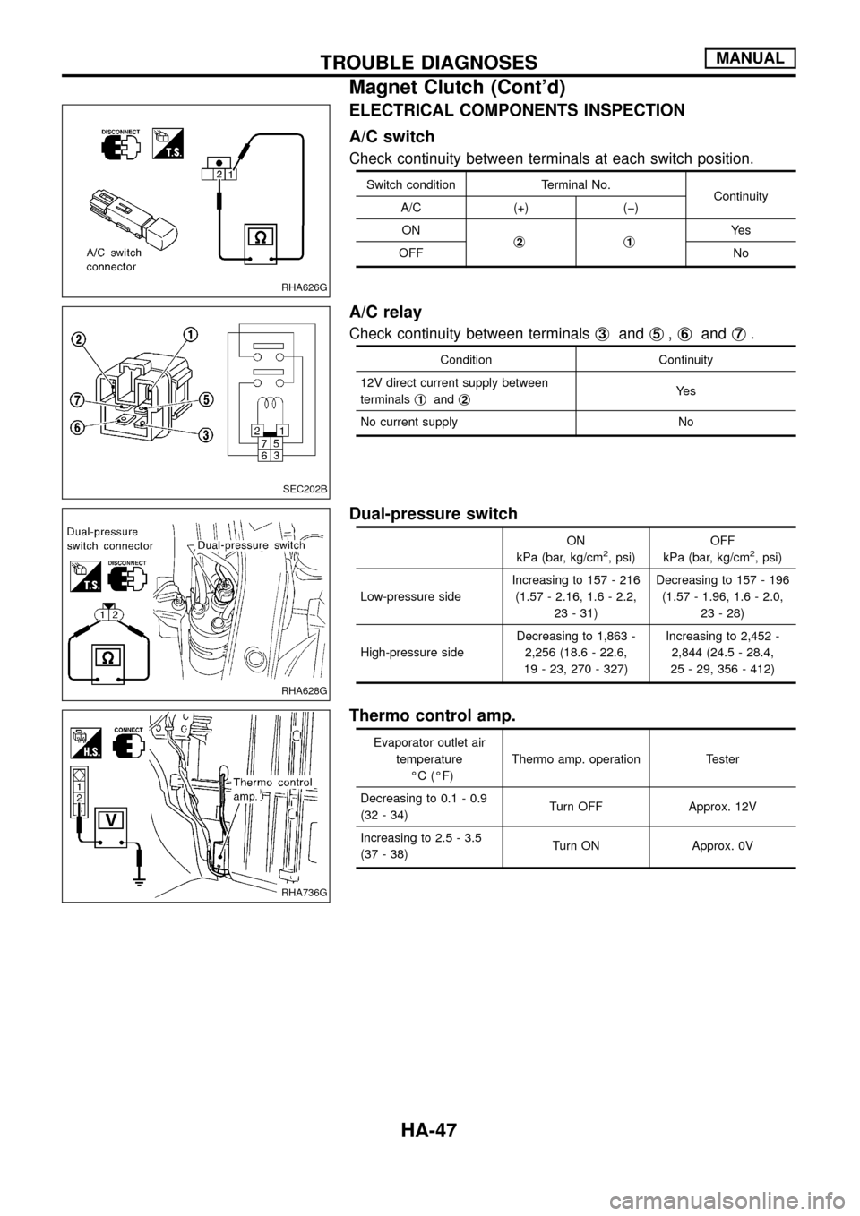
ELECTRICAL COMPONENTS INSPECTION
A/C switch
Check continuity between terminals at each switch position.
Switch condition Terminal No.
Continuity
A/C (+) (þ)
ON
j
2j1Ye s
OFF No
A/C relay
Check continuity between terminalsj3andj5,j6andj7.
Condition Continuity
12V direct current supply between
terminalsj
1andj2Ye s
No current supply No
Dual-pressure switch
ON
kPa (bar, kg/cm2, psi)OFF
kPa (bar, kg/cm2, psi)
Low-pressure sideIncreasing to 157 - 216
(1.57 - 2.16, 1.6 - 2.2,
23 - 31)Decreasing to 157 - 196
(1.57 - 1.96, 1.6 - 2.0,
23 - 28)
High-pressure sideDecreasing to 1,863 -
2,256 (18.6 - 22.6,
19 - 23, 270 - 327)Increasing to 2,452 -
2,844 (24.5 - 28.4,
25 - 29, 356 - 412)
Thermo control amp.
Evaporator outlet air
temperature
ÉC (ÉF)Thermo amp. operation Tester
Decreasing to 0.1 - 0.9
(32 - 34)Turn OFF Approx. 12V
Increasing to 2.5 - 3.5
(37 - 38)Turn ON Approx. 0V
RHA626G
SEC202B
RHA628G
RHA736G
TROUBLE DIAGNOSESMANUAL
Magnet Clutch (Cont'd)
HA-47
Page 112 of 128

Intake Sensor
COMPONENT DESCRIPTION
The intake sensor is located on the cooling unit. It converts tem-
perature of air after it passes through the evaporator into a resis-
tance value. The value is then input to the auto ampli®er.
DIAGNOSTIC PROCEDURE
SYMPTOM: Intake sensor circuit is open or shorted.
CHECK INTAKE SENSOR CIRCUIT
BETWEEN INTAKE SENSOR AND AUTO
AMP.
Disconnect intake sensor harness connec-
tor.
Do approx. 5 volts exist between intake
sensor harness terminal No.j
25and body
ground?
Ye s
cNo
Disconnect auto amp. har-
ness connector.
Note
Check circuit continuity
between intake sensor har-
ness terminal No.j
25and
auto amp. harness terminal
No.j
25.
Continuity should exist.
If OK, check harness for
short.
OK
Disconnect auto amp. harness connector.
Replace auto amp.
Note
Check circuit continuity between intake
sensor harness terminal No.j
24and auto
amp. harness terminal No.j24.
Continuity should exist.
If OK, check harness for short.
OK
CHECK INTAKE SENSOR.
(Refer to HA-111.)
OK
cNG
Replace intake sensor.
Replace auto amp.
Note:
If the result is NG or No after checking circuit continuity, repair harness
or connector.
RHA685G
RHA957FA
RHA686G
RHA687G
RHA688G
.
..
.
.
.
TROUBLE DIAGNOSESAUTO
HA-110
Page 116 of 128
Maintenance of Lubricant Quantity in
Compressor
The lubricant used to lubricate the compressor circulates through
the system with the refrigerant. Add lubricant to compressor when
replacing any component or after a large gas leakage occurred. It
is important to maintain the speci®ed amount.
If lubricant quantity is not maintained properly, the following mal-
functions may result:
+Lack of lubricant: May lead to a seized compressor
+Excessive lubricant: Inadequate cooling (thermal exchange
interference)
LUBRICANT
Name: Nissan A/C System Oil Type S
Part number: KLH00-PAGS0
CHECKING AND ADJUSTING
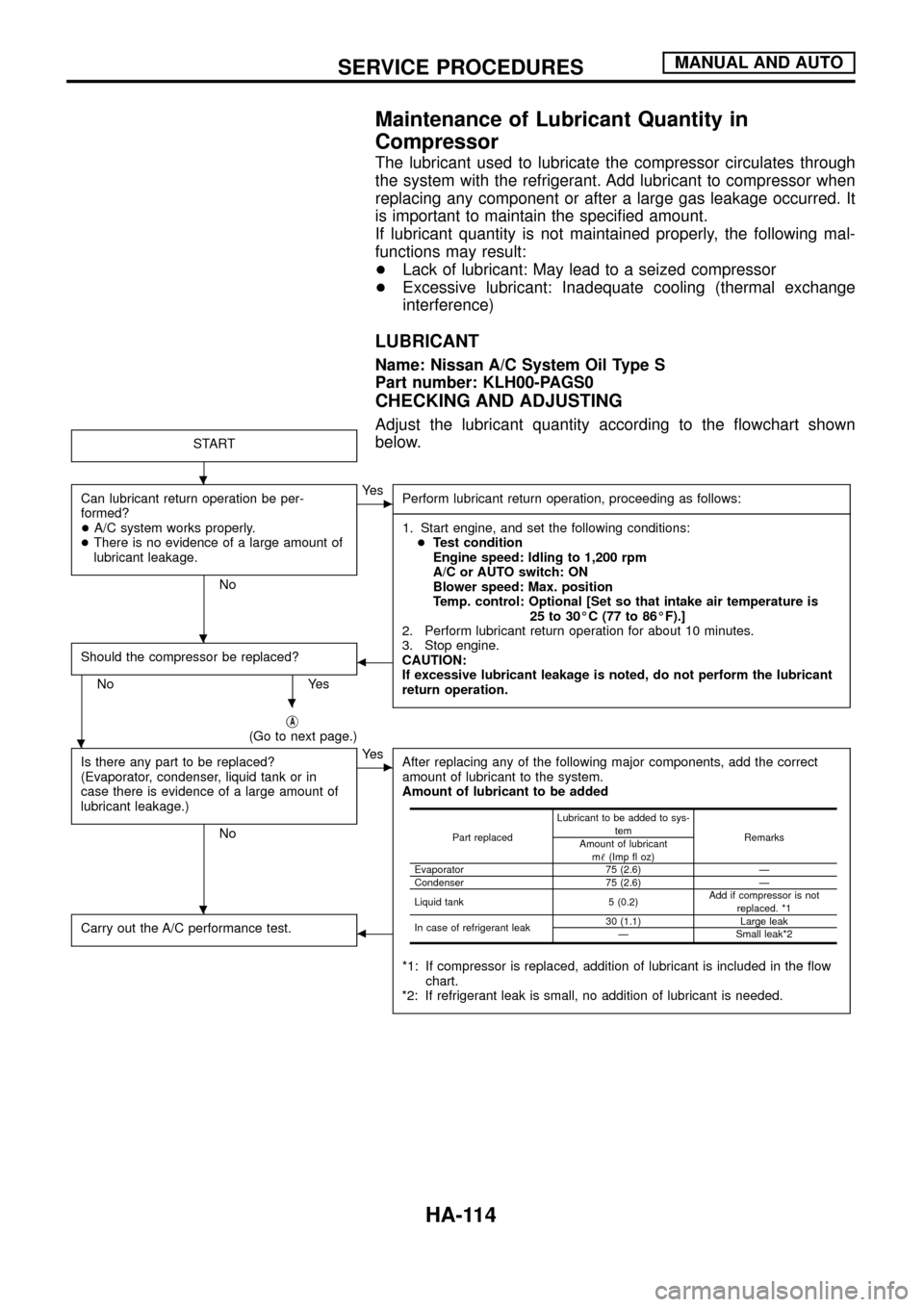
Adjust the lubricant quantity according to the ¯owchart shown
below.
START
Can lubricant return operation be per-
formed?
+A/C system works properly.
+There is no evidence of a large amount of
lubricant leakage.
No
cYe s
Perform lubricant return operation, proceeding as follows:
------------------------------------------------------------------------------------------------------------------------------------------------------------------------------------------------------------------------------------------------------------------------------------------------------------------------------------------------------------------------------------------------------------------------------------------------------------------------------------------------------------------------------------
1. Start engine, and set the following conditions:
+Test condition
Engine speed: Idling to 1,200 rpm
A/C or AUTO switch: ON
Blower speed: Max. position
Temp. control: Optional [Set so that intake air temperature is
25 to 30ÉC (77 to 86ÉF).]
2. Perform lubricant return operation for about 10 minutes.
3. Stop engine.
CAUTION:
If excessive lubricant leakage is noted, do not perform the lubricant
return operation.
Should the compressor be replaced?
No Yes
b
jA(Go to next page.)
Is there any part to be replaced?
(Evaporator, condenser, liquid tank or in
case there is evidence of a large amount of
lubricant leakage.)
No
cYe s
After replacing any of the following major components, add the correct
amount of lubricant to the system.
Amount of lubricant to be added
*1: If compressor is replaced, addition of lubricant is included in the ¯ow
chart.
*2: If refrigerant leak is small, no addition of lubricant is needed.
Carry out the A/C performance test.b
Part replacedLubricant to be added to sys-
tem
Remarks
Amount of lubricant
m!(Imp ¯ oz)
Evaporator 75 (2.6) Ð
Condenser 75 (2.6) Ð
Liquid tank 5 (0.2)Add if compressor is not
replaced. *1
In case of refrigerant leak30 (1.1) Large leak
Ð Small leak*2
.
.
.
.
.
SERVICE PROCEDURESMANUAL AND AUTO
HA-114
Page 122 of 128

3. Move probe along component approximately 25 to 50 mm (1 to
2 in)/sec.
CHECKING PROCEDURE
To prevent inaccurate or false readings, make sure there is no
refrigerant vapor or tobacco smoke in the vicinity of the
vehicle. Perform the leak test in calm area (low air/wind move-
ment) so that the leaking refrigerant is not dispersed.
1. Turn engine off.
2. Connect a suitable A/C manifold gauge set to the A/C service
ports.
3. Check if the A/C refrigerant pressure is at least 345 kPa (3.452
bar, 3.52 kg/cm
2, 50 psi) above 16ÉC (61ÉF). If less than
speci®cation, evacuate and recharge the system with the speci-
®ed amount of refrigerant.
NOTE: At temperatures below 16ÉC (61ÉF), leaks may not be
detected since the system may not reach 345 kPa
(3.452 bar, 3.52 kg/cm
2, 50 psi).
4. Conduct the leak test from the high side to the low side at points
in alphabetical order (j
a,jb......). Refer to HA-117.
Perform a leak check for the following areas carefully. Clean the
component to be checked and move the leak detector probe
completely around the connection/component.
+Compressor
Check the ®tting of high and low pressure hoses, relief valve
and shaft seal.
+Liquid tank
Check the pressure switch, tube ®tting, weld seams and the
fusible plug mounts.
+Service valves
Check all around the service valves. Ensure service valve caps
are secured on the service valves (to prevent leaks).
NOTE: After removing A/C manifold gauge set from service
valves, wipe any residue from valves to prevent any
false readings by leak detector.
+Cooling unit (Evaporator)
Turn blower fan on ``High'' for at least 15 seconds to dissipate
any refrigerant trace in the cooling unit. Insert the leak detector
probe into the drain hose immediately after stopping the
engine. (Keep the probe inserted for at least ten seconds.)
5. If a leak detector detects a leak, verify at least once by blowing
compressed air into area of suspected leak, then repeat check.
6. Do not stop when one leak is found. Continue to check for
additional leaks at all system components.
7. Start engine.
8. Set the heater A/C control as follows:
a. A/C switch ON
b. Face mode
c. Recirculation switch ON
d. Max cold temperature
e. Fan speed high
SHA708EA
SERVICE PROCEDURESMANUAL AND AUTO
Checking Refrigerant Leaks (Cont'd)
HA-120