NISSAN PATROL 1998 Y61 / 5.G Engine Lubrication And Cooling System Workshop Manual
Manufacturer: NISSAN, Model Year: 1998, Model line: PATROL, Model: NISSAN PATROL 1998 Y61 / 5.GPages: 22, PDF Size: 0.67 MB
Page 1 of 22
ENGINE LUBRICATION &
COOLING SYSTEMS
SECTION
LC
CONTENTS
PRECAUTIONS AND PREPARATION............................1
Liquid Gasket Application Procedure ..........................1
Special Service Tools ..................................................2
ENGINE LUBRICATION SYSTEM..................................3
Lubrication Circuit ........................................................3
Oil Pressure Check......................................................3
Oil Pump ......................................................................4
Oil Cooler .....................................................................7
Oil Jet...........................................................................7
Turbocharger ...............................................................8
ENGINE COOLING SYSTEM..........................................9
Cooling Circuit .............................................................9System Check..............................................................9
Water Pump ...............................................................10
Thermostat .................................................................12
Radiator .....................................................................14
Re®lling Engine Coolant ............................................14
Cooling Fan (Crankshaft driven) ...............................15
Cooling Fan (Motor driven)........................................15
Radiator (Aluminum type) ..........................................16
Overheating Cause Analysis .....................................20
SERVICE DATA AND SPECIFICATIONS (SDS)..........21
Engine Lubrication System ........................................21
Engine Cooling System .............................................21
LC
Page 2 of 22
Liquid Gasket Application Procedure
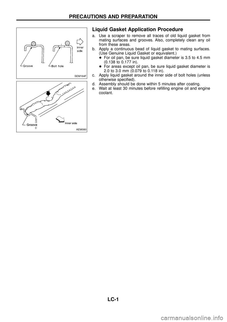
a. Use a scraper to remove all traces of old liquid gasket from
mating surfaces and grooves. Also, completely clean any oil
from these areas.
b. Apply a continuous bead of liquid gasket to mating surfaces.
(Use Genuine Liquid Gasket or equivalent.)
+For oil pan, be sure liquid gasket diameter is 3.5 to 4.5 mm
(0.138 to 0.177 in).
+For areas except oil pan, be sure liquid gasket diameter is
2.0 to 3.0 mm (0.079 to 0.118 in).
c. Apply liquid gasket around the inner side of bolt holes (unless
otherwise speci®ed).
d. Assembly should be done within 5 minutes after coating.
e. Wait at least 30 minutes before re®lling engine oil and engine
coolant.
SEM164F
AEM080
PRECAUTIONS AND PREPARATION
LC-1
Page 3 of 22
Special Service Tools*: Special tool or commercial equivalent
Tool number
Tool nameDescription
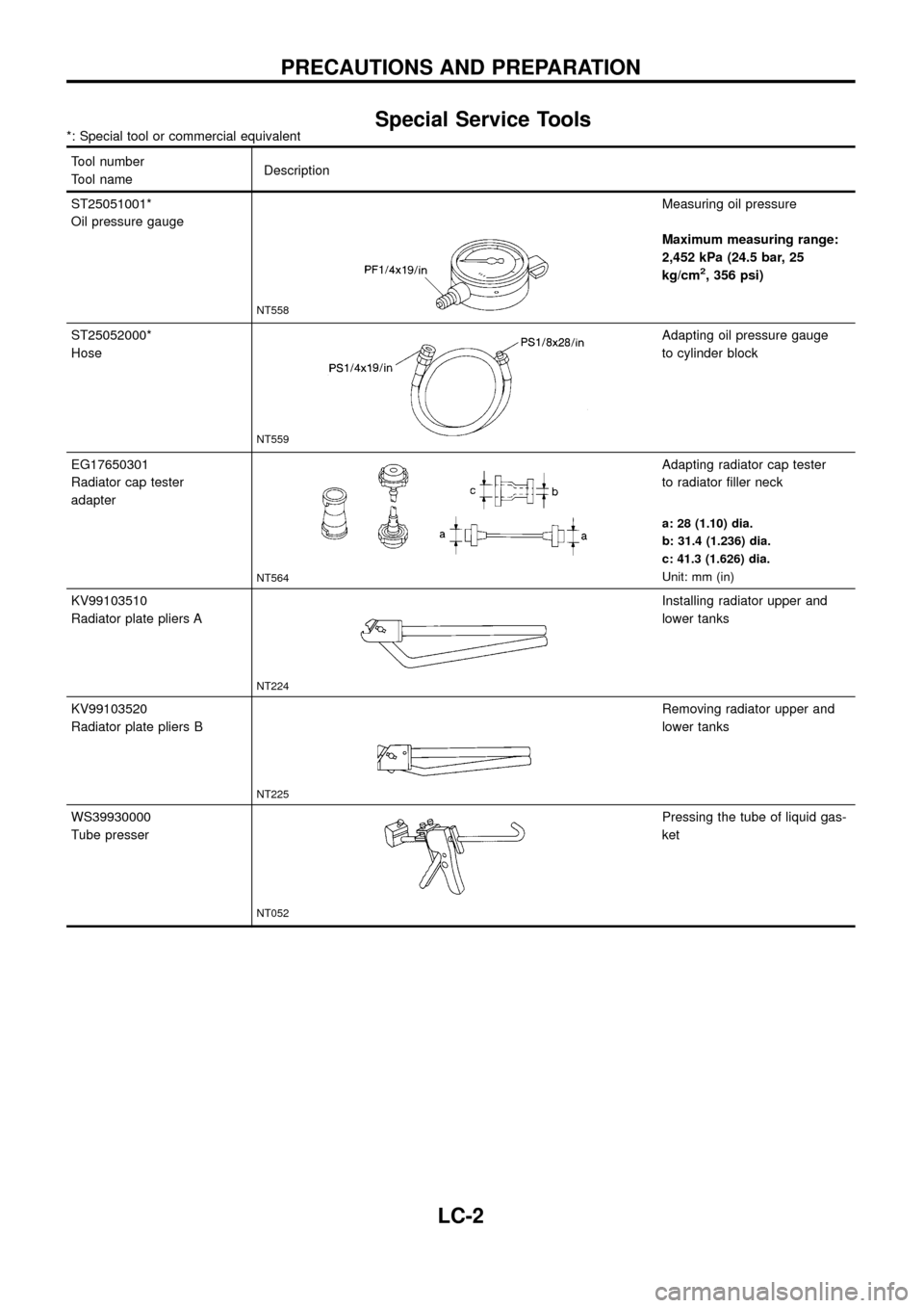
ST25051001*
Oil pressure gauge
NT558
Measuring oil pressure
Maximum measuring range:
2,452 kPa (24.5 bar, 25
kg/cm
2, 356 psi)
ST25052000*
Hose
NT559
Adapting oil pressure gauge
to cylinder block
EG17650301
Radiator cap tester
adapter
NT564
Adapting radiator cap tester
to radiator ®ller neck
a: 28 (1.10) dia.
b: 31.4 (1.236) dia.
c: 41.3 (1.626) dia.
Unit: mm (in)
KV99103510
Radiator plate pliers A
NT224
Installing radiator upper and
lower tanks
KV99103520
Radiator plate pliers B
NT225
Removing radiator upper and
lower tanks
WS39930000
Tube presser
NT052
Pressing the tube of liquid gas-
ket
PRECAUTIONS AND PREPARATION
LC-2
Page 4 of 22
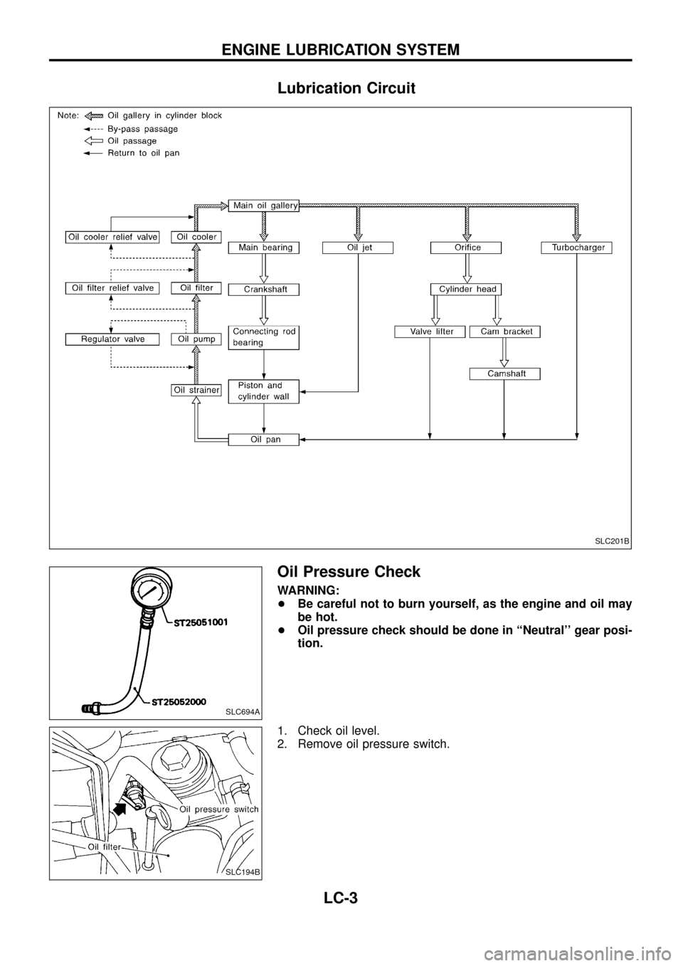
Lubrication Circuit
Oil Pressure Check
WARNING:
+Be careful not to burn yourself, as the engine and oil may
be hot.
+Oil pressure check should be done in ``Neutral'' gear posi-
tion.
1. Check oil level.
2. Remove oil pressure switch.
SLC201B
SLC694A
SLC194B
ENGINE LUBRICATION SYSTEM
LC-3
Page 5 of 22
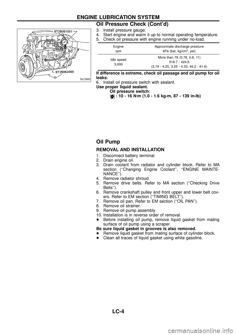
3. Install pressure gauge.
4. Start engine and warm it up to normal operating temperature.
5. Check oil pressure with engine running under no-load.
Engine
rpmApproximate discharge pressure
kPa (bar, kg/cm2, psi)
Idle speed
3,000More than 78 (0.78, 0.8, 11)
318.7 - 424.6
(3.19 - 4.25, 3.25 - 4.33, 46.2 - 61.6)
If difference is extreme, check oil passage and oil pump for oil
leaks.
6. Install oil pressure switch with sealant.
Use proper liquid sealant.
Oil pressure switch:
:10-16Nzm (1.0 - 1.6 kg-m, 87 - 139 in-lb)
Oil Pump
REMOVAL AND INSTALLATION
1. Disconnect battery terminal.
2. Drain engine oil.
3. Drain coolant from radiator and cylinder block. Refer to MA
section (``Changing Engine Coolant'', ``ENGINE MAINTE-
NANCE'').
4. Remove radiator shroud.
5. Remove drive belts. Refer to MA section (``Checking Drive
Belts'').
6. Remove crankshaft pulley and front upper and lower belt cov-
ers. Refer to EM section (``TIMING BELT'').
7. Remove oil pan. Refer to EM section (``OIL PAN'').
8. Remove oil strainer.
9. Remove oil pump assembly.
10. Installation is in reverse order of removal.
+Before installing oil pump, remove liquid gasket from mating
surface of oil pump using a scraper.
Be sure liquid gasket in grooves is also removed.
+Remove liquid gasket from mating surface of cylinder block.
+Clean all traces of liquid gasket using white gasoline.
SLC993
ENGINE LUBRICATION SYSTEM
Oil Pressure Check (Cont'd)
LC-4
Page 6 of 22
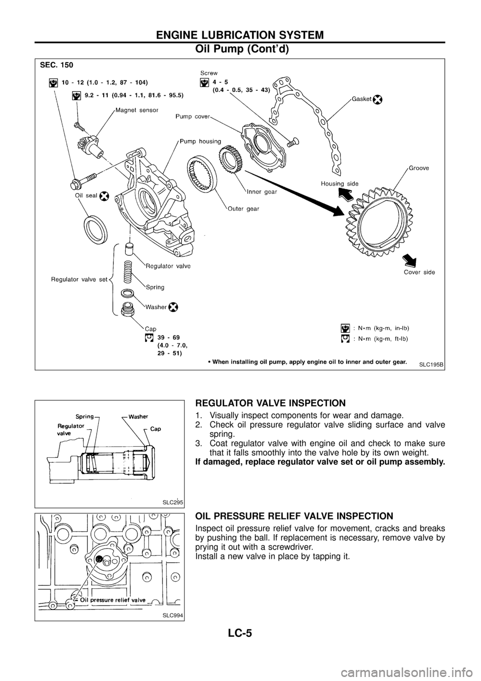
REGULATOR VALVE INSPECTION
1. Visually inspect components for wear and damage.
2. Check oil pressure regulator valve sliding surface and valve
spring.
3. Coat regulator valve with engine oil and check to make sure
that it falls smoothly into the valve hole by its own weight.
If damaged, replace regulator valve set or oil pump assembly.
OIL PRESSURE RELIEF VALVE INSPECTION
Inspect oil pressure relief valve for movement, cracks and breaks
by pushing the ball. If replacement is necessary, remove valve by
prying it out with a screwdriver.
Install a new valve in place by tapping it.
SLC195B
SLC295
SLC994
ENGINE LUBRICATION SYSTEM
Oil Pump (Cont'd)
LC-5
Page 7 of 22
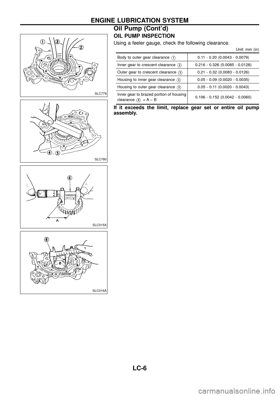
OIL PUMP INSPECTION
Using a feeler gauge, check the following clearance.
Unit: mm (in)
Body to outer gear clearanceV10.11 - 0.20 (0.0043 - 0.0079)
Inner gear to crescent clearance
V20.216 - 0.326 (0.0085 - 0.0128)
Outer gear to crescent clearance
V30.21 - 0.32 (0.0083 - 0.0126)
Housing to inner gear clearance
V40.05 - 0.09 (0.0020 - 0.0035)
Housing to outer gear clearance
V50.05 - 0.11 (0.0020 - 0.0043)
Inner gear to brazed portion of housing
clearance
V6=Aþ B0.106 - 0.152 (0.0042 - 0.0060)
If it exceeds the limit, replace gear set or entire oil pump
assembly.
SLC779
SLC780
SLC015A
SLC016A
ENGINE LUBRICATION SYSTEM
Oil Pump (Cont'd)
LC-6
Page 8 of 22
Oil Cooler
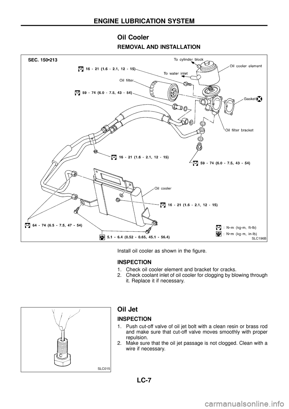
REMOVAL AND INSTALLATION
Install oil cooler as shown in the ®gure.
INSPECTION
1. Check oil cooler element and bracket for cracks.
2. Check coolant inlet of oil cooler for clogging by blowing through
it. Replace it if necessary.
Oil Jet
INSPECTION
1. Push cut-off valve of oil jet bolt with a clean resin or brass rod
and make sure that cut-off valve moves smoothly with proper
repulsion.
2. Make sure that the oil jet passage is not clogged. Clean with a
wire if necessary.
SLC196B
SLC015
ENGINE LUBRICATION SYSTEM
LC-7
Page 9 of 22
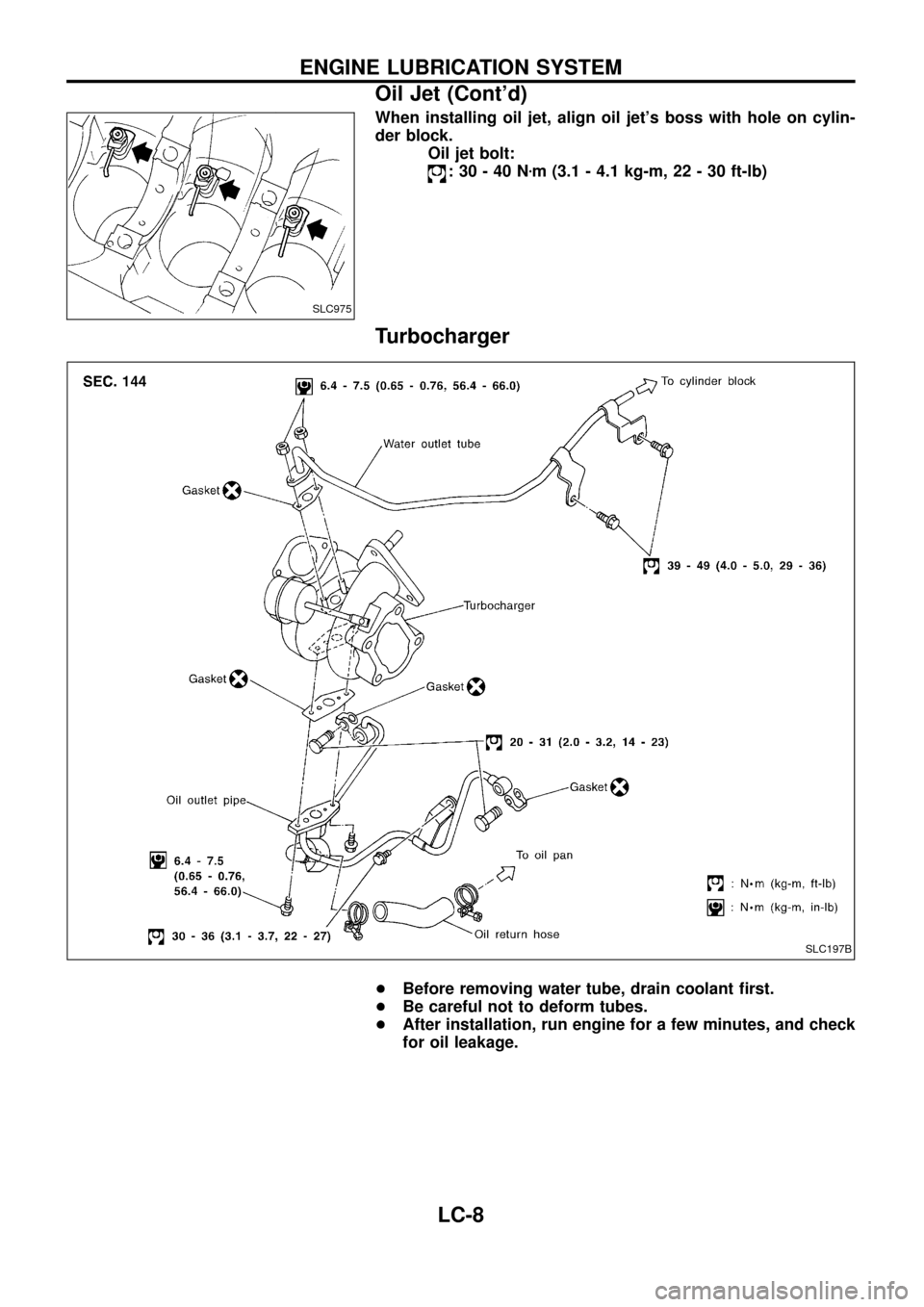
When installing oil jet, align oil jet's boss with hole on cylin-
der block.
Oil jet bolt:
:30-40Nzm (3.1 - 4.1 kg-m, 22 - 30 ft-lb)
Turbocharger
+Before removing water tube, drain coolant ®rst.
+Be careful not to deform tubes.
+After installation, run engine for a few minutes, and check
for oil leakage.
SLC975
SLC197B
ENGINE LUBRICATION SYSTEM
Oil Jet (Cont'd)
LC-8
Page 10 of 22
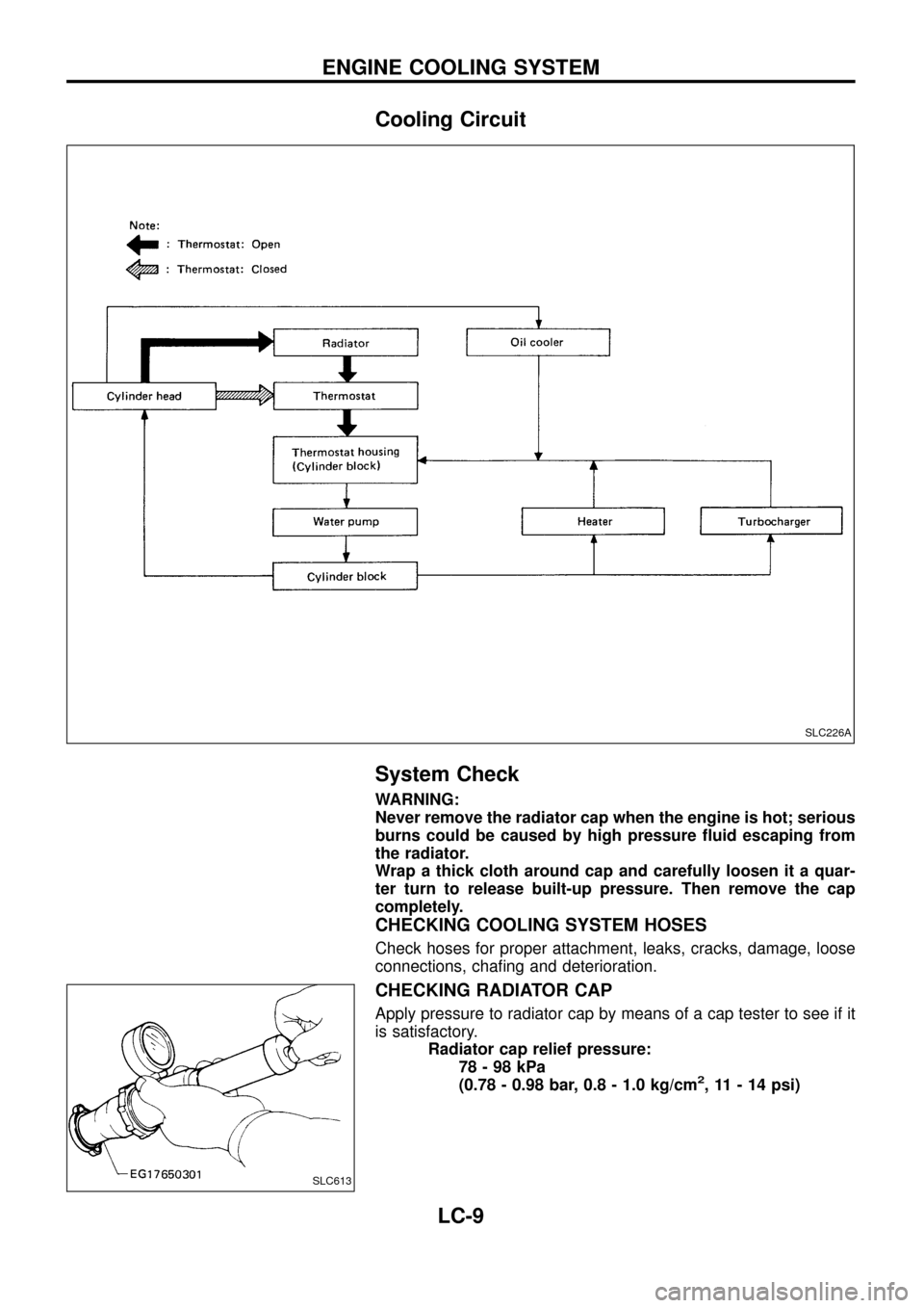
Cooling Circuit
System Check
WARNING:
Never remove the radiator cap when the engine is hot; serious
burns could be caused by high pressure ¯uid escaping from
the radiator.
Wrap a thick cloth around cap and carefully loosen it a quar-
ter turn to release built-up pressure. Then remove the cap
completely.
CHECKING COOLING SYSTEM HOSES
Check hoses for proper attachment, leaks, cracks, damage, loose
connections, cha®ng and deterioration.
CHECKING RADIATOR CAP
Apply pressure to radiator cap by means of a cap tester to see if it
is satisfactory.
Radiator cap relief pressure:
78-98kPa
(0.78 - 0.98 bar, 0.8 - 1.0 kg/cm
2, 11 - 14 psi)
SLC226A
SLC613
ENGINE COOLING SYSTEM
LC-9