Harness NISSAN PATROL 2000 Electronic Repair Manual
[x] Cancel search | Manufacturer: NISSAN, Model Year: 2000, Model line: PATROL, Model: NISSAN PATROL 2000Pages: 1033, PDF Size: 30.71 MB
Page 380 of 1033
2 CHECK BATTERY AND ALTERNATOR
Check that the proper type of battery and alternator is installed.
Refer to EL section (ªBATTERYº and ªCHARGING SYSTEMº).
OK or NG
OKcGO TO 5.
NGcReplace with a proper one.
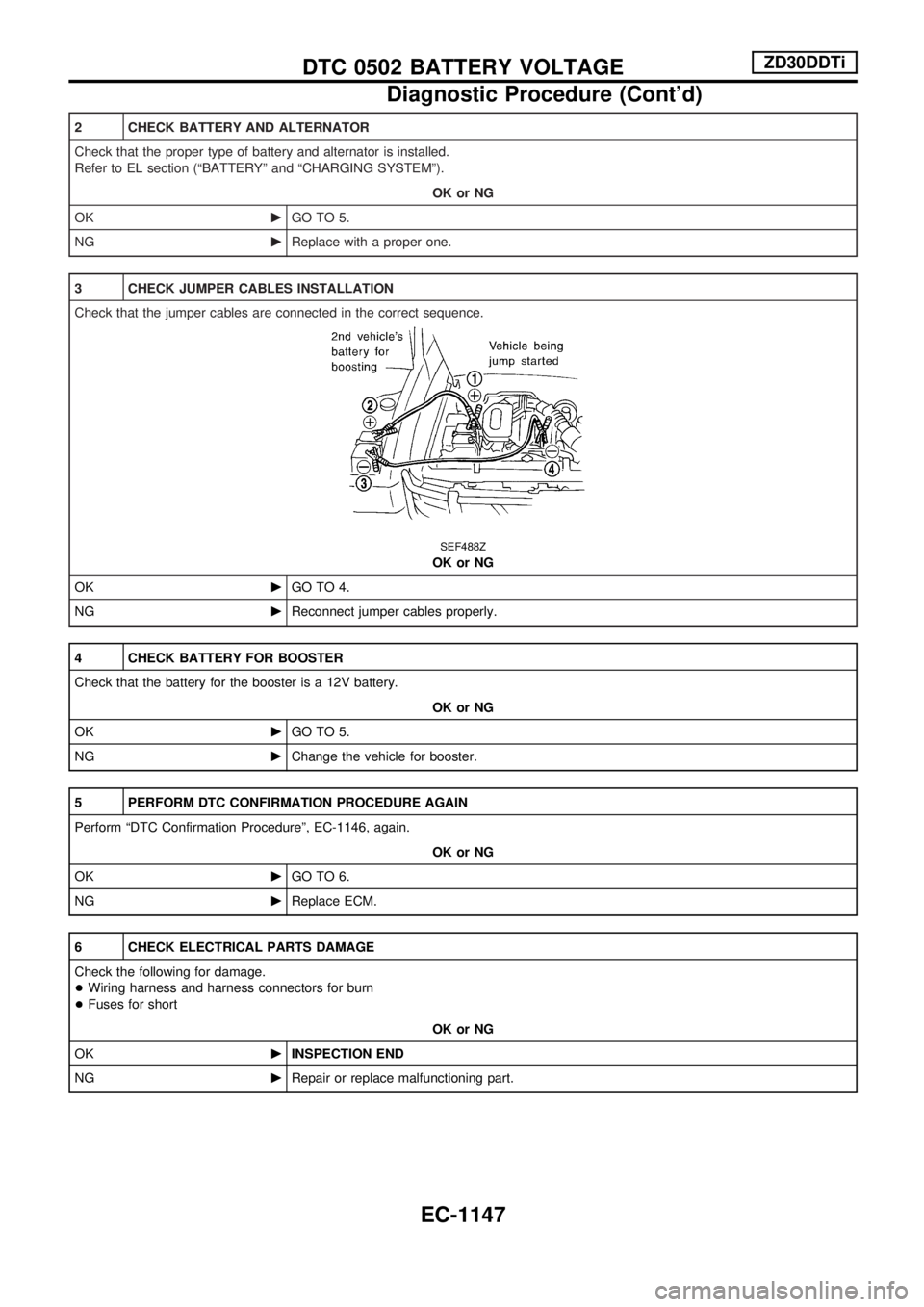
3 CHECK JUMPER CABLES INSTALLATION
Check that the jumper cables are connected in the correct sequence.
SEF488Z
OK or NG
OKcGO TO 4.
NGcReconnect jumper cables properly.
4 CHECK BATTERY FOR BOOSTER
Check that the battery for the booster is a 12V battery.
OK or NG
OKcGO TO 5.
NGcChange the vehicle for booster.
5 PERFORM DTC CONFIRMATION PROCEDURE AGAIN
Perform ªDTC Confirmation Procedureº, EC-1146, again.
OK or NG
OKcGO TO 6.
NGcReplace ECM.
6 CHECK ELECTRICAL PARTS DAMAGE
Check the following for damage.
+Wiring harness and harness connectors for burn
+Fuses for short
OK or NG
OKcINSPECTION END
NGcRepair or replace malfunctioning part.
DTC 0502 BATTERY VOLTAGEZD30DDTi
Diagnostic Procedure (Cont'd)
EC-1147
Page 381 of 1033
System Description
These circuit lines are used to control the smooth shifting up and down of A/T during the hard acceleration/
deceleration.
Voltage signals are exchanged between ECM and TCM (Transmission control module).
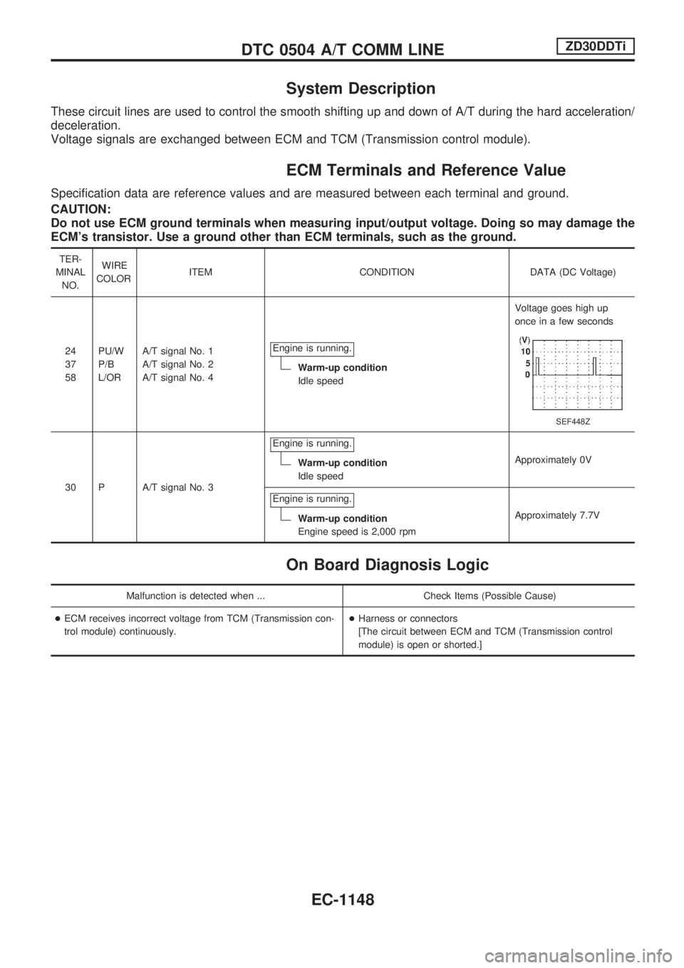
ECM Terminals and Reference Value
Specification data are reference values and are measured between each terminal and ground.
CAUTION:
Do not use ECM ground terminals when measuring input/output voltage. Doing so may damage the
ECM's transistor. Use a ground other than ECM terminals, such as the ground.
TER-
MINAL
NO.WIRE
COLORITEM CONDITION DATA (DC Voltage)
24
37
58PU/W
P/B
L/ORA/T signal No. 1
A/T signal No. 2
A/T signal No. 4Engine is running.
Warm-up condition
Idle speedVoltage goes high up
once in a few seconds
SEF448Z
30 P A/T signal No. 3Engine is running.
Warm-up condition
Idle speedApproximately 0V
Engine is running.
Warm-up condition
Engine speed is 2,000 rpmApproximately 7.7V
On Board Diagnosis Logic
Malfunction is detected when ... Check Items (Possible Cause)
+ECM receives incorrect voltage from TCM (Transmission con-
trol module) continuously.+Harness or connectors
[The circuit between ECM and TCM (Transmission control
module) is open or shorted.]
DTC 0504 A/T COMM LINEZD30DDTi
EC-1148
Page 384 of 1033
Diagnostic Procedure
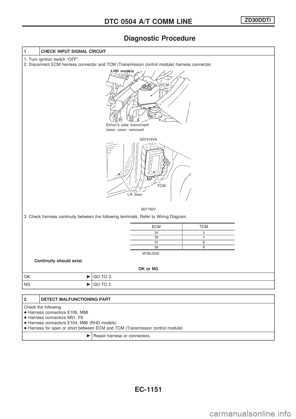
1 CHECK INPUT SIGNAL CIRCUIT
1. Turn ignition switch ªOFFº.
2. Disconnect ECM harness connector and TCM (Transmission control module) harness connector.
SEF519VA
SEF792V
3. Check harness continuity between the following terminals. Refer to Wiring Diagram.
MTBL0532
Continuity should exist.
OK or NG
OKcGO TO 3.
NGcGO TO 2.
2 DETECT MALFUNCTIONING PART
Check the following.
+Harness connectors E106, M88
+Harness connectors M51, F6
+Harness connectors E104, M86 (RHD models)
+Harness for open or short between ECM and TCM (Transmission control module)
cRepair harness or connectors.
DTC 0504 A/T COMM LINEZD30DDTi
EC-1151
Page 385 of 1033
3 CHECK INPUT SIGNAL CIRCUIT
1. Check harness continuity between ECM terminal 24 and ground, ECM terminal 30 and ground, ECM terminal 37 and ground,
ECM terminal 58 and ground. Refer to Wiring Diagram.
Continuity should not exist.
2. Also check harness for short to ground and short to power.
OK or NG
OKcGO TO 5.
NGcGO TO 4.
4 DETECT MALFUNCTIONING PART
Check the harness for open or short between ECM and TCM (Transmission control module).
cRepair open circuit short to ground or short to power in harness.
5 CHECK INTERMITTENT INCIDENT
Refer to ªTROUBLE DIAGNOSIS FOR INTERMITTENT INCIDENTº, EC-1076.
cINSPECTION END
DTC 0504 A/T COMM LINEZD30DDTi
Diagnostic Procedure (Cont'd)
EC-1152
Page 387 of 1033
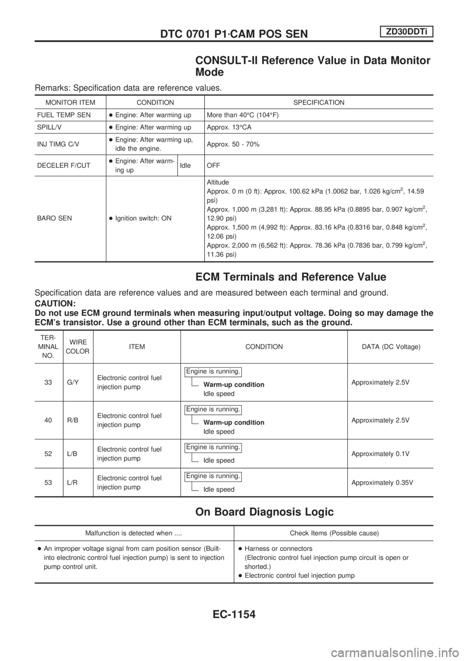
CONSULT-II Reference Value in Data Monitor
Mode
Remarks: Specification data are reference values.
MONITOR ITEM CONDITION SPECIFICATION
FUEL TEMP SEN+Engine: After warming up More than 40ÉC (104ÉF)
SPILL/V+Engine: After warming up Approx. 13ÉCA
INJ TIMG C/V+Engine: After warming up,
idle the engine.Approx. 50 - 70%
DECELER F/CUT+Engine: After warm-
ing upIdle OFF
BARO SEN+Ignition switch: ONAltitude
Approx.0m(0ft): Approx. 100.62 kPa (1.0062 bar, 1.026 kg/cm
2, 14.59
psi)
Approx. 1,000 m (3,281 ft): Approx. 88.95 kPa (0.8895 bar, 0.907 kg/cm
2,
12.90 psi)
Approx. 1,500 m (4,992 ft): Approx. 83.16 kPa (0.8316 bar, 0.848 kg/cm
2,
12.06 psi)
Approx. 2,000 m (6,562 ft): Approx. 78.36 kPa (0.7836 bar, 0.799 kg/cm
2,
11.36 psi)
ECM Terminals and Reference Value
Specification data are reference values and are measured between each terminal and ground.
CAUTION:
Do not use ECM ground terminals when measuring input/output voltage. Doing so may damage the
ECM's transistor. Use a ground other than ECM terminals, such as the ground.
TER-
MINAL
NO.WIRE
COLORITEM CONDITION DATA (DC Voltage)
33 G/YElectronic control fuel
injection pumpEngine is running.
Warm-up condition
Idle speedApproximately 2.5V
40 R/BElectronic control fuel
injection pumpEngine is running.
Warm-up condition
Idle speedApproximately 2.5V
52 L/BElectronic control fuel
injection pumpEngine is running.
Idle speedApproximately 0.1V
53 L/RElectronic control fuel
injection pumpEngine is running.
Idle speedApproximately 0.35V
On Board Diagnosis Logic
Malfunction is detected when .... Check Items (Possible cause)
+An improper voltage signal from cam position sensor (Built-
into electronic control fuel injection pump) is sent to injection
pump control unit.+Harness or connectors
(Electronic control fuel injection pump circuit is open or
shorted.)
+Electronic control fuel injection pump
DTC 0701 P1zCAM POS SENZD30DDTi
EC-1154
Page 390 of 1033
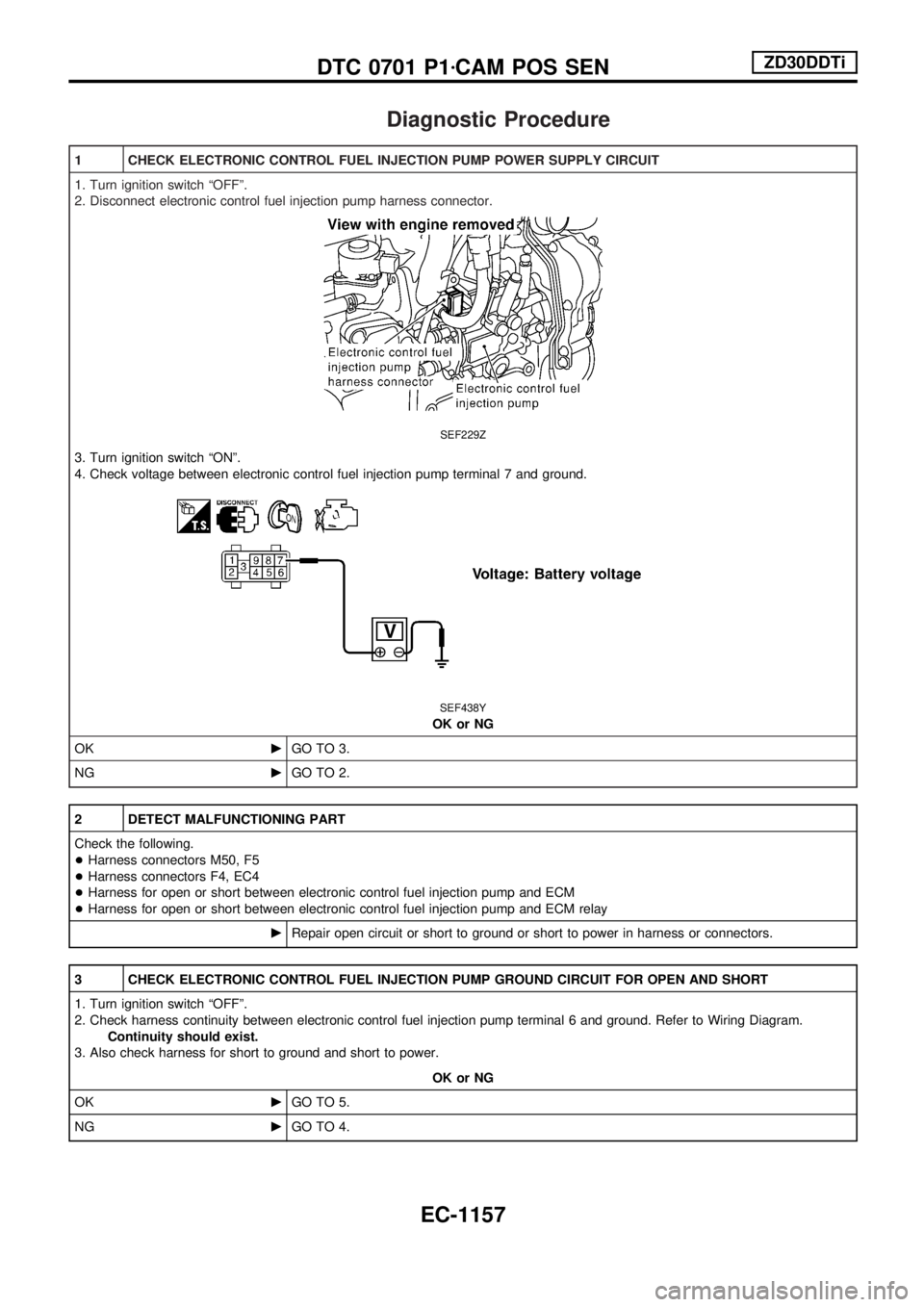
Diagnostic Procedure
1 CHECK ELECTRONIC CONTROL FUEL INJECTION PUMP POWER SUPPLY CIRCUIT
1. Turn ignition switch ªOFFº.
2. Disconnect electronic control fuel injection pump harness connector.
SEF229Z
3. Turn ignition switch ªONº.
4. Check voltage between electronic control fuel injection pump terminal 7 and ground.
SEF438Y
OK or NG
OKcGO TO 3.
NGcGO TO 2.
2 DETECT MALFUNCTIONING PART
Check the following.
+Harness connectors M50, F5
+Harness connectors F4, EC4
+Harness for open or short between electronic control fuel injection pump and ECM
+Harness for open or short between electronic control fuel injection pump and ECM relay
cRepair open circuit or short to ground or short to power in harness or connectors.
3 CHECK ELECTRONIC CONTROL FUEL INJECTION PUMP GROUND CIRCUIT FOR OPEN AND SHORT
1. Turn ignition switch ªOFFº.
2. Check harness continuity between electronic control fuel injection pump terminal 6 and ground. Refer to Wiring Diagram.
Continuity should exist.
3. Also check harness for short to ground and short to power.
OK or NG
OKcGO TO 5.
NGcGO TO 4.
DTC 0701 P1zCAM POS SENZD30DDTi
EC-1157
Page 391 of 1033
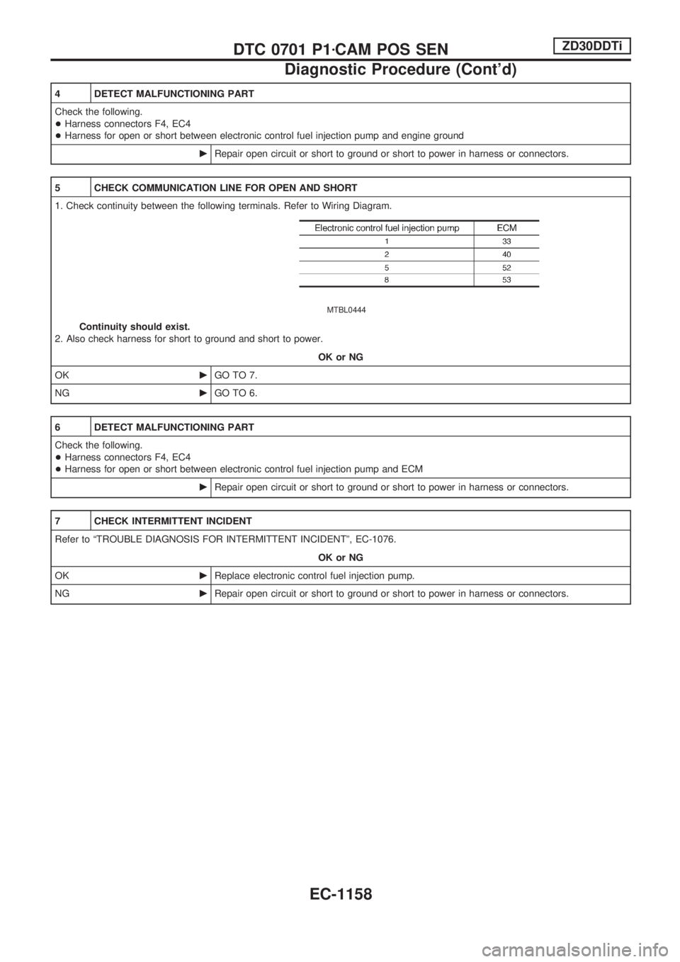
4 DETECT MALFUNCTIONING PART
Check the following.
+Harness connectors F4, EC4
+Harness for open or short between electronic control fuel injection pump and engine ground
cRepair open circuit or short to ground or short to power in harness or connectors.
5 CHECK COMMUNICATION LINE FOR OPEN AND SHORT
1. Check continuity between the following terminals. Refer to Wiring Diagram.
MTBL0444
Continuity should exist.
2. Also check harness for short to ground and short to power.
OK or NG
OKcGO TO 7.
NGcGO TO 6.
6 DETECT MALFUNCTIONING PART
Check the following.
+Harness connectors F4, EC4
+Harness for open or short between electronic control fuel injection pump and ECM
cRepair open circuit or short to ground or short to power in harness or connectors.
7 CHECK INTERMITTENT INCIDENT
Refer to ªTROUBLE DIAGNOSIS FOR INTERMITTENT INCIDENTº, EC-1076.
OK or NG
OKcReplace electronic control fuel injection pump.
NGcRepair open circuit or short to ground or short to power in harness or connectors.
DTC 0701 P1zCAM POS SENZD30DDTi
Diagnostic Procedure (Cont'd)
EC-1158
Page 393 of 1033
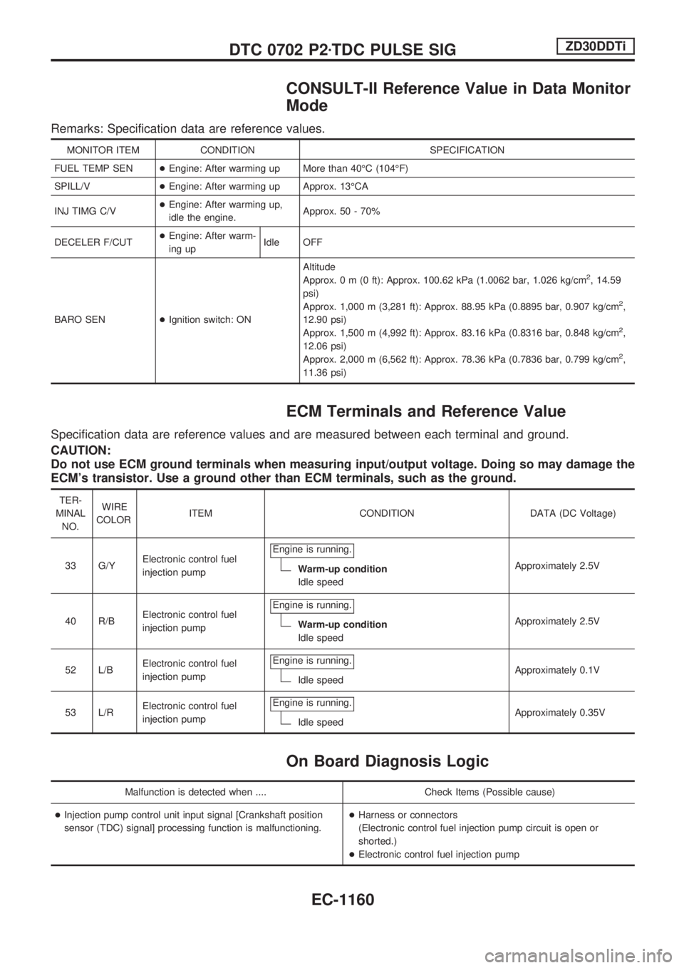
CONSULT-II Reference Value in Data Monitor
Mode
Remarks: Specification data are reference values.
MONITOR ITEM CONDITION SPECIFICATION
FUEL TEMP SEN+Engine: After warming up More than 40ÉC (104ÉF)
SPILL/V+Engine: After warming up Approx. 13ÉCA
INJ TIMG C/V+Engine: After warming up,
idle the engine.Approx. 50 - 70%
DECELER F/CUT+Engine: After warm-
ing upIdle OFF
BARO SEN+Ignition switch: ONAltitude
Approx.0m(0ft): Approx. 100.62 kPa (1.0062 bar, 1.026 kg/cm
2, 14.59
psi)
Approx. 1,000 m (3,281 ft): Approx. 88.95 kPa (0.8895 bar, 0.907 kg/cm
2,
12.90 psi)
Approx. 1,500 m (4,992 ft): Approx. 83.16 kPa (0.8316 bar, 0.848 kg/cm
2,
12.06 psi)
Approx. 2,000 m (6,562 ft): Approx. 78.36 kPa (0.7836 bar, 0.799 kg/cm
2,
11.36 psi)
ECM Terminals and Reference Value
Specification data are reference values and are measured between each terminal and ground.
CAUTION:
Do not use ECM ground terminals when measuring input/output voltage. Doing so may damage the
ECM's transistor. Use a ground other than ECM terminals, such as the ground.
TER-
MINAL
NO.WIRE
COLORITEM CONDITION DATA (DC Voltage)
33 G/YElectronic control fuel
injection pumpEngine is running.
Warm-up condition
Idle speedApproximately 2.5V
40 R/BElectronic control fuel
injection pumpEngine is running.
Warm-up condition
Idle speedApproximately 2.5V
52 L/BElectronic control fuel
injection pumpEngine is running.
Idle speedApproximately 0.1V
53 L/RElectronic control fuel
injection pumpEngine is running.
Idle speedApproximately 0.35V
On Board Diagnosis Logic
Malfunction is detected when .... Check Items (Possible cause)
+Injection pump control unit input signal [Crankshaft position
sensor (TDC) signal] processing function is malfunctioning.+Harness or connectors
(Electronic control fuel injection pump circuit is open or
shorted.)
+Electronic control fuel injection pump
DTC 0702 P2zTDC PULSE SIGZD30DDTi
EC-1160
Page 396 of 1033
Diagnostic Procedure
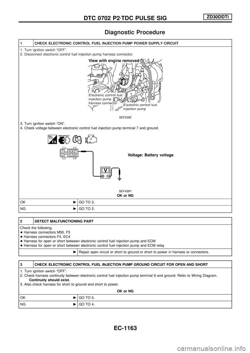
1 CHECK ELECTRONIC CONTROL FUEL INJECTION PUMP POWER SUPPLY CIRCUIT
1. Turn ignition switch ªOFFº.
2. Disconnect electronic control fuel injection pump harness connector.
SEF229Z
3. Turn ignition switch ªONº.
4. Check voltage between electronic control fuel injection pump terminal 7 and ground.
SEF438Y
OK or NG
OKcGO TO 3.
NGcGO TO 2.
2 DETECT MALFUNCTIONING PART
Check the following.
+Harness connectors M50, F5
+Harness connectors F4, EC4
+Harness for open or short between electronic control fuel injection pump and ECM
+Harness for open or short between electronic control fuel injection pump and ECM relay
cRepair open circuit or short to ground or short to power in harness or connectors.
3 CHECK ELECTRONIC CONTROL FUEL INJECTION PUMP GROUND CIRCUIT FOR OPEN AND SHORT
1. Turn ignition switch ªOFFº.
2. Check harness continuity between electronic control fuel injection pump terminal 6 and ground. Refer to Wiring Diagram.
Continuity should exist.
3. Also check harness for short to ground and short to power.
OK or NG
OKcGO TO 5.
NGcGO TO 4.
DTC 0702 P2zTDC PULSE SIGZD30DDTi
EC-1163
Page 397 of 1033
4 DETECT MALFUNCTIONING PART
Check the following.
+Harness connectors F4, EC4
+Harness for open or short between electronic control fuel injection pump and engine ground
cRepair open circuit or short to ground or short to power in harness or connectors.
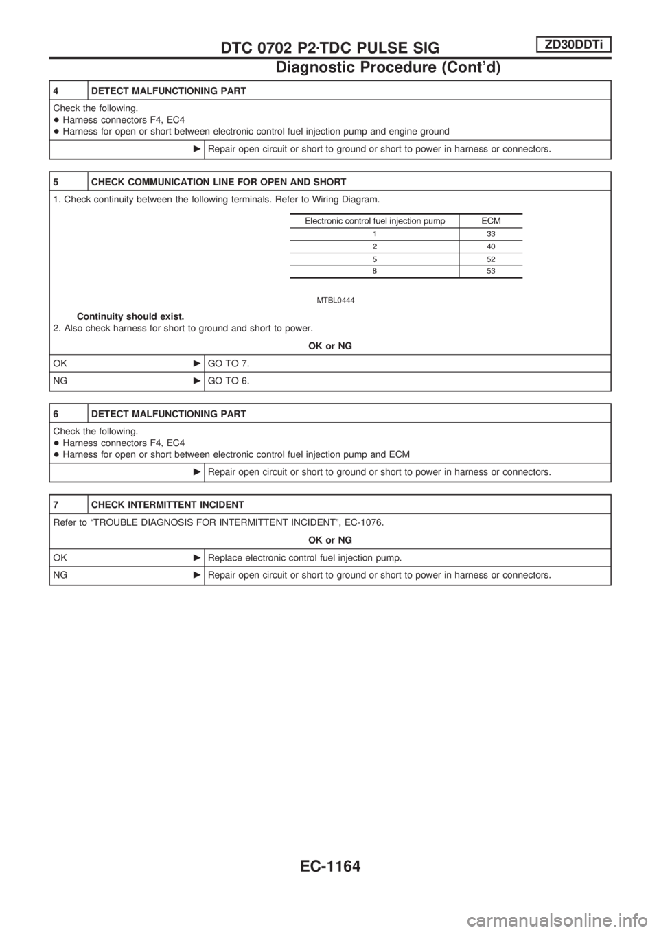
5 CHECK COMMUNICATION LINE FOR OPEN AND SHORT
1. Check continuity between the following terminals. Refer to Wiring Diagram.
MTBL0444
Continuity should exist.
2. Also check harness for short to ground and short to power.
OK or NG
OKcGO TO 7.
NGcGO TO 6.
6 DETECT MALFUNCTIONING PART
Check the following.
+Harness connectors F4, EC4
+Harness for open or short between electronic control fuel injection pump and ECM
cRepair open circuit or short to ground or short to power in harness or connectors.
7 CHECK INTERMITTENT INCIDENT
Refer to ªTROUBLE DIAGNOSIS FOR INTERMITTENT INCIDENTº, EC-1076.
OK or NG
OKcReplace electronic control fuel injection pump.
NGcRepair open circuit or short to ground or short to power in harness or connectors.
DTC 0702 P2zTDC PULSE SIGZD30DDTi
Diagnostic Procedure (Cont'd)
EC-1164