rpm NISSAN PATROL 2000 Electronic Owner's Guide
[x] Cancel search | Manufacturer: NISSAN, Model Year: 2000, Model line: PATROL, Model: NISSAN PATROL 2000Pages: 1033, PDF Size: 30.71 MB
Page 494 of 1033
Description
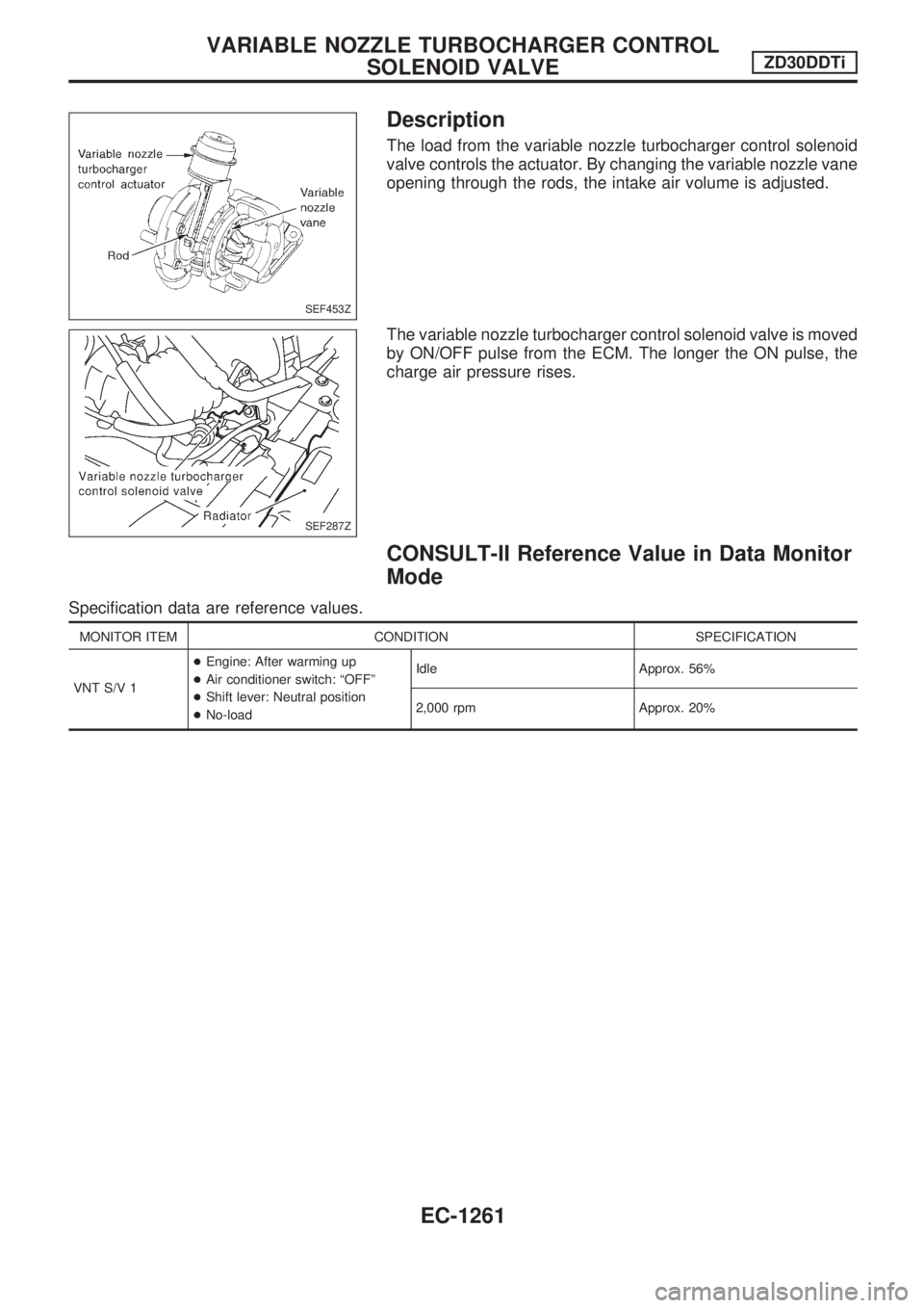
The load from the variable nozzle turbocharger control solenoid
valve controls the actuator. By changing the variable nozzle vane
opening through the rods, the intake air volume is adjusted.
The variable nozzle turbocharger control solenoid valve is moved
by ON/OFF pulse from the ECM. The longer the ON pulse, the
charge air pressure rises.
CONSULT-II Reference Value in Data Monitor
Mode
Specification data are reference values.
MONITOR ITEM CONDITION SPECIFICATION
VNT S/V 1+Engine: After warming up
+Air conditioner switch: ªOFFº
+Shift lever: Neutral position
+No-loadIdle Approx. 56%
2,000 rpm Approx. 20%
SEF453Z
SEF287Z
VARIABLE NOZZLE TURBOCHARGER CONTROL
SOLENOID VALVEZD30DDTi
EC-1261
Page 495 of 1033
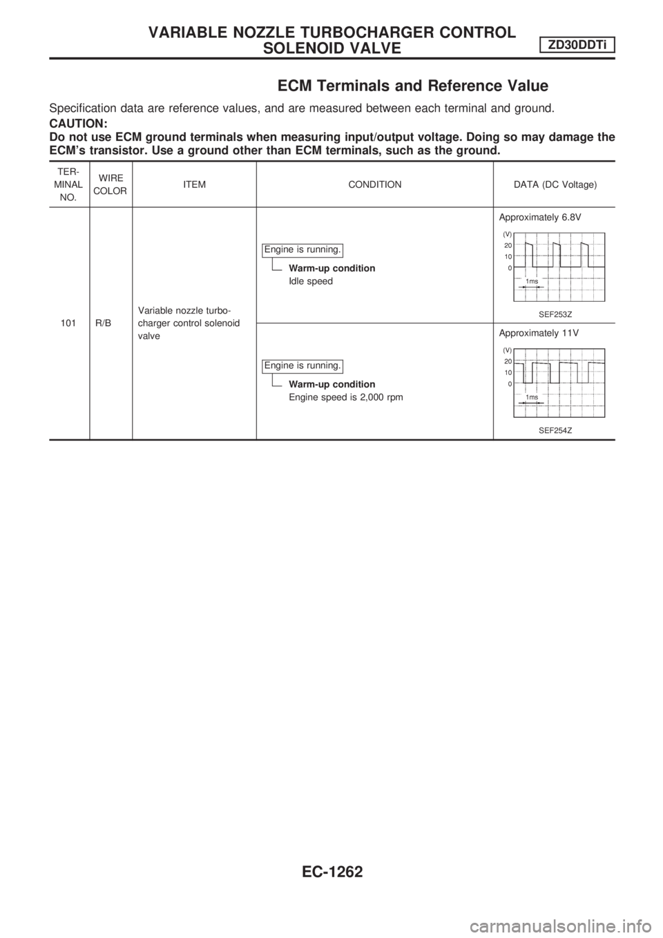
ECM Terminals and Reference Value
Specification data are reference values, and are measured between each terminal and ground.
CAUTION:
Do not use ECM ground terminals when measuring input/output voltage. Doing so may damage the
ECM's transistor. Use a ground other than ECM terminals, such as the ground.
TER-
MINAL
NO.WIRE
COLORITEM CONDITION DATA (DC Voltage)
101 R/BVariable nozzle turbo-
charger control solenoid
valveEngine is running.
Warm-up condition
Idle speedApproximately 6.8V
SEF253Z
Engine is running.
Warm-up condition
Engine speed is 2,000 rpmApproximately 11V
SEF254Z
VARIABLE NOZZLE TURBOCHARGER CONTROL
SOLENOID VALVEZD30DDTi
EC-1262
Page 497 of 1033
Diagnostic Procedure
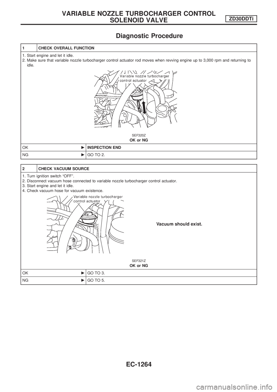
1 CHECK OVERALL FUNCTION
1. Start engine and let it idle.
2. Make sure that variable nozzle turbocharger control actuator rod moves when revving engine up to 3,000 rpm and returning to
idle.
SEF320Z
OK or NG
OKcINSPECTION END
NGcGO TO 2.
2 CHECK VACUUM SOURCE
1. Turn ignition switch ªOFFº.
2. Disconnect vacuum hose connected to variable nozzle turbocharger control actuator.
3. Start engine and let it idle.
4. Check vacuum hose for vacuum existence.
SEF321Z
OK or NG
OKcGO TO 3.
NGcGO TO 5.
VARIABLE NOZZLE TURBOCHARGER CONTROL
SOLENOID VALVEZD30DDTi
EC-1264
Page 502 of 1033
Description
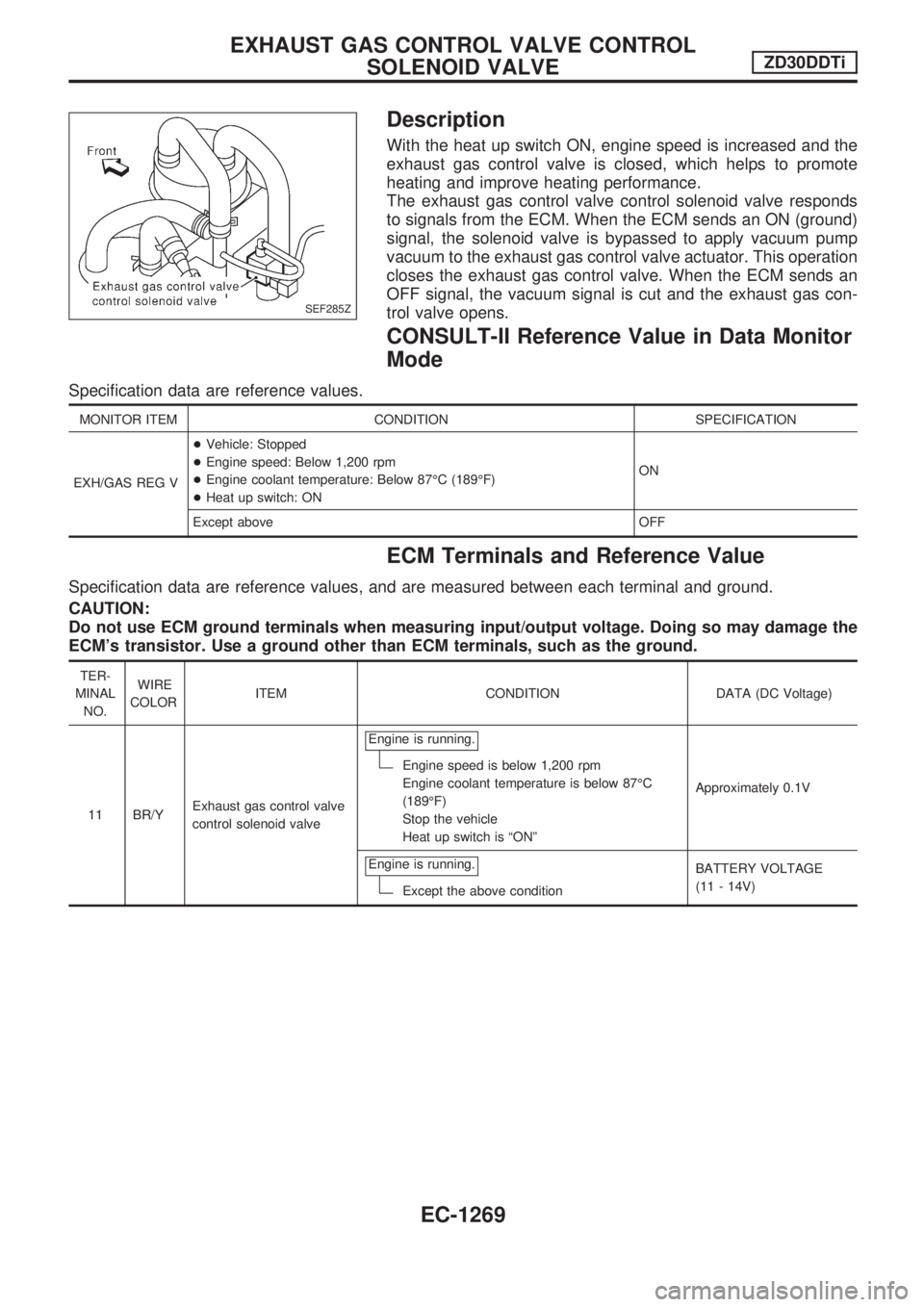
With the heat up switch ON, engine speed is increased and the
exhaust gas control valve is closed, which helps to promote
heating and improve heating performance.
The exhaust gas control valve control solenoid valve responds
to signals from the ECM. When the ECM sends an ON (ground)
signal, the solenoid valve is bypassed to apply vacuum pump
vacuum to the exhaust gas control valve actuator. This operation
closes the exhaust gas control valve. When the ECM sends an
OFF signal, the vacuum signal is cut and the exhaust gas con-
trol valve opens.
CONSULT-II Reference Value in Data Monitor
Mode
Specification data are reference values.
MONITOR ITEM CONDITION SPECIFICATION
EXH/GAS REG V+Vehicle: Stopped
+Engine speed: Below 1,200 rpm
+Engine coolant temperature: Below 87ÉC (189ÉF)
+Heat up switch: ONON
Except above OFF
ECM Terminals and Reference Value
Specification data are reference values, and are measured between each terminal and ground.
CAUTION:
Do not use ECM ground terminals when measuring input/output voltage. Doing so may damage the
ECM's transistor. Use a ground other than ECM terminals, such as the ground.
TER-
MINAL
NO.WIRE
COLORITEM CONDITION DATA (DC Voltage)
11 BR/YExhaust gas control valve
control solenoid valveEngine is running.
Engine speed is below 1,200 rpm
Engine coolant temperature is below 87ÉC
(189ÉF)
Stop the vehicle
Heat up switch is ªONºApproximately 0.1V
Engine is running.
Except the above conditionBATTERY VOLTAGE
(11 - 14V)
SEF285Z
EXHAUST GAS CONTROL VALVE CONTROL
SOLENOID VALVEZD30DDTi
EC-1269
Page 510 of 1033
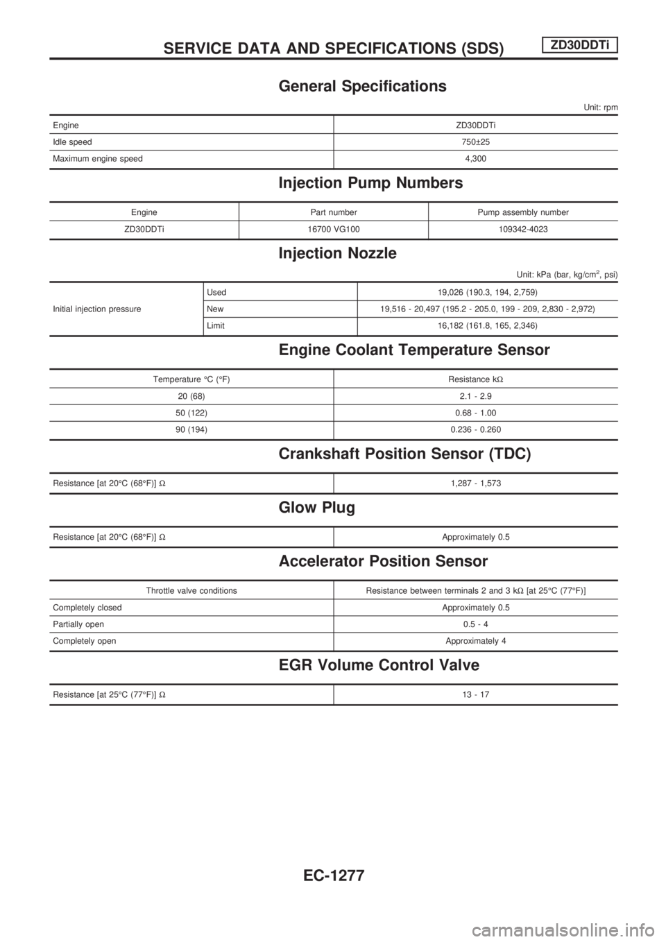
General Specifications
Unit: rpm
EngineZD30DDTi
Idle speed750 25
Maximum engine speed4,300
Injection Pump Numbers
Engine Part number Pump assembly number
ZD30DDTi 16700 VG100 109342-4023
Injection Nozzle
Unit: kPa (bar, kg/cm2, psi)
Initial injection pressureUsed 19,026 (190.3, 194, 2,759)
New 19,516 - 20,497 (195.2 - 205.0, 199 - 209, 2,830 - 2,972)
Limit 16,182 (161.8, 165, 2,346)
Engine Coolant Temperature Sensor
Temperature ÉC (ÉF) Resistance kW
20 (68) 2.1 - 2.9
50 (122) 0.68 - 1.00
90 (194) 0.236 - 0.260
Crankshaft Position Sensor (TDC)
Resistance [at 20ÉC (68ÉF)]W1,287 - 1,573
Glow Plug
Resistance [at 20ÉC (68ÉF)]WApproximately 0.5
Accelerator Position Sensor
Throttle valve conditions Resistance between terminals 2 and 3 kW[at 25ÉC (77ÉF)]
Completely closedApproximately 0.5
Partially open0.5-4
Completely openApproximately 4
EGR Volume Control Valve
Resistance [at 25ÉC (77ÉF)]W13-17
SERVICE DATA AND SPECIFICATIONS (SDS)ZD30DDTi
EC-1277
Page 549 of 1033
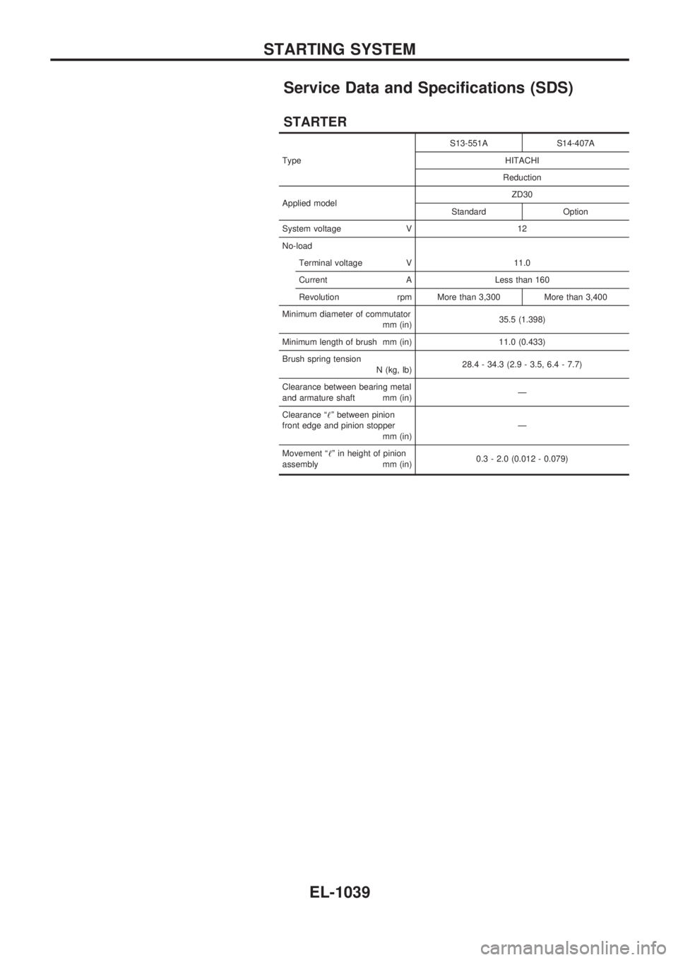
Service Data and Specifications (SDS)
STARTER
TypeS13-551A S14-407A
HITACHI
Reduction
Applied modelZD30
Standard Option
System voltage V 12
No-load
Terminal voltage V 11.0
Current A Less than 160
Revolution rpm More than 3,300 More than 3,400
Minimum diameter of commutator
mm (in)35.5 (1.398)
Minimum length of brush mm (in) 11.0 (0.433)
Brush spring tension
N (kg, lb)28.4 - 34.3 (2.9 - 3.5, 6.4 - 7.7)
Clearance between bearing metal
and armature shaft mm (in)Ð
Clearance ª!º between pinion
front edge and pinion stopper
mm (in)Ð
Movement ª!º in height of pinion
assembly mm (in)0.3 - 2.0 (0.012 - 0.079)
STARTING SYSTEM
EL-1039
Page 551 of 1033
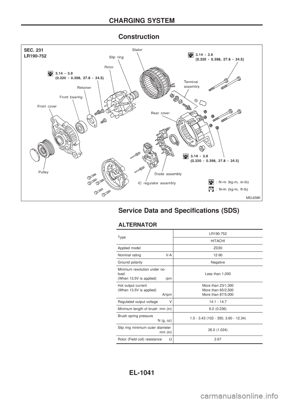
Construction
Service Data and Specifications (SDS)
ALTERNATOR
TypeLR190-752
HITACHI
Applied model ZD30
Nominal rating V-A 12-90
Ground polarity Negative
Minimum revolution under no-
load
(When 13.5V is applied) rpmLess than 1,000
Hot output current
(When 13.5V is applied)
A/rpmMore than 23/1,300
More than 65/2,500
More than 87/5,000
Regulated output voltage V 14.1 - 14.7
Minimum length of brush mm (in) 6.0 (0.236)
Brush spring pressure
N (g, oz)1.0 - 3.43 (102 - 350, 3.60 - 12.34)
Slip ring minimum outer diameter
mm (in)26.0 (1.024)
Rotor (Field coil) resistanceW2.67
MEL658K
CHARGING SYSTEM
EL-1041
Page 748 of 1033
1. Warm up engine.
2. Turn ignition switch OFF.
3.
Using CONSULT-II, make sure no error codes are indicated for
self-diagnosis items. Refer to EC section, ªFuel Pressure
Releaseº.
+Do not disconnect CONSULT-II until the end of this opera-
tion; it will be used to check engine rpm and for error detec-
tion at the end of this operation.
4. Disconnect the negative battery terminal.
5. Remove the following parts.
+Intercooler cover
+Intercooler
+Throttle body
+Rocker cover
6. To prevent fuel from being injected during inspection, remove
fuel injection pump fuse [ENG CONT (20A)] from fuse box on
the right side of engine compartment.
7. Remove glow plugs from all the cylinders.
+Before removal, clean the surrounding area to prevent
entry of any foreign materials into the engine.
+Carefully remove glow plugs to prevent any damage or
breakage.
+
Handle with care to avoid applying any shock to glow plugs.
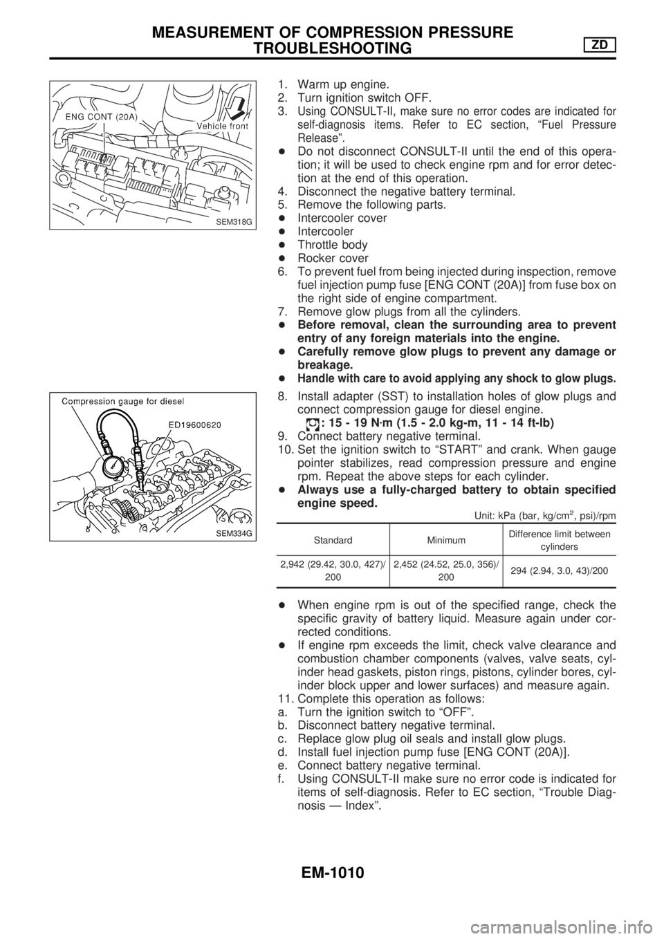
8. Install adapter (SST) to installation holes of glow plugs and
connect compression gauge for diesel engine.
:15-19Nzm (1.5 - 2.0 kg-m, 11 - 14 ft-lb)
9. Connect battery negative terminal.
10. Set the ignition switch to ªSTARTº and crank. When gauge
pointer stabilizes, read compression pressure and engine
rpm. Repeat the above steps for each cylinder.
+Always use a fully-charged battery to obtain specified
engine speed.
Unit: kPa (bar, kg/cm2, psi)/rpm
Standard MinimumDifference limit between
cylinders
2,942 (29.42, 30.0, 427)/
2002,452 (24.52, 25.0, 356)/
200294 (2.94, 3.0, 43)/200
+When engine rpm is out of the specified range, check the
specific gravity of battery liquid. Measure again under cor-
rected conditions.
+If engine rpm exceeds the limit, check valve clearance and
combustion chamber components (valves, valve seats, cyl-
inder head gaskets, piston rings, pistons, cylinder bores, cyl-
inder block upper and lower surfaces) and measure again.
11. Complete this operation as follows:
a. Turn the ignition switch to ªOFFº.
b. Disconnect battery negative terminal.
c. Replace glow plug oil seals and install glow plugs.
d. Install fuel injection pump fuse [ENG CONT (20A)].
e. Connect battery negative terminal.
f. Using CONSULT-II make sure no error code is indicated for
items of self-diagnosis. Refer to EC section, ªTrouble Diag-
nosis Ð Indexº.
SEM318G
SEM334G
MEASUREMENT OF COMPRESSION PRESSURE
TROUBLESHOOTINGZD
EM-1010
Page 823 of 1033
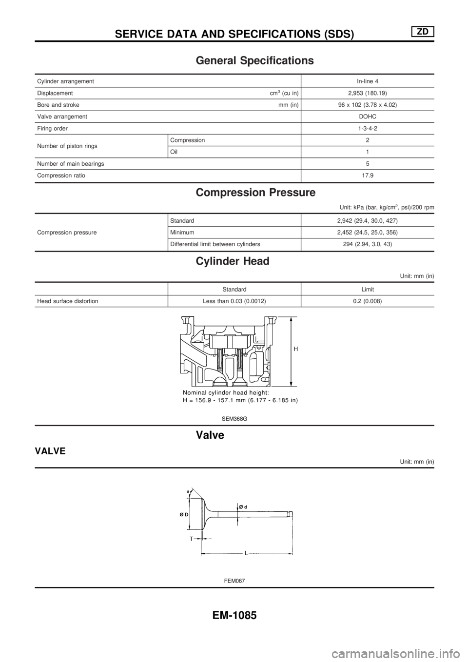
General Specifications
Cylinder arrangementIn-line 4
Displacementcm
3(cu in) 2,953 (180.19)
Bore and strokemm (in) 96 x 102 (3.78 x 4.02)
Valve arrangementDOHC
Firing order1-3-4-2
Number of piston ringsCompression 2
Oil1
Number of main bearings5
Compression ratio17.9
Compression Pressure
Unit: kPa (bar, kg/cm2, psi)/200 rpm
Compression pressureStandard 2,942 (29.4, 30.0, 427)
Minimum 2,452 (24.5, 25.0, 356)
Differential limit between cylinders 294 (2.94, 3.0, 43)
Cylinder Head
Unit: mm (in)
Standard Limit
Head surface distortion Less than 0.03 (0.0012) 0.2 (0.008)
SEM368G
Valve
VALVE
Unit: mm (in)
FEM067
SERVICE DATA AND SPECIFICATIONS (SDS)ZD
EM-1085
Page 886 of 1033
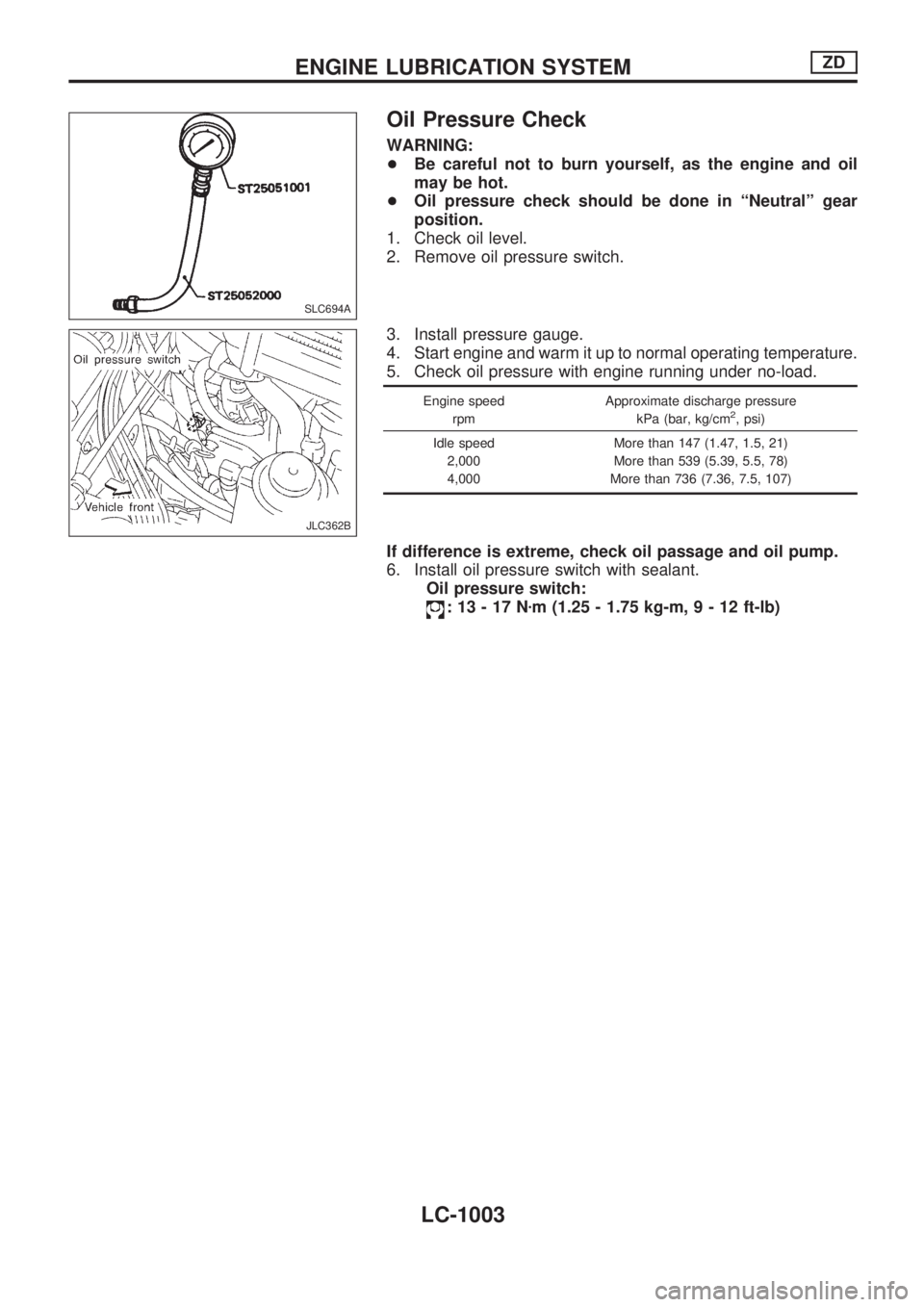
Oil Pressure Check
WARNING:
+Be careful not to burn yourself, as the engine and oil
may be hot.
+Oil pressure check should be done in ªNeutralº gear
position.
1. Check oil level.
2. Remove oil pressure switch.
3. Install pressure gauge.
4. Start engine and warm it up to normal operating temperature.
5. Check oil pressure with engine running under no-load.
Engine speed
rpmApproximate discharge pressure
kPa (bar, kg/cm2, psi)
Idle speed
2,000
4,000More than 147 (1.47, 1.5, 21)
More than 539 (5.39, 5.5, 78)
More than 736 (7.36, 7.5, 107)
If difference is extreme, check oil passage and oil pump.
6. Install oil pressure switch with sealant.
Oil pressure switch:
:13-17Nzm (1.25 - 1.75 kg-m,9-12ft-lb)
SLC694A
JLC362B
ENGINE LUBRICATION SYSTEMZD
LC-1003