rpm NISSAN PATROL 2000 Electronic Owner's Manual
[x] Cancel search | Manufacturer: NISSAN, Model Year: 2000, Model line: PATROL, Model: NISSAN PATROL 2000Pages: 1033, PDF Size: 30.71 MB
Page 349 of 1033
17 CHECK MAIN 12 CAUSES
If the cause cannot be isolated, go to ªMAIN 12 CAUSES OF OVERHEATINGº, EC-1116.
cINSPECTION END
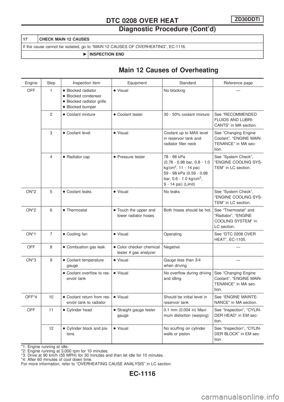
Main 12 Causes of Overheating
Engine Step Inspection item Equipment Standard Reference page
OFF 1+Blocked radiator
+Blocked condenser
+Blocked radiator grille
+Blocked bumper+Visual No blocking Ð
2+Coolant mixture+Coolant tester 30 - 50% coolant mixture See ªRECOMMENDED
FLUIDS AND LUBRI-
CANTSº in MA section.
3+Coolant level+Visual Coolant up to MAX level
in reservoir tank and
radiator filler neckSee ªChanging Engine
Coolantº, ªENGINE MAIN-
TENANCEº in MA sec-
tion.
4+Radiator cap+Pressure tester 78 - 98 kPa
(0.78 - 0.98 bar, 0.8 - 1.0
kg/cm
2, 11 - 14 psi)
59 - 98 kPa (0.59 - 0.98
bar, 0.6 - 1.0 kg/cm
2,
9 - 14 psi) (Limit)See ªSystem Checkº,
ªENGINE COOLING SYS-
TEMº in LC section.
ON*2 5+Coolant leaks+Visual No leaks See ªSystem Checkº,
ªENGINE COOLING SYS-
TEMº in LC section.
ON*2 6+Thermostat+Touch the upper and
lower radiator hosesBoth hoses should be hot. See ªThermostatº and
ªRadiatorº, ªENGINE
COOLING SYSTEMº in
LC section.
ON*1 7+Cooling fan+Visual Operating See ªDTC 0208 OVER
HEATº, EC-1105.
OFF 8+Combustion gas leak+Color checker chemical
tester 4 gas analyzerNegative Ð
ON*3 9+Coolant temperature
gauge+Visual Gauge less than 3/4
when drivingÐ
+Coolant overflow to res-
ervoir tank+Visual No overflow during driving
and idlingSee ªChanging Engine
Coolantº, ªENGINE MAIN-
TENANCEº in MA sec-
tion.
OFF*4 10+Coolant return from res-
ervoir tank to radiator+Visual Should be initial level in
reservoir tankSee ªENGINE MAINTE-
NANCEº in MA section.
OFF 11+Cylinder head+Straight gauge feeler
gauge0.1 mm (0.004 in) Maxi-
mum distortion (warping)See ªInspectionº, ªCYLIN-
DER HEADº in EM sec-
tion.
12+Cylinder block and pis-
tons+Visual No scuffing on cylinder
walls or pistonSee ªInspectionº, ªCYLIN-
DER BLOCKº in EM sec-
tion.
*1: Engine running at idle.
*2: Engine running at 3,000 rpm for 10 minutes.
*3: Drive at 90 km/h (55 MPH) for 30 minutes and then let idle for 10 minutes.
*4: After 60 minutes of cool down time.
For more information, refer to ªOVERHEATING CAUSE ANALYSISº in LC section.
DTC 0208 OVER HEATZD30DDTi
Diagnostic Procedure (Cont'd)
EC-1116
Page 371 of 1033
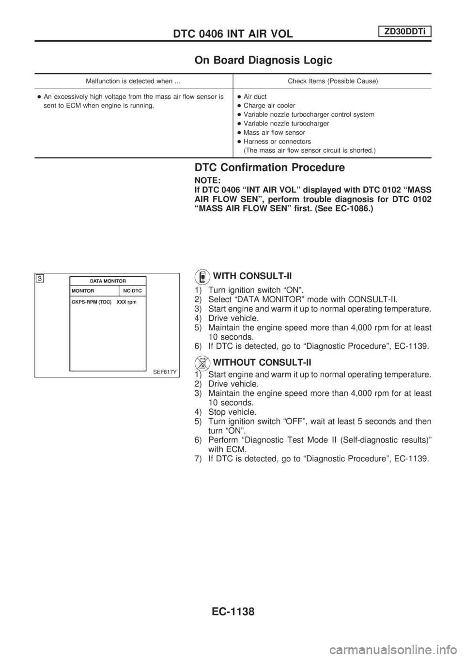
On Board Diagnosis Logic
Malfunction is detected when ... Check Items (Possible Cause)
+An excessively high voltage from the mass air flow sensor is
sent to ECM when engine is running.+Air duct
+Charge air cooler
+Variable nozzle turbocharger control system
+Variable nozzle turbocharger
+Mass air flow sensor
+Harness or connectors
(The mass air flow sensor circuit is shorted.)
DTC Confirmation Procedure
NOTE:
If DTC 0406 ªINT AIR VOLº displayed with DTC 0102 ªMASS
AIR FLOW SENº, perform trouble diagnosis for DTC 0102
ªMASS AIR FLOW SENº first. (See EC-1086.)
WITH CONSULT-II
1) Turn ignition switch ªONº.
2) Select ªDATA MONITORº mode with CONSULT-II.
3) Start engine and warm it up to normal operating temperature.
4) Drive vehicle.
5) Maintain the engine speed more than 4,000 rpm for at least
10 seconds.
6) If DTC is detected, go to ªDiagnostic Procedureº, EC-1139.
WITHOUT CONSULT-II
1) Start engine and warm it up to normal operating temperature.
2) Drive vehicle.
3) Maintain the engine speed more than 4,000 rpm for at least
10 seconds.
4) Stop vehicle.
5) Turn ignition switch ªOFFº, wait at least 5 seconds and then
turn ªONº.
6) Perform ªDiagnostic Test Mode II (Self-diagnostic results)º
with ECM.
7) If DTC is detected, go to ªDiagnostic Procedureº, EC-1139.SEF817Y
DTC 0406 INT AIR VOLZD30DDTi
EC-1138
Page 372 of 1033
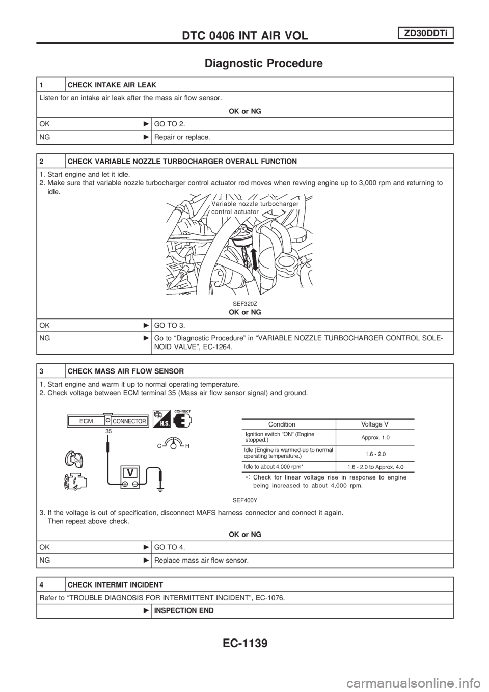
Diagnostic Procedure
1 CHECK INTAKE AIR LEAK
Listen for an intake air leak after the mass air flow sensor.
OK or NG
OKcGO TO 2.
NGcRepair or replace.
2 CHECK VARIABLE NOZZLE TURBOCHARGER OVERALL FUNCTION
1. Start engine and let it idle.
2. Make sure that variable nozzle turbocharger control actuator rod moves when revving engine up to 3,000 rpm and returning to
idle.
SEF320Z
OK or NG
OKcGO TO 3.
NGcGo to ªDiagnostic Procedureº in ªVARIABLE NOZZLE TURBOCHARGER CONTROL SOLE-
NOID VALVEº, EC-1264.
3 CHECK MASS AIR FLOW SENSOR
1. Start engine and warm it up to normal operating temperature.
2. Check voltage between ECM terminal 35 (Mass air flow sensor signal) and ground.
SEF400Y
3. If the voltage is out of specification, disconnect MAFS harness connector and connect it again.
Then repeat above check.
OK or NG
OKcGO TO 4.
NGcReplace mass air flow sensor.
4 CHECK INTERMIT INCIDENT
Refer to ªTROUBLE DIAGNOSIS FOR INTERMITTENT INCIDENTº, EC-1076.
cINSPECTION END
DTC 0406 INT AIR VOLZD30DDTi
EC-1139
Page 373 of 1033
Description
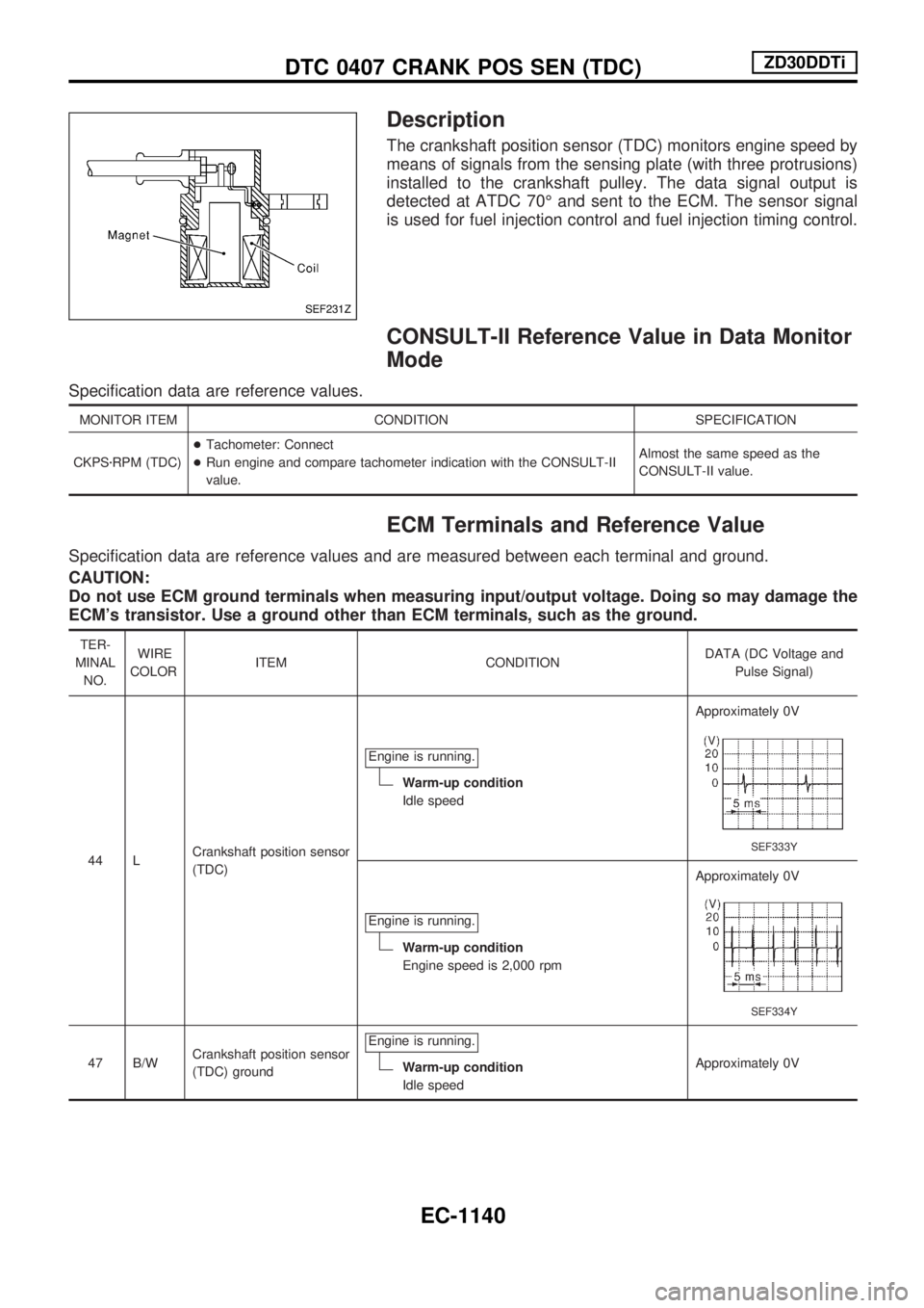
The crankshaft position sensor (TDC) monitors engine speed by
means of signals from the sensing plate (with three protrusions)
installed to the crankshaft pulley. The data signal output is
detected at ATDC 70É and sent to the ECM. The sensor signal
is used for fuel injection control and fuel injection timing control.
CONSULT-II Reference Value in Data Monitor
Mode
Specification data are reference values.
MONITOR ITEM CONDITION SPECIFICATION
CKPSzRPM (TDC)+Tachometer: Connect
+Run engine and compare tachometer indication with the CONSULT-II
value.Almost the same speed as the
CONSULT-II value.
ECM Terminals and Reference Value
Specification data are reference values and are measured between each terminal and ground.
CAUTION:
Do not use ECM ground terminals when measuring input/output voltage. Doing so may damage the
ECM's transistor. Use a ground other than ECM terminals, such as the ground.
TER-
MINAL
NO.WIRE
COLORITEM CONDITIONDATA (DC Voltage and
Pulse Signal)
44 LCrankshaft position sensor
(TDC)Engine is running.
Warm-up condition
Idle speedApproximately 0V
SEF333Y
Engine is running.
Warm-up condition
Engine speed is 2,000 rpmApproximately 0V
SEF334Y
47 B/WCrankshaft position sensor
(TDC) groundEngine is running.Warm-up condition
Idle speedApproximately 0V
SEF231Z
DTC 0407 CRANK POS SEN (TDC)ZD30DDTi
EC-1140
Page 381 of 1033
System Description
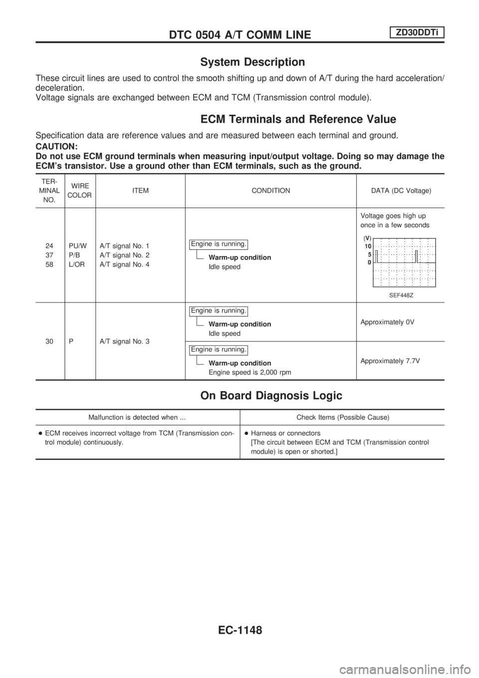
These circuit lines are used to control the smooth shifting up and down of A/T during the hard acceleration/
deceleration.
Voltage signals are exchanged between ECM and TCM (Transmission control module).
ECM Terminals and Reference Value
Specification data are reference values and are measured between each terminal and ground.
CAUTION:
Do not use ECM ground terminals when measuring input/output voltage. Doing so may damage the
ECM's transistor. Use a ground other than ECM terminals, such as the ground.
TER-
MINAL
NO.WIRE
COLORITEM CONDITION DATA (DC Voltage)
24
37
58PU/W
P/B
L/ORA/T signal No. 1
A/T signal No. 2
A/T signal No. 4Engine is running.
Warm-up condition
Idle speedVoltage goes high up
once in a few seconds
SEF448Z
30 P A/T signal No. 3Engine is running.
Warm-up condition
Idle speedApproximately 0V
Engine is running.
Warm-up condition
Engine speed is 2,000 rpmApproximately 7.7V
On Board Diagnosis Logic
Malfunction is detected when ... Check Items (Possible Cause)
+ECM receives incorrect voltage from TCM (Transmission con-
trol module) continuously.+Harness or connectors
[The circuit between ECM and TCM (Transmission control
module) is open or shorted.]
DTC 0504 A/T COMM LINEZD30DDTi
EC-1148
Page 415 of 1033
DTC Confirmation Procedure
WITH CONSULT-II
1) Turn ignition switch ªONº and wait at least 2 seconds.
2) Select ªDATA MONITORº mode with CONSULT-II.
3) Start engine and run it for at least 2 seconds at idle speed.
(If engine does not run, turn ignition switch to ªSTARTº for at
least 2 seconds.)
4) Keep engine speed at more than 2,000 rpm for at least 10
seconds.
5) If DTC is detected, go to ªDiagnostic Procedureº, EC-1184.
WITHOUT CONSULT-II
1) Turn ignition switch ªONº and wait at least 2 seconds.
2) Start engine and run it for at least 2 seconds at idle speed.
(If engine does not run, turn ignition switch to ªSTARTº for at
least 2 seconds.)
3) Keep engine speed at more than 2,000 rpm for at least 10
seconds.
4) Turn ignition switch ªOFFº, wait at least 5 seconds and then
turn ªONº.
5) Perform ªDiagnostic Test Mode II (Self-diagnostic results)º
with ECM.
6) If DTC is detected, go to ªDiagnostic Procedureº, EC-1184.
SEF817Y
DTC 0707 P7zF/INJ TIMG FBZD30DDTi
EC-1182
Page 441 of 1033
COMPONENT DESCRIPTION
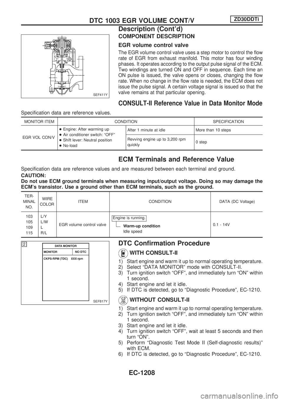
EGR volume control valve
The EGR volume control valve uses a step motor to control the flow
rate of EGR from exhaust manifold. This motor has four winding
phases. It operates according to the output pulse signal of the ECM.
Two windings are turned ON and OFF in sequence. Each time an
ON pulse is issued, the valve opens or closes, changing the flow
rate. When no change in the flow rate is needed, the ECM does not
issue the pulse signal. A certain voltage signal is issued so that the
valve remains at that particular opening.
CONSULT-II Reference Value in Data Monitor Mode
Specification data are reference values.
MONITOR ITEM CONDITION SPECIFICATION
EGR VOL CON/V+Engine: After warming up
+Air conditioner switch: ªOFFº
+Shift lever: Neutral position
+No-loadAfter 1 minute at idle More than 10 steps
Revving engine up to 3,200 rpm
quickly0 step
ECM Terminals and Reference Value
Specification data are reference values and are measured between each terminal and ground.
CAUTION:
Do not use ECM ground terminals when measuring input/output voltage. Doing so may damage the
ECM's transistor. Use a ground other than ECM terminals, such as the ground.
TER-
MINAL
NO.WIRE
COLORITEM CONDITION DATA (DC Voltage)
103
105
109
115L/Y
L/W
L
R/LEGR volume control valveEngine is running.
Warm-up condition
Idle speed0.1 - 14V
DTC Confirmation Procedure
WITH CONSULT-II
1) Start engine and warm it up to normal operating temperature.
2) Select ªDATA MONITORº mode with CONSULT-II.
3) Turn ignition switch ªOFFº, and immediately turn ªONº within
1 second.
4) Start engine and let it idle.
5) If DTC is detected, go to ªDiagnostic Procedureº, EC-1210.
WITHOUT CONSULT-II
1) Start engine and warm it up to normal operating temperature.
2) Turn ignition switch ªOFFº, and immediately turn ªONº within
1 second.
3) Start engine and let it idle.
4) Turn ignition switch ªOFFº, wait at least 5 seconds and then
turn ªONº.
5) Perform ªDiagnostic Test Mode II (Self-diagnostic results)º
with ECM.
6) If DTC is detected, go to ªDiagnostic Procedureº, EC-1210.
SEF411Y
SEF817Y
DTC 1003 EGR VOLUME CONT/VZD30DDTi
Description (Cont'd)
EC-1208
Page 454 of 1033
Description
SYSTEM DESCRIPTION
Sensor Input Signal to ECMECM
FunctionActuator
Crankshaft position
sensor (TDC)Engine speed
Glow
controlGlow lamp,
Glow relay
¯
Glow plugs Engine coolant tem-
perature sensorEngine coolant tem-
perature
When engine coolant temperature is more than approximately
75ÉC (167ÉF), the glow relay turns off, inactivating the quick-glow
control until coolant temperature drops below approximately
55ÉC (131ÉF).
When coolant temperature is lower than approximately 75ÉC
(167ÉF):
+Ignition switch ON
After ignition switch has turned to ON, the glow relay turns
ON for a certain period of time in relation to engine coolant
temperature, allowing current to flow through glow plug.
+Cranking
The glow relay turns ON, allowing current to flow through
glow plug.
+Starting
After engine has started, current continues to flow through
glow plug (after-glow mode) for a certain period in relation to
engine coolant temperature.
When engine speed exceeds approximately 4,800 rpm, cur-
rent flow through glow plug is interrupted.
The glow indicator lamp turns ON for a certain period of time in
relation to engine coolant temperature at the time glow relay is
turned ON.
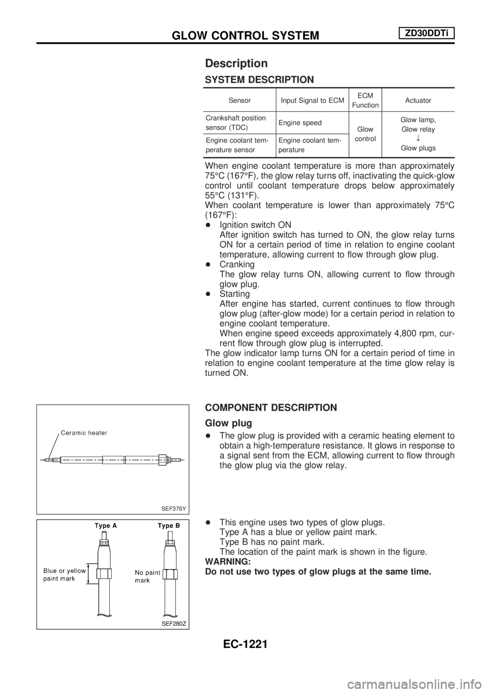
COMPONENT DESCRIPTION
Glow plug
+The glow plug is provided with a ceramic heating element to
obtain a high-temperature resistance. It glows in response to
a signal sent from the ECM, allowing current to flow through
the glow plug via the glow relay.
+This engine uses two types of glow plugs.
Type A has a blue or yellow paint mark.
Type B has no paint mark.
The location of the paint mark is shown in the figure.
WARNING:
Do not use two types of glow plugs at the same time.
SEF376Y
SEF280Z
GLOW CONTROL SYSTEMZD30DDTi
EC-1221
Page 474 of 1033
Component Description
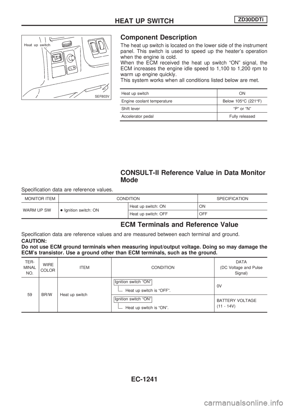
The heat up switch is located on the lower side of the instrument
panel. This switch is used to speed up the heater's operation
when the engine is cold.
When the ECM received the heat up switch ªONº signal, the
ECM increases the engine idle speed to 1,100 to 1,200 rpm to
warm up engine quickly.
This system works when all conditions listed below are met.
Heat up switch ON
Engine coolant temperature Below 105ÉC (221ÉF)
Shift lever ªPº or ªNº
Accelerator pedal Fully released
CONSULT-II Reference Value in Data Monitor
Mode
Specification data are reference values.
MONITOR ITEM CONDITION SPECIFICATION
WARM UP SW+Ignition switch: ONHeat up switch: ON ON
Heat up switch: OFF OFF
ECM Terminals and Reference Value
Specification data are reference values and are measured between each terminal and ground.
CAUTION:
Do not use ECM ground terminals when measuring input/output voltage. Doing so may damage the
ECM's transistor. Use a ground other than ECM terminals, such as the ground.
TER-
MINAL
NO.WIRE
COLORITEM CONDITIONDATA
(DC Voltage and Pulse
Signal)
59 BR/W Heat up switchIgnition switch ªONº
Heat up switch is ªOFFº.0V
Ignition switch ªONº
Heat up switch is ªONº.BATTERY VOLTAGE
(11 - 14V)
SEF803V
HEAT UP SWITCHZD30DDTi
EC-1241
Page 479 of 1033
Description
SYSTEM DESCRIPTION
Sensor Input Signal to ECMECM
FunctionActuator
Ignition switch Start signal
Swirl
control
valve
controlSwirl control valve control solenoid valve
¯Vacuum signal
Swirl control valve actuator
¯Swirl control valve Crankshaft position sensor (TDC) Engine speed
PNP switch Park/Neutral position signal
Engine coolant temperature sensor Engine coolant temperature
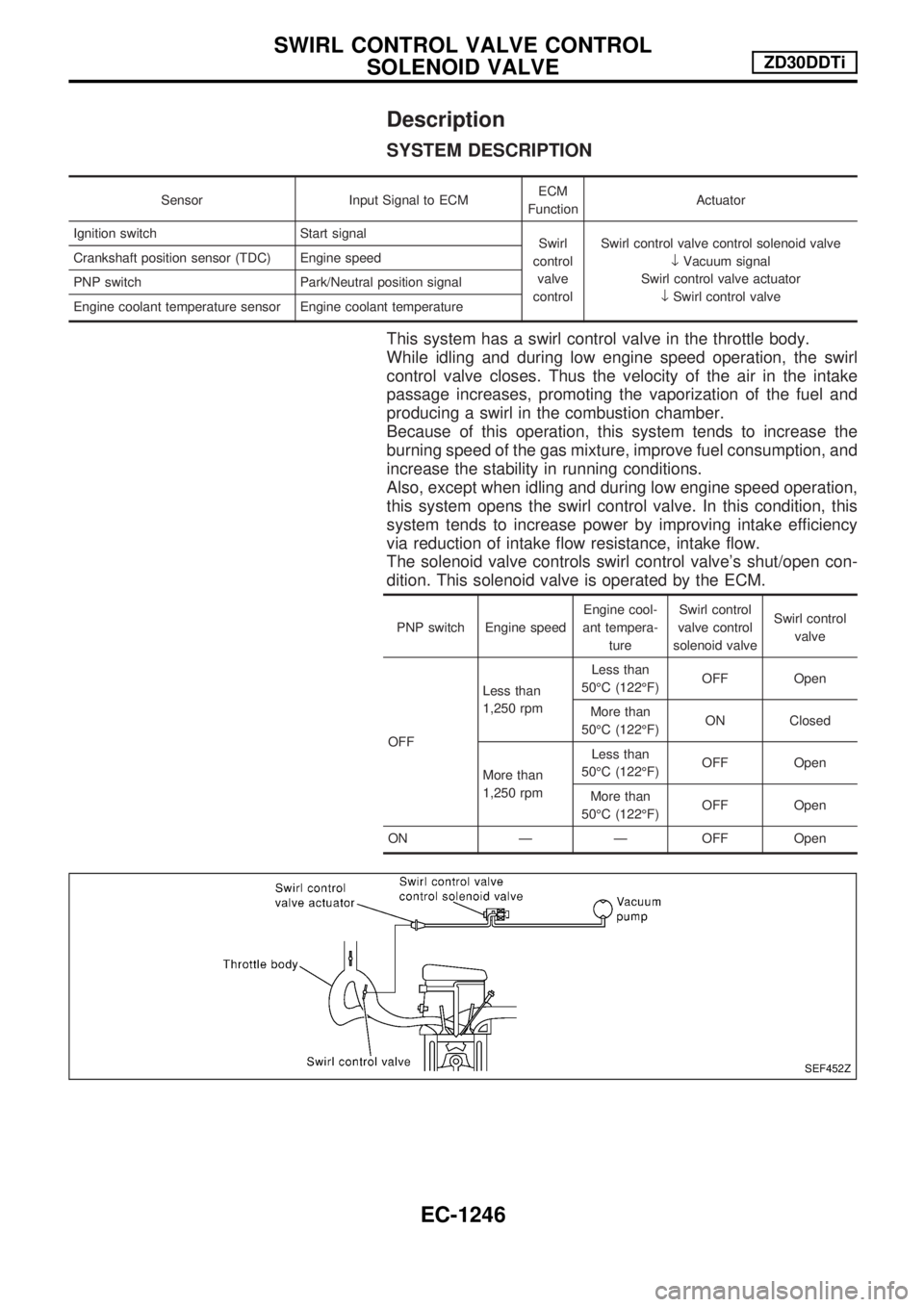
This system has a swirl control valve in the throttle body.
While idling and during low engine speed operation, the swirl
control valve closes. Thus the velocity of the air in the intake
passage increases, promoting the vaporization of the fuel and
producing a swirl in the combustion chamber.
Because of this operation, this system tends to increase the
burning speed of the gas mixture, improve fuel consumption, and
increase the stability in running conditions.
Also, except when idling and during low engine speed operation,
this system opens the swirl control valve. In this condition, this
system tends to increase power by improving intake efficiency
via reduction of intake flow resistance, intake flow.
The solenoid valve controls swirl control valve's shut/open con-
dition. This solenoid valve is operated by the ECM.
PNP switch Engine speedEngine cool-
ant tempera-
tureSwirl control
valve control
solenoid valveSwirl control
valve
OFFLess than
1,250 rpmLess than
50ÉC (122ÉF)OFF Open
More than
50ÉC (122ÉF)ON Closed
More than
1,250 rpmLess than
50ÉC (122ÉF)OFF Open
More than
50ÉC (122ÉF)OFF Open
ON Ð Ð OFF Open
SEF452Z
SWIRL CONTROL VALVE CONTROL
SOLENOID VALVEZD30DDTi
EC-1246