Harness NISSAN PATROL 2000 Electronic Service Manual
[x] Cancel search | Manufacturer: NISSAN, Model Year: 2000, Model line: PATROL, Model: NISSAN PATROL 2000Pages: 1033, PDF Size: 30.71 MB
Page 117 of 1033
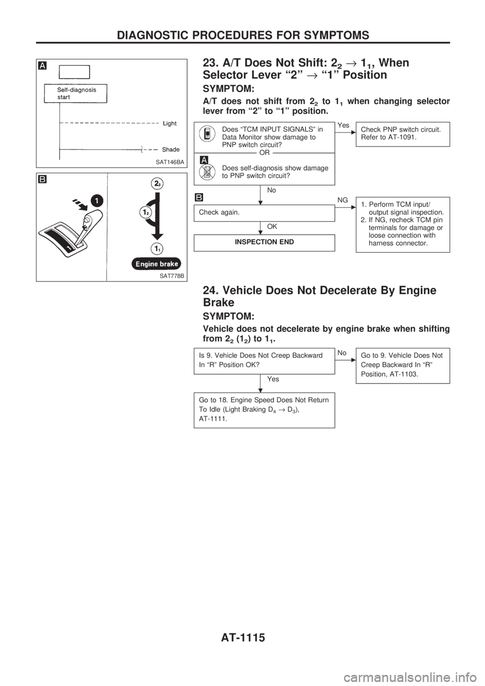
23. A/T Does Not Shift: 22®11, When
Selector Lever ª2º®ª1º Position
SYMPTOM:
A/T does not shift from 22to 11when changing selector
lever from ª2º to ª1º position.
Does ªTCM INPUT SIGNALSº in
Data Monitor show damage to
PNP switch circuit?
------------------------------------------------------------------------------------------------------------------------------------OR------------------------------------------------------------------------------------------------------------------------------------
Does self-diagnosis show damage
to PNP switch circuit?
No
cYes
Check PNP switch circuit.
Refer to AT-1091.
Check again.
OK
cNG
1. Perform TCM input/
output signal inspection.
2. If NG, recheck TCM pin
terminals for damage or
loose connection with
harness connector.
INSPECTION END
24. Vehicle Does Not Decelerate By Engine
Brake
SYMPTOM:
Vehicle does not decelerate by engine brake when shifting
from 2
2(12)to11.
Is 9. Vehicle Does Not Creep Backward
In ªRº Position OK?
Yes
cNo
Go to 9. Vehicle Does Not
Creep Backward In ªRº
Position, AT-1103.
Go to 18. Engine Speed Does Not Return
To Idle (Light Braking D
4®D3),
AT-1111.
SAT146BA
SAT778B
.
.
.
DIAGNOSTIC PROCEDURES FOR SYMPTOMS
AT-1115
Page 120 of 1033
Diagnostic Procedure
SYMPTOM 1:
+Selector lever cannot be moved from ªPº position with
key in ªONº position and brake pedal applied.
+Selector lever can be moved from ªPº position with key
in ªONº position and brake pedal released.
+Selector lever can be moved from ªPº position when key
is removed from key cylinder.
SYMPTOM 2:
Ignition key cannot be removed when selector lever is set to
ªPº position. It can be removed when selector lever is set to
any position except ªPº.
Check key interlock cable for damage.
OK
cNG
Repair key interlock cable.
Refer to ªKey Interlock
Cableº, AT-1121.
Check selector lever position for damage.
OK
cNG
Check selector lever.
Refer to ªON-VEHICLE
SERVICE Ð PNP Switch
and Manual Control Link-
age Adjustmentº.
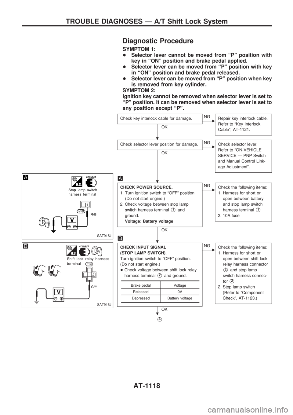
CHECK POWER SOURCE.
1. Turn ignition switch to ªOFFº position.
(Do not start engine.)
2. Check voltage between stop lamp
switch harness terminal
V1and
ground.
Voltage: Battery voltage
OK
cNG
Check the following items:
1. Harness for short or
open between battery
and stop lamp switch
harness terminal
V1
2. 10A fuse
CHECK INPUT SIGNAL
(STOP LAMP SWITCH).
Turn ignition switch to ªOFFº position.
(Do not start engine.)
+Check voltage between shift lock relay
harness terminal
V2and ground.
OK
cNG
Check the following items:
1. Harness for short or
open between shift lock
relay harness connector
V2and stop lamp
switch harness connec-
tor
V2
2. Stop lamp switch
(Refer to ªComponent
Checkº, AT-1123.)
VA
Brake pedal Voltage
Released 0V
Depressed Battery voltage
SAT915J
SAT916J
.
.
.
.
TROUBLE DIAGNOSES Ð A/T Shift Lock System
AT-1118
Page 121 of 1033
VA
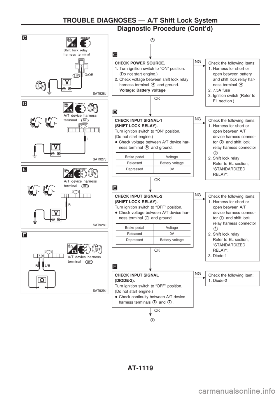
CHECK POWER SOURCE.
1. Turn ignition switch to ªONº position.
(Do not start engine.)
2. Check voltage between shift lock relay
harness terminal
V4and ground.
Voltage: Battery voltage
OK
cNG
Check the following items:
1. Harness for short or
open between battery
and shift lock relay har-
ness terminal
V4
2. 7.5A fuse
3. Ignition switch (Refer to
EL section.)
CHECK INPUT SIGNAL-1
(SHIFT LOCK RELAY).
Turn ignition switch to ªONº position.
(Do not start engine.)
+Check voltage between A/T device har-
ness terminal
V5and ground.
OK
cNG
Check the following items:
1. Harness for short or
open between A/T
device harness connec-
tor
V5and shift lock
relay harness connector
V3
2. Shift lock relay
Refer to EL section,
ªSTANDARDIZED
RELAYº.
CHECK INPUT SIGNAL-2
(SHIFT LOCK RELAY).
Turn ignition switch to ªOFFº position.
+Check voltage between A/T device har-
ness terminal
V7and ground.
OK
cNG
Check the following items:
1. Harness for short or
open between A/T
device harness connec-
tor
V7and shift lock
relay harness connector
V1
2. Shift lock relay
Refer to EL section,
ªSTANDARDIZED
RELAYº.
3. Diode-1
CHECK INPUT SIGNAL
(DIODE-2).
Turn ignition switch to ªOFFº position.
(Do not start engine.)
+Check continuity between A/T device
harness terminals
V6andV7.
OK
cNG
Check the following item:
1. Diode-2
VB
Brake pedal Voltage
Released Battery voltage
Depressed 0V
Brake pedal Voltage
Released 0V
Depressed Battery voltage
SAT926J
SAT927J
SAT928J
SAT929J
.
.
.
.
.
TROUBLE DIAGNOSES Ð A/T Shift Lock System
Diagnostic Procedure (Cont'd)
AT-1119
Page 122 of 1033
VB
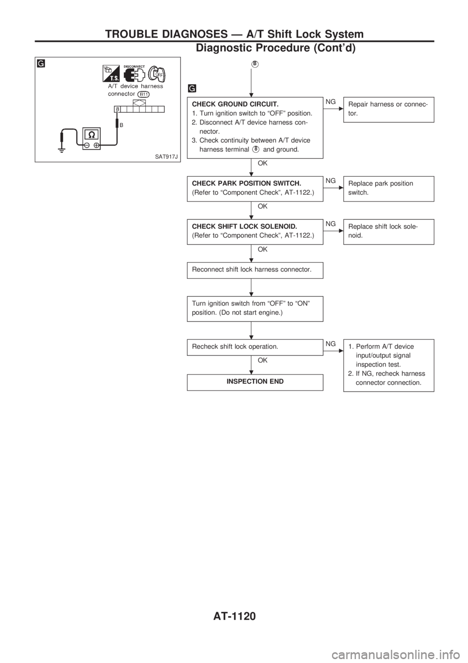
CHECK GROUND CIRCUIT.
1. Turn ignition switch to ªOFFº position.
2. Disconnect A/T device harness con-
nector.
3. Check continuity between A/T device
harness terminal
V8and ground.
OK
cNG
Repair harness or connec-
tor.
CHECK PARK POSITION SWITCH.
(Refer to ªComponent Checkº, AT-1122.)
OK
cNG
Replace park position
switch.
CHECK SHIFT LOCK SOLENOID.
(Refer to ªComponent Checkº, AT-1122.)
OK
cNG
Replace shift lock sole-
noid.
Reconnect shift lock harness connector.
Turn ignition switch from ªOFFº to ªONº
position. (Do not start engine.)
Recheck shift lock operation.
OK
cNG
1. Perform A/T device
input/output signal
inspection test.
2. If NG, recheck harness
connector connection.
INSPECTION END
SAT917J
.
.
.
.
.
.
.
TROUBLE DIAGNOSES Ð A/T Shift Lock System
Diagnostic Procedure (Cont'd)
AT-1120
Page 124 of 1033
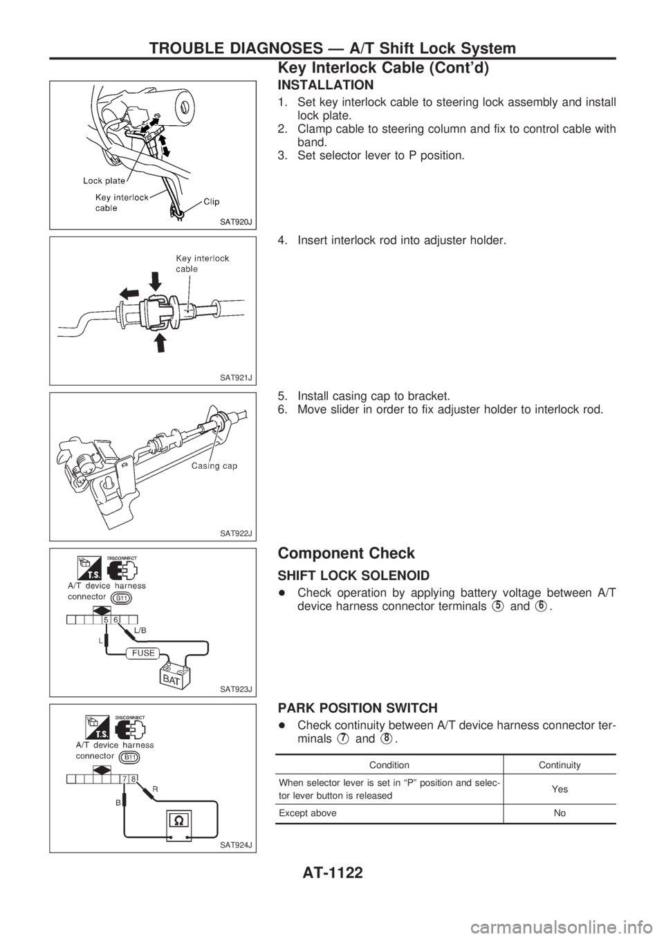
INSTALLATION
1. Set key interlock cable to steering lock assembly and install
lock plate.
2. Clamp cable to steering column and fix to control cable with
band.
3. Set selector lever to P position.
4. Insert interlock rod into adjuster holder.
5. Install casing cap to bracket.
6. Move slider in order to fix adjuster holder to interlock rod.
Component Check
SHIFT LOCK SOLENOID
+Check operation by applying battery voltage between A/T
device harness connector terminals
V5andV6.
PARK POSITION SWITCH
+Check continuity between A/T device harness connector ter-
minals
V7andV8.
Condition Continuity
When selector lever is set in ªPº position and selec-
tor lever button is releasedYes
Except above No
SAT920J
SAT921J
SAT922J
SAT923J
SAT924J
TROUBLE DIAGNOSES Ð A/T Shift Lock System
Key Interlock Cable (Cont'd)
AT-1122
Page 125 of 1033

STOP LAMP SWITCH
+Check continuity between stop lamp switch harness connec-
tor terminals
V1andV2.
Condition Continuity
When brake pedal is released No
When brake pedal is depressed Yes
Check stop lamp switch after adjusting brake pedal Ð refer
to BR section.
SAT925J
TROUBLE DIAGNOSES Ð A/T Shift Lock System
Component Check (Cont'd)
AT-1123
Page 126 of 1033
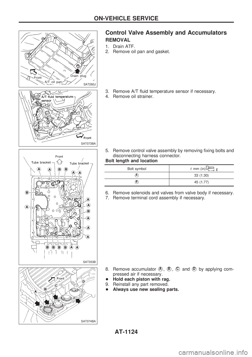
Control Valve Assembly and Accumulators
REMOVAL
1. Drain ATF.
2. Remove oil pan and gasket.
3. Remove A/T fluid temperature sensor if necessary.
4. Remove oil strainer.
5. Remove control valve assembly by removing fixing bolts and
disconnecting harness connector.
Bolt length and location
Bolt symbol!mm (in)
VA33 (1.30)
VB45 (1.77)
6. Remove solenoids and valves from valve body if necessary.
7. Remove terminal cord assembly if necessary.
8. Remove accumulator
VA,VB,VCandVDby applying com-
pressed air if necessary.
+Hold each piston with rag.
9. Reinstall any part removed.
+Always use new sealing parts.
SAT260J
SAT073BA
SAT353B
SAT074BA
ON-VEHICLE SERVICE
AT-1124
Page 129 of 1033
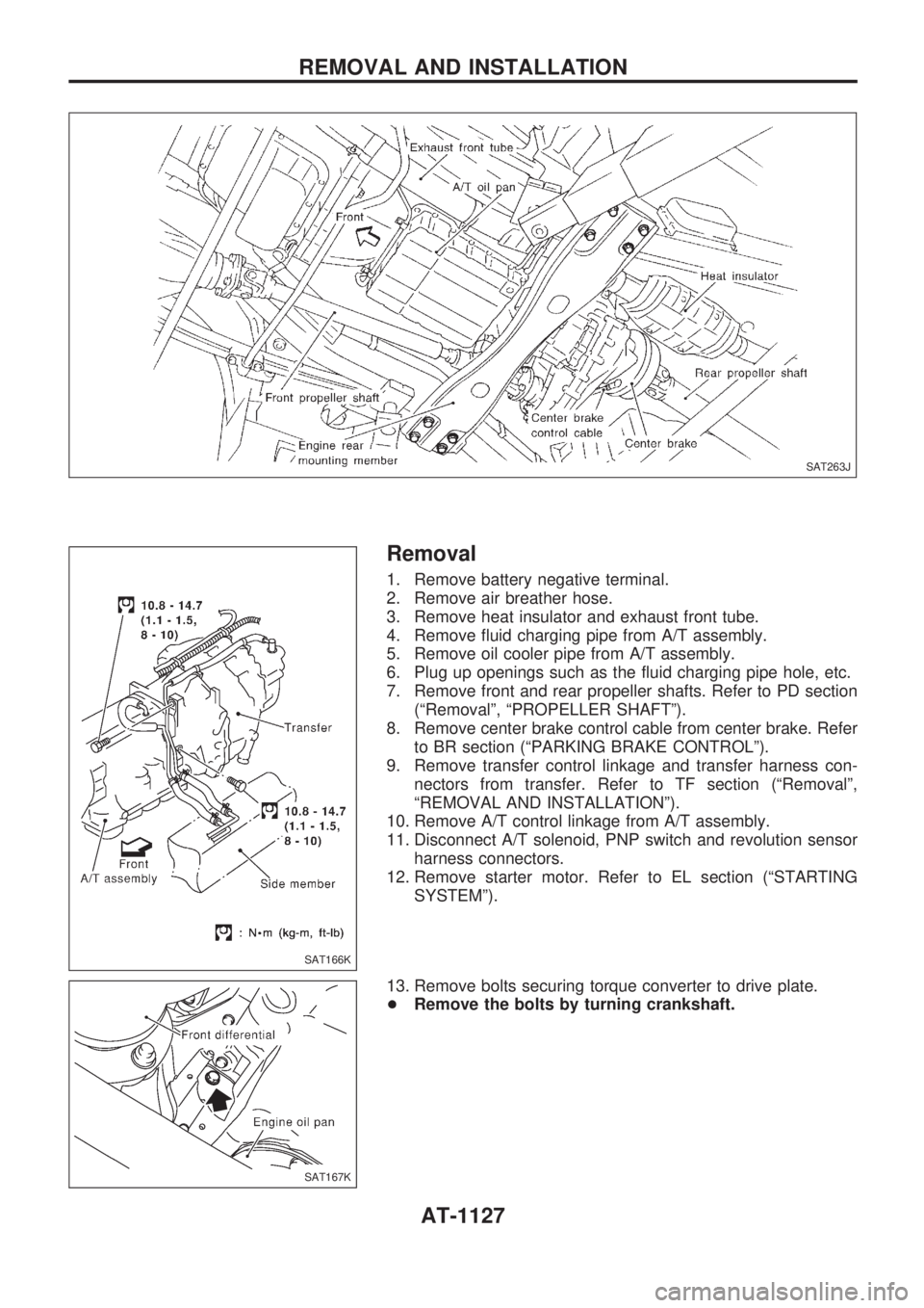
Removal
1. Remove battery negative terminal.
2. Remove air breather hose.
3. Remove heat insulator and exhaust front tube.
4. Remove fluid charging pipe from A/T assembly.
5. Remove oil cooler pipe from A/T assembly.
6. Plug up openings such as the fluid charging pipe hole, etc.
7. Remove front and rear propeller shafts. Refer to PD section
(ªRemovalº, ªPROPELLER SHAFTº).
8. Remove center brake control cable from center brake. Refer
to BR section (ªPARKING BRAKE CONTROLº).
9. Remove transfer control linkage and transfer harness con-
nectors from transfer. Refer to TF section (ªRemovalº,
ªREMOVAL AND INSTALLATIONº).
10. Remove A/T control linkage from A/T assembly.
11. Disconnect A/T solenoid, PNP switch and revolution sensor
harness connectors.
12. Remove starter motor. Refer to EL section (ªSTARTING
SYSTEMº).
13. Remove bolts securing torque converter to drive plate.
+Remove the bolts by turning crankshaft.
SAT263J
SAT166K
SAT167K
REMOVAL AND INSTALLATION
AT-1127
Page 204 of 1033
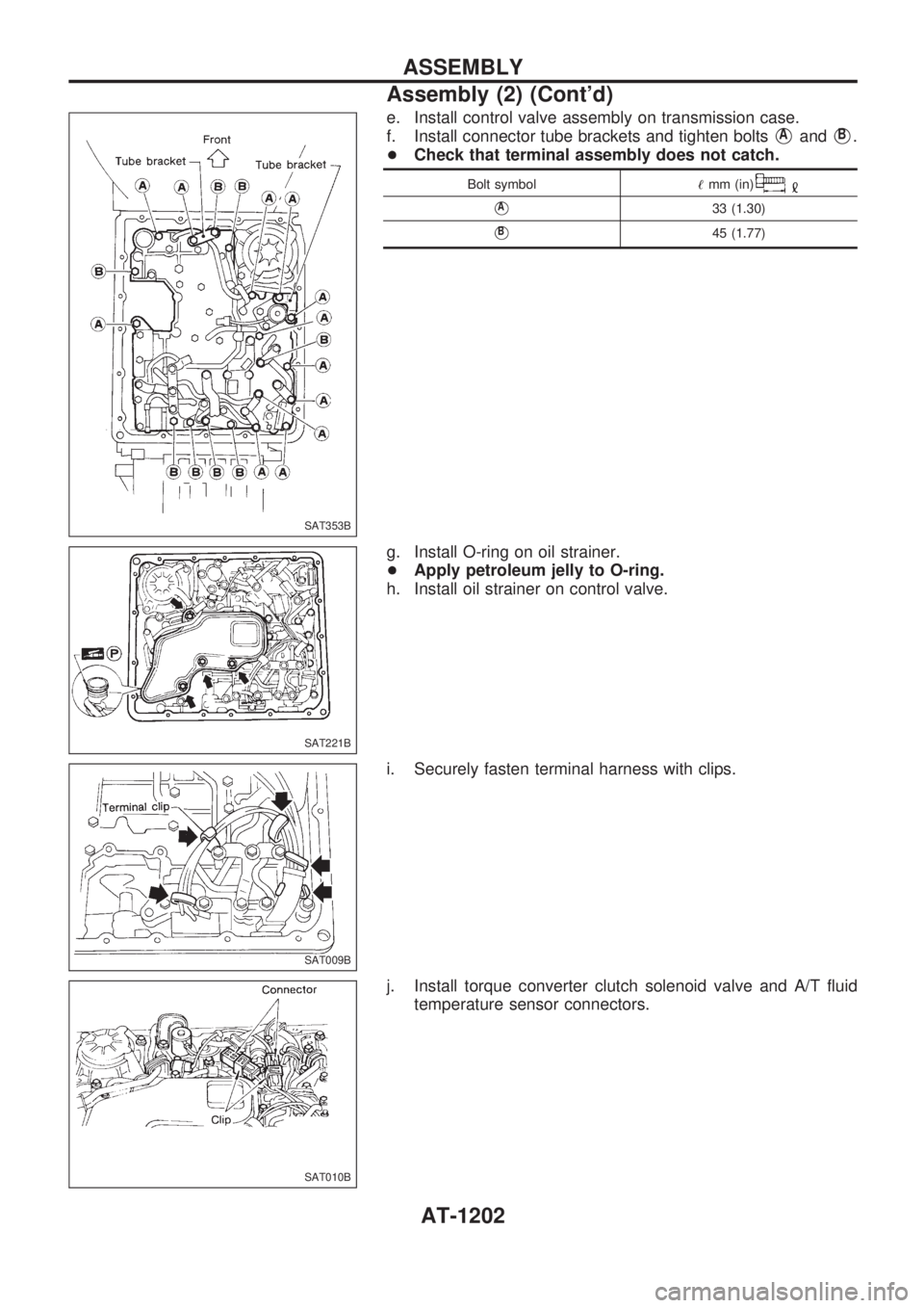
e. Install control valve assembly on transmission case.
f. Install connector tube brackets and tighten bolts
VAandVB.
+Check that terminal assembly does not catch.
Bolt symbol!mm (in)
VA33 (1.30)
VB45 (1.77)
g. Install O-ring on oil strainer.
+Apply petroleum jelly to O-ring.
h. Install oil strainer on control valve.
i. Securely fasten terminal harness with clips.
j. Install torque converter clutch solenoid valve and A/T fluid
temperature sensor connectors.
SAT353B
SAT221B
SAT009B
SAT010B
ASSEMBLY
Assembly (2) (Cont'd)
AT-1202
Page 220 of 1033
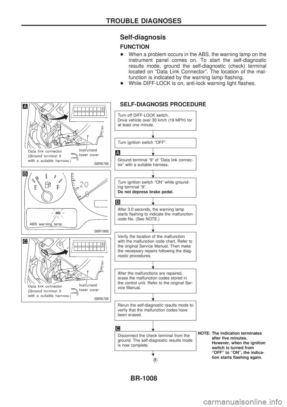
Self-diagnosis
FUNCTION
+When a problem occurs in the ABS, the warning lamp on the
instrument panel comes on. To start the self-diagnostic
results mode, ground the self-diagnostic (check) terminal
located on ªData Link Connectorº. The location of the mal-
function is indicated by the warning lamp flashing.
+While DIFF-LOCK is on, anti-lock warning light flashes.
SELF-DIAGNOSIS PROCEDURE
Turn off DIFF-LOCK switch.
Drive vehicle over 30 km/h (19 MPH) for
at least one minute.
Turn ignition switch ªOFFº.
Ground terminal ª9º of ªData link connec-
torº with a suitable harness.
Turn ignition switch ªONº while ground-
ing terminal ª9º.
Do not depress brake pedal.
After 3.0 seconds, the warning lamp
starts flashing to indicate the malfunction
code No. (See NOTE.)
Verify the location of the malfunction
with the malfunction code chart. Refer to
the original Service Manual. Then make
the necessary repairs following the diag-
nostic procedures.
After the malfunctions are repaired,
erase the malfunction codes stored in
the control unit. Refer to the original Ser-
vice Manual.
Rerun the self-diagnostic results mode to
verify that the malfunction codes have
been erased.
Disconnect the check terminal from the
ground. The self-diagnostic results mode
is now complete.NOTE: The indication terminates
after five minutes.
However, when the ignition
switch is turned from
ªOFFº to ªONº, the indica-
tion starts flashing again.
VA
SBR679E
SBR186E
SBR679E
.
.
.
.
.
.
.
.
.
TROUBLE DIAGNOSES
BR-1008