torque NISSAN PATROL 2000 Electronic Manual PDF
[x] Cancel search | Manufacturer: NISSAN, Model Year: 2000, Model line: PATROL, Model: NISSAN PATROL 2000Pages: 1033, PDF Size: 30.71 MB
Page 859 of 1033
+Allow components stored in cool areas to warm to working area temperature before removing
seal caps. This prevents condensation from forming inside A/C components.
+Thoroughly remove moisture from the refrigeration system before charging the refrigerant.
+Always replace used O-rings.
+When connecting tube, apply lubricant to circle of the O-rings shown in illustration. Be careful
not to apply lubricant to threaded portion.
Lubricant name: Nissan A/C System Oil Type S
Part number: KLH00-PAGS0
+O-ring must be closely attached to dented portion of tube.
+When replacing the O-ring, be careful not to damage O-ring and tube.
+Connect tube until you hear it click, then tighten the nut or bolt by hand until snug. Make sure
that the O-ring is installed to tube correctly.
+After connecting line, conduct leak test and make sure that there is no leakage from connections.
When the gas leaking point is found, disconnect that line and replace the O-ring. Then tighten
connections of seal seat to the specified torque.
PRECAUTIONS AND PREPARATION
Precautions for Refrigerant Connection
(Cont'd)
HA-1004
Page 881 of 1033
Engine coolant temperature sensor
(ECTS) .............................................. EC-1092
Engine oil filter replacement ................. MA-1013
Engine oil replacement ......................... MA-1012
Engine removal ..................................... EM-1064
Engine serial number ............................. GI-1008
F
F/FOG - Wiring diagram ........................ EL-1052
Final drive disassembly .............. PD-1004, 1005
Fluid temperature sensor (A/T) ............. AT-1081
Fluids .................................................... MA-1008
Flywheel runout .................................... EM-1095
Fog lamp, front ...................................... EL-1052
Fog lamp, rear ....................................... EL-1053
Forward clutch ....................................... AT-1167
Front axle .............................................. FA-1002
Front final drive disassembly (4WD) .... PD-1004
Front fog lamp ....................................... EL-1052
Front passenger air bag ....................... RS-1003
Front seat .............................................. BT-1006
Front washer .......................................... EL-1098
Front wiper ............................................. EL-1098
Fuel cut control (at no load & high
engine speed) ................................... EC-1021
Fuel filter replacement .......................... MA-1017
Fuel gauge ............................................. EL-1073
Fuel injection system ............................ EC-1019
Fuel line inspection ............................... MA-1018
Fuel precautions ..................................... GI-1002
Fuse block ............................................. EL-1229
Fuse ....................................................... EL-1230
Fusible link ............................................. EL-1230
G
GLOW - Wiring diagram ....................... EC-1221
Gauges .................................................. EL-1073
Glow plug .............................................. EC-1221
Glow relay ............................................. EC-1221
Grease ........................................ MA-1008, 1016
Ground distribution ................................ EL-1013
H
HEAT UP - Wiring diagram .................. EC-1242
HEATER - Wiring diagram .................... HA-1005
HLC - Wiring diagram ............................ EL-1099
HORN - Wiring diagram ........................ EL-1100
Harness layout ....................................... EL-1191
Hazard warning lamp ............................ EL-1058
Headlamp washer .................................. EL-1099
Headlamp wiper ..................................... EL-1099
Headlamp .............................................. EL-1044
Heat up switch ...................................... EC-1241
High clutch ............................................. AT-1165Horn ....................................................... EL-1100
How to erase DTC for OBD system ..... EC-1032
I
ILL - Wiring diagram .............................. EL-1061
Identification plate .................................. GI-1008
Idle speed ............................................. EC-1049
Illumination ............................................. EL-1060
Injection nozzle ..................................... EC-1023
Intake manifold ..................................... EM-1012
Interior lamp ........................................... EL-1067
Interior ................................................... BT-1004
J
Junction box (J/B) .................................. EL-1229
L
License lamp ......................................... EL-1046
Lifting points ........................................... GI-1009
Line pressure solenoid valve ................ AT-1086
Line pressure test (A/T) ........................ AT-1044
Liquid gasket application ...................... EM-1003
Location of electrical units ..................... EL-1185
Low and reverse brake ......................... AT-1171
Lubricants ............................................. MA-1008
Luggage room lamp .............................. EL-1067
M
MAFS - Wiring diagram ........................ EC-1086
MAIN - Wiring diagram ......................... EC-1077
MAJOR OVERHALL .............................. AT-1129
METER - Wiring diagram ...................... EL-1073
Maintenance (engine) ........................... MA-1011
Malfunction indicator lamp (MIL) .......... EC-1033
Manifold tightening torque (intake &
exhaust) ............................................ MA-1011
Mass air flow sensor (MAFS) ............... EC-1086
Meter ...................................................... EL-1073
Mirror, door ............................................ BT-1007
Mirror, outside ....................................... BT-1007
Model variation ....................................... GI-1005
N
NATS (Nissan Anti-theft System) .......... EL-1163
NATS - Wiring diagram ......................... EL-1166
NVH troubleshooting (EM) ................... EM-1008
ALPHABETICAL INDEX
IDX-1003
Page 882 of 1033
O
Oil change (capacity) ............................ MA-1008
Oil pan (engine) .................................... EM-1022
Oil pump (A/T) ....................................... AT-1144
Oil seal replacement (engine) .............. EM-1051
On board diagnostic system ................. EC-1032
Operating cylinder (clutch) .................... CL-1003
Outside mirror ........................................ BT-1007
Overdrive control switch ........................ AT-1095
Overrun clutch solenoid valve ............... AT-1075
Overrun clutch ....................................... AT-1167
Oversize piston ..................................... EM-1075
P
P/ANT - Wiring diagram ........................ EL-1109
PCV (positive crankcase ventilation) .... EC-1022
PNP/SW - Wiring diagram .................... EC-1233
POWER - Wiring diagram ..................... EL-1005
Park/Neutral position switch ................. EC-1233
Park/neutral position switch (A/T) ......... AT-1095
Parking lamp .......................................... EL-1046
Pilot bushing replacement - See Pilot
converter ........................................... EM-1083
Piston pin inspection ............................ EM-1072
Piston ring inspection ........................... EM-1073
Piston to bore clearance ...................... EM-1076
Power antenna ...................................... EL-1109
Power supply routing ............................. EL-1004
Power window ....................................... EL-1115
Pressure test (A/T) ................................ AT-1044
Priming pump ........................................ EC-1049
Propeller shaft on vehicle service ......... PD-1003
Propeller shaft vibration ........................ PD-1003
Propeller shaft ....................................... PD-1002
Q
Quick-glow system ................................ EC-1221
R
R/COOL - Wiring diagram
(front auto A/C) ....................... HA-1013, 1017
R/COOL - Wiring diagram (front
manual A/C) ...................................... HA-1019
R/HEAT - Wiring diagram ..................... HA-1006
ROOM/L - Wiring diagram ..................... EL-1068
Radio - See Audio ................................. EL-1108
Rear cooler - Wiring diagram (front
auto A/C) ................................. HA-1013, 1017
Rear cooler - Wiring diagram (front
manual A/C) ...................................... HA-1019
Rear fog lamp ........................................ EL-1053
Rear heater - Wiring diagram ............... HA-1006Rear window defogger .......................... EL-1101
Refrigerant lines .................................... HA-1021
Removal and installation (A/T) .............. AT-1127
Reverse clutch ....................................... AT-1161
Revolution sensor (A/T) ........................ AT-1065
Room lamp - See Interior lamp ............. EL-1067
S
S/LOCK - Wiring diagram ...................... EL-1128
S/TANK - Wiring diagram ...................... FE-1003
SHIFT - Wiring diagram ........................ AT-1117
SRS - See Supplemental Restraint
System .............................................. RS-1003
STAB - Wiring diagram ......................... RA-1002
START - Wiring diagram ....................... EL-1036
SWL/V - Wiring diagram ....................... EC-1248
Screw jack .............................................. GI-1009
Seat belt pre-tensioner disposal ........... RS-1015
Seat belt pre-tensioner ......................... RS-1003
Seat, front .............................................. BT-1006
Self-diagnostic results ........................... EC-1034
Shift lock system ................................... AT-1116
Shift schedule ........................................ AT-1206
Shift solenoid valve A (A/T) .................. AT-1071
Shift solenoid valve B (A/T) .................. AT-1073
Side air bag ........................................... RS-1003
Speedometer ......................................... EL-1073
Spiral cable ........................................... RS-1009
Stabilizer release device - Wiring
diagram ............................................. RA-1002
Stabilizer release device ....................... RA-1002
Stall test (A/T) ....................................... AT-1041
Start signal ............................................ EC-1230
Starter .................................................... EL-1039
Starting system ...................................... EL-1036
Steering switch ...................................... EL-1043
Stop lamp .............................................. EL-1050
Super lock ................................... EL-1124, 1159
Supplemental Restraint System ........... RS-1003
Supplemental restraint system - Wiring
diagram ................................... RS-1024, 1028
Swirl control valve control solenoid
valve .................................................. EC-1246
Symptom matrix chart ........................... EC-1055
T
TCM circuit diagram .............................. AT-1008
TCM inspection table ............................ AT-1060
Tachometer ............................................ EL-1073
Tail lamp ................................................ EL-1046
Throttle position switch .......................... AT-1096
Timing chain ......................................... EM-1027
Timing gear ........................................... EM-1039
Torque converter clutch solenoid
valve .................................................. AT-1078
Torque converter installation ................. AT-1128
ALPHABETICAL INDEX
IDX-1004
Page 899 of 1033
MAINTENANCE
SECTION
MA
MODIFICATION NOTICE:
+ The ZD30DDTi engine has been replaced with the RD28ETi engine.
+ Descriptions for the engine coolant mixture ratio have been modified.
CONTENTS
PERIODIC MAINTENANCE ................................ 1002
Maintenance Schedule for Diesel Engines
(Annual Mileage < 30,000 km/year) ................ 1002
Chassis and Body Maintenance ...................... 1003
Maintenance Under Severe Driving Conditions
(Annual Driving Distance < 30,000 km/year)... 1004
Maintenance Schedule for Diesel Engines
(Annual Mileage > 30,000 km/year) ................ 1005
Chassis and Body Maintenance ...................... 1006
Maintenance Under Severe Driving Conditions
(AnnualDrivingDistance>30,000km/year)...1007
RECOMMENDED FLUIDS AND
LUBRICANTS ...................................................... 1008
Fluids and Lubricants....................................... 1008
SAE Viscosity Number..................................... 1009
Engine Coolant Mixture Ratio .......................... 1010
ZD
ENGINE MAINTENANCE .................................... 1011
Checking Tightening Torque............................ 1011 Adjusting Intake and Exhaust Valve
Clearance ......................................................... 1011
Checking Drive Belt ......................................... 1011
Removal ........................................................... 1012
Installation ........................................................ 1012
Changing Engine Oil ........................................ 1012
Changing Engine Oil Filter............................... 1013
Changing Engine Coolant ................................ 1014
Checking Cooling System................................ 1016
Checking and Replacing Fuel Filter and
Draining Water ................................................. 1017
Checking Fuel Lines ........................................ 1018
Cleaning and Replacing Air Cleaner Filter ...... 1019
CHASSIS AND BODY MAINTENANCE ............. 1020
Checking A/T Fluid .......................................... 1020
Changing A/T Fluid .......................................... 1021
SERVICE DATA AND SPECIFICATIONS
(SDS) .................................................................... 1022
Engine Maintenance (ZD) ................................ 1022
MA
Page 909 of 1033
Checking Tightening Torque
Checking should be performed while engine is cold.
MANIFOLD BOLTS AND NUTS
Intake and exhaust manifolds:
Intake
:25-28Nzm (2.5 - 2.9 kg-m, 18 - 20 ft-lb)
Exhaust
:40-49Nzm (4.0 - 4.5 kg-m, 29 - 36 ft-lb)
Adjusting Intake and Exhaust Valve
Clearance
Refer to EM section.
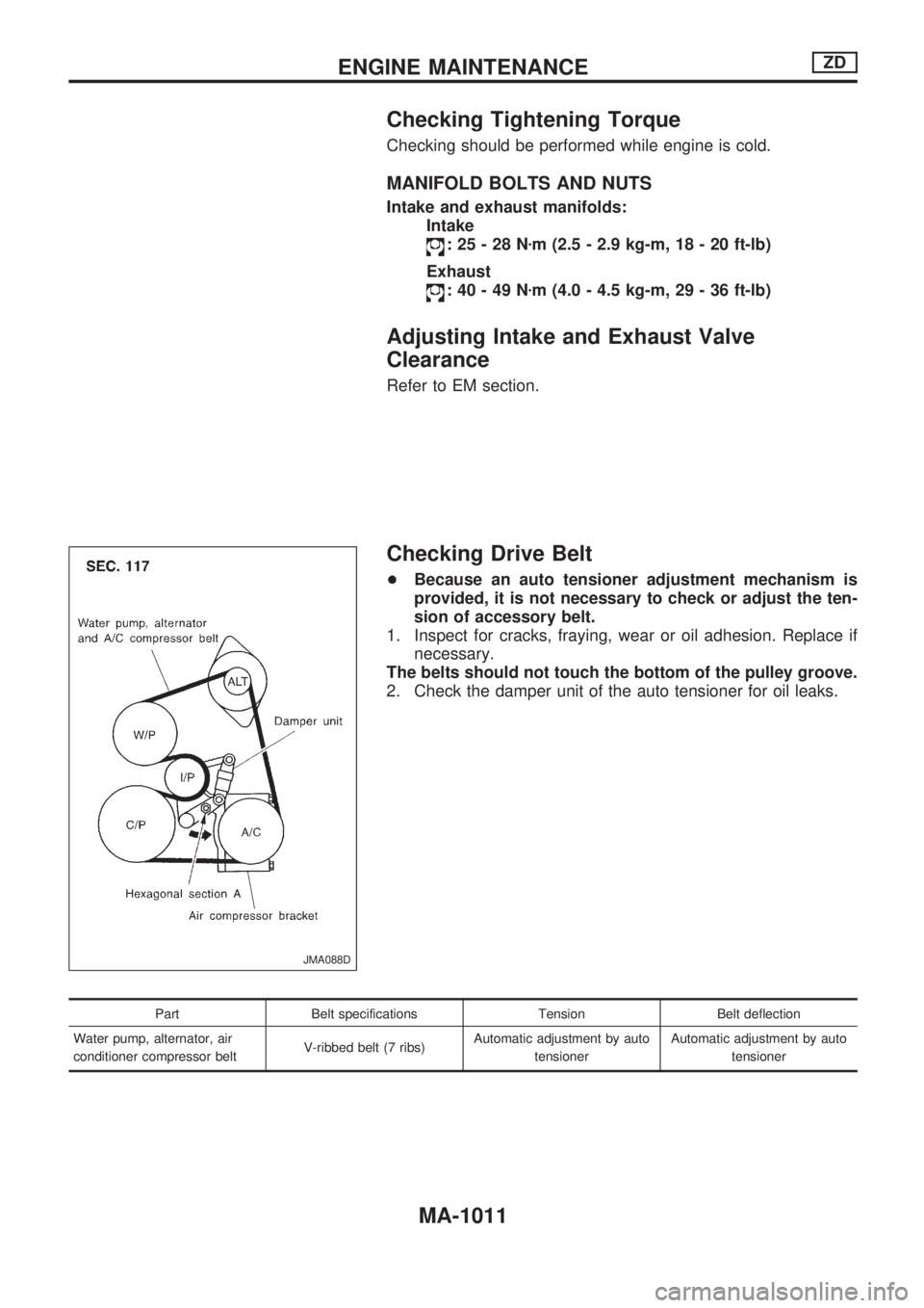
Checking Drive Belt
+Because an auto tensioner adjustment mechanism is
provided, it is not necessary to check or adjust the ten-
sion of accessory belt.
1. Inspect for cracks, fraying, wear or oil adhesion. Replace if
necessary.
The belts should not touch the bottom of the pulley groove.
2. Check the damper unit of the auto tensioner for oil leaks.
Part Belt specifications Tension Belt deflection
Water pump, alternator, air
conditioner compressor beltV-ribbed belt (7 ribs)Automatic adjustment by auto
tensionerAutomatic adjustment by auto
tensioner
JMA088D
ENGINE MAINTENANCEZD
MA-1011
Page 919 of 1033
Changing A/T Fluid
1. Warm up A/T fluid.
2. Stop engine.
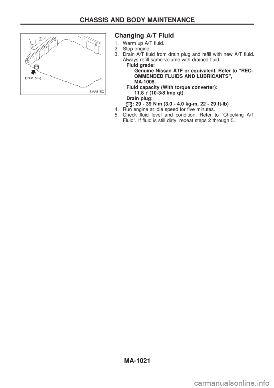
3. Drain A/T fluid from drain plug and refill with new A/T fluid.
Always refill same volume with drained fluid.
Fluid grade:
Genuine Nissan ATF or equivalent. Refer to ªREC-
OMMENDED FLUIDS AND LUBRICANTSº,
MA-1008.
Fluid capacity (With torque converter):
11.8!(10-3/8 Imp qt)
Drain plug:
:29-39Nzm (3.0 - 4.0 kg-m, 22 - 29 ft-lb)
4. Run engine at idle speed for five minutes.
5. Check fluid level and condition. Refer to ªChecking A/T
Fluidº. If fluid is still dirty, repeat steps 2 through 5.
SMA515C
CHASSIS AND BODY MAINTENANCE
MA-1021
Page 928 of 1033
Installation
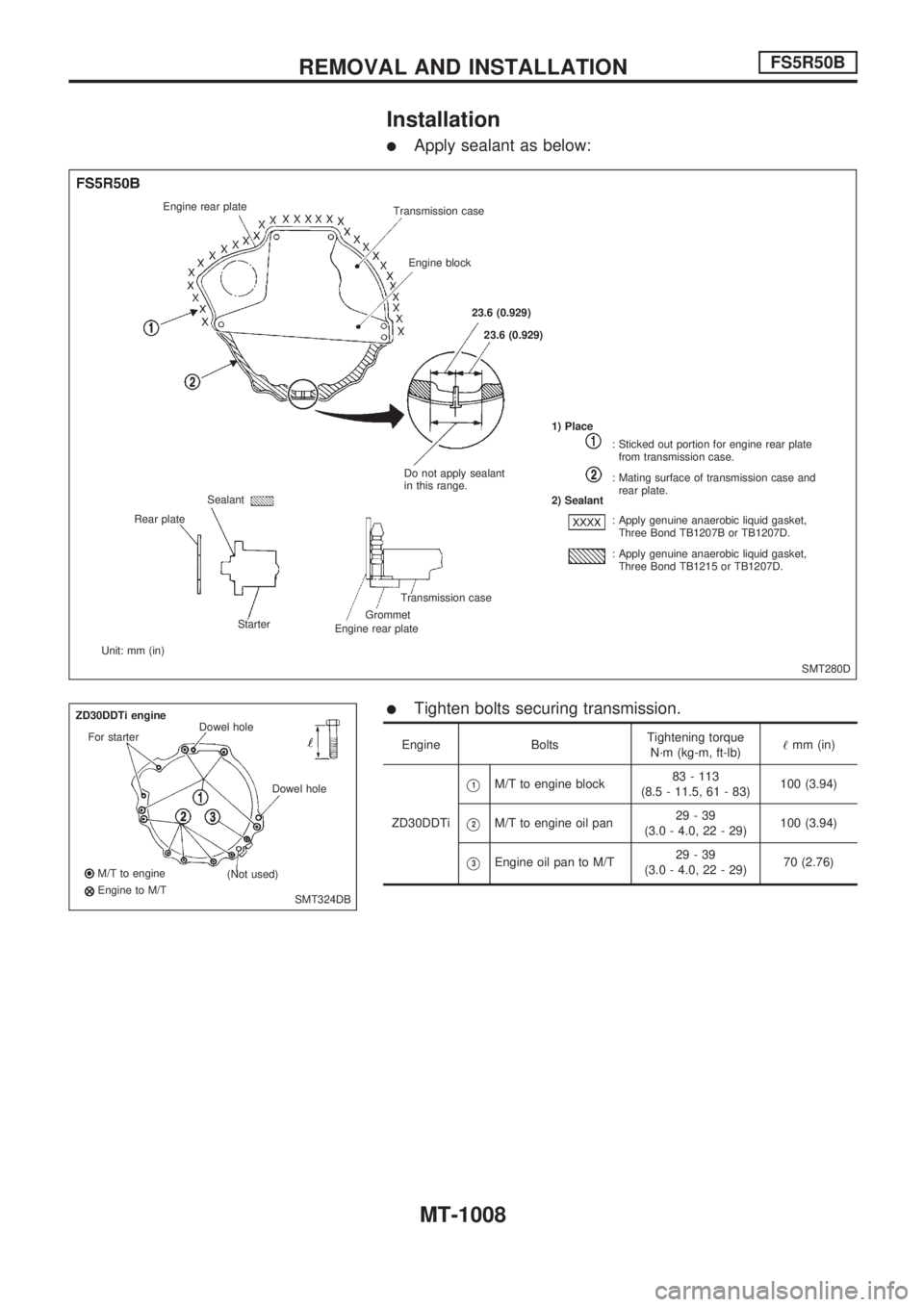
lApply sealant as below:
lTighten bolts securing transmission.
Engine BoltsTightening torque
N´m (kg-m, ft-lb)!mm (in)
ZD30DDTi
V1M/T to engine block83 - 113
(8.5 - 11.5, 61 - 83)100 (3.94)
V2M/T to engine oil pan29-39
(3.0 - 4.0, 22 - 29)100 (3.94)
V3Engine oil pan to M/T29-39
(3.0 - 4.0, 22 - 29)70 (2.76)
SMT280D Engine rear plate
Transmission case
Engine block
23.6 (0.929)
23.6 (0.929)
Do not apply sealant
in this range.1) Place
2) Sealant
: Sticked out portion for engine rear plate
from transmission case.
: Mating surface of transmission case and
rear plate.
: Apply genuine anaerobic liquid gasket,
Three Bond TB1207B or TB1207D.
: Apply genuine anaerobic liquid gasket,
Three Bond TB1215 or TB1207D.
Transmission case
Grommet
Engine rear plate Starter Sealant
Rear plate
Unit: mm (in)
SMT324DB ZD30DDTi engine
For starterDowel hole
Dowel hole
(Not used) M/T to engine
Engine to M/T
REMOVAL AND INSTALLATIONFS5R50B
MT-1008
Page 953 of 1033
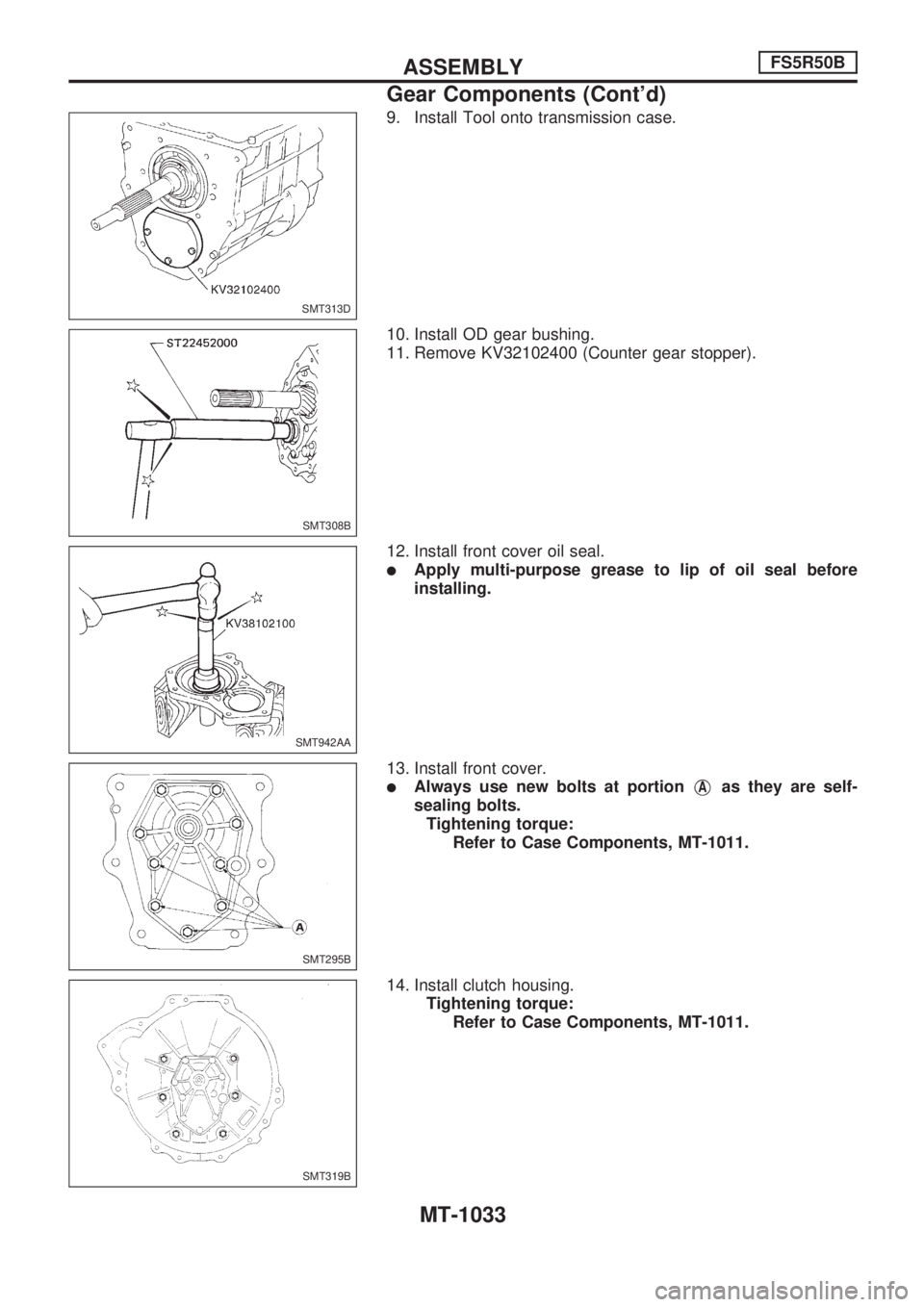
9. Install Tool onto transmission case.
10. Install OD gear bushing.
11. Remove KV32102400 (Counter gear stopper).
12. Install front cover oil seal.
lApply multi-purpose grease to lip of oil seal before
installing.
13. Install front cover.
lAlways use new bolts at portionVAas they are self-
sealing bolts.
Tightening torque:
Refer to Case Components, MT-1011.
14. Install clutch housing.
Tightening torque:
Refer to Case Components, MT-1011.
SMT313D
SMT308B
SMT942AA
SMT295B
SMT319B
ASSEMBLYFS5R50B
Gear Components (Cont'd)
MT-1033
Page 956 of 1033
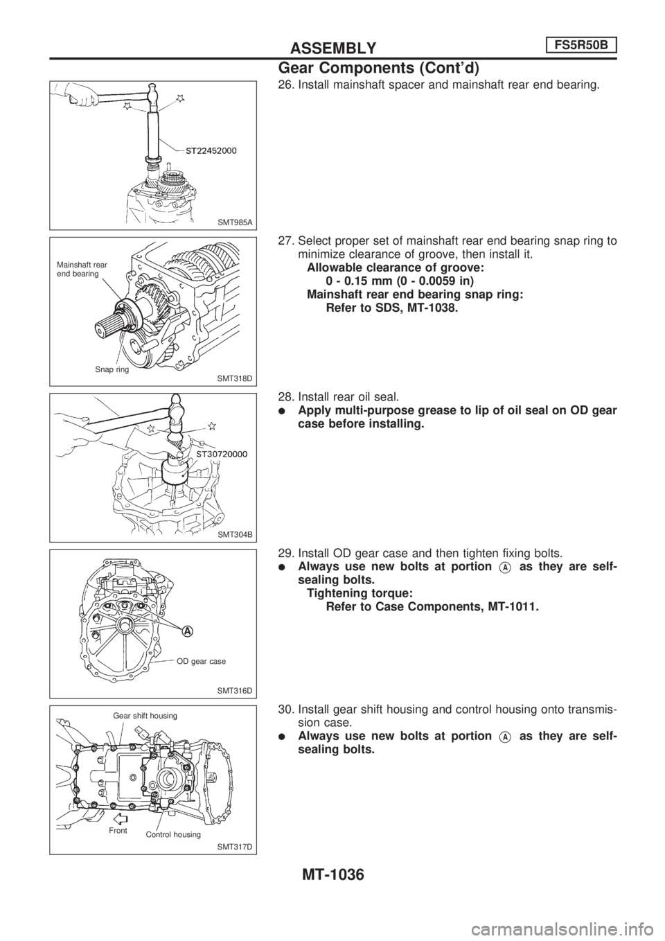
26. Install mainshaft spacer and mainshaft rear end bearing.
27. Select proper set of mainshaft rear end bearing snap ring to
minimize clearance of groove, then install it.
Allowable clearance of groove:
0 - 0.15 mm (0 - 0.0059 in)
Mainshaft rear end bearing snap ring:
Refer to SDS, MT-1038.
28. Install rear oil seal.
lApply multi-purpose grease to lip of oil seal on OD gear
case before installing.
29. Install OD gear case and then tighten fixing bolts.
lAlways use new bolts at portionVAas they are self-
sealing bolts.
Tightening torque:
Refer to Case Components, MT-1011.
30. Install gear shift housing and control housing onto transmis-
sion case.
lAlways use new bolts at portionVAas they are self-
sealing bolts.
SMT985A
SMT318D Mainshaft rear
end bearing
Snap ring
SMT304B
SMT316D OD gear case
SMT317D Gear shift housing
Control housing Front
ASSEMBLYFS5R50B
Gear Components (Cont'd)
MT-1036
Page 1031 of 1033
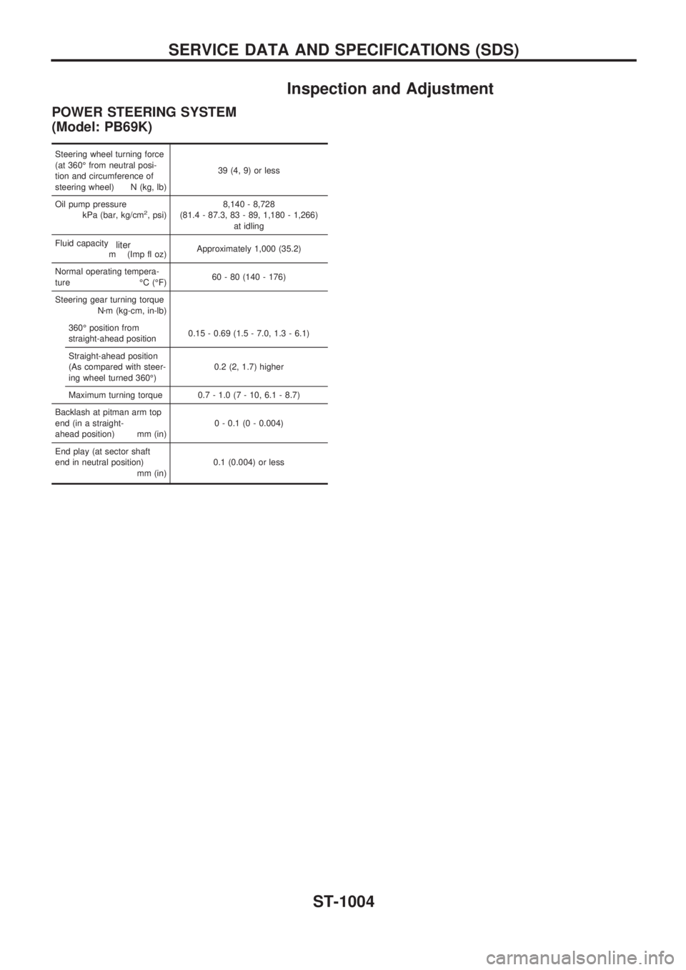
Inspection and Adjustment
POWER STEERING SYSTEM
(Model: PB69K)
Steering wheel turning force
(at 360É from neutral posi-
tion and circumference of
steering wheel) N (kg, lb)39 (4, 9) or less
Oil pump pressure
kPa (bar, kg/cm
2, psi)8,140 - 8,728
(81.4 - 87.3, 83 - 89, 1,180 - 1,266)
at idling
Fluid capacity
m
liter(Imp fl oz)Approximately 1,000 (35.2)
Normal operating tempera-
ture ÉC (ÉF)60 - 80 (140 - 176)
Steering gear turning torque
Nzm (kg-cm, in-lb)
360É position from
straight-ahead position0.15 - 0.69 (1.5 - 7.0, 1.3 - 6.1)
Straight-ahead position
(As compared with steer-
ing wheel turned 360É)0.2 (2, 1.7) higher
Maximum turning torque 0.7 - 1.0 (7 - 10, 6.1 - 8.7)
Backlash at pitman arm top
end (in a straight-
ahead position) mm (in)0 - 0.1 (0 - 0.004)
End play (at sector shaft
end in neutral position)
mm (in)0.1 (0.004) or less
SERVICE DATA AND SPECIFICATIONS (SDS)
ST-1004