NISSAN PATROL 2001 Electronic Repair Manual
Manufacturer: NISSAN, Model Year: 2001, Model line: PATROL, Model: NISSAN PATROL 2001Pages: 273, PDF Size: 9.05 MB
Page 261 of 273
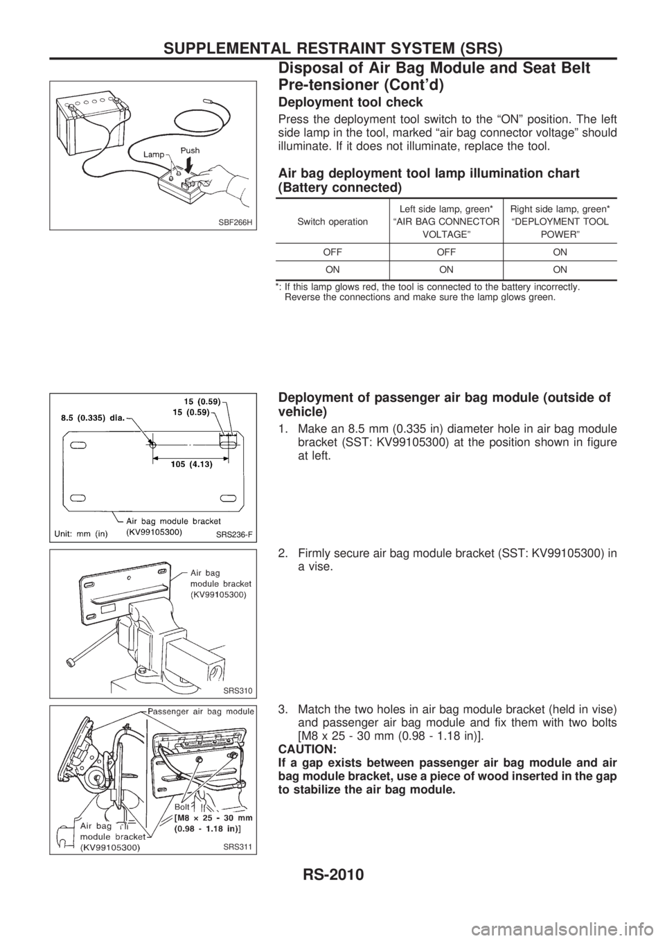
Deployment tool check
Press the deployment tool switch to the ªONº position. The left
side lamp in the tool, marked ªair bag connector voltageº should
illuminate. If it does not illuminate, replace the tool.
Air bag deployment tool lamp illumination chart
(Battery connected)
Switch operationLeft side lamp, green*
ªAIR BAG CONNECTOR
VOLTAGEºRight side lamp, green*
ªDEPLOYMENT TOOL
POWERº
OFF OFF ON
ON ON ON
*: If this lamp glows red, the tool is connected to the battery incorrectly.
Reverse the connections and make sure the lamp glows green.
Deployment of passenger air bag module (outside of
vehicle)
1. Make an 8.5 mm (0.335 in) diameter hole in air bag module
bracket (SST: KV99105300) at the position shown in figure
at left.
2. Firmly secure air bag module bracket (SST: KV99105300) in
a vise.
3. Match the two holes in air bag module bracket (held in vise)
and passenger air bag module and fix them with two bolts
[M8 x 25 - 30 mm (0.98 - 1.18 in)].
CAUTION:
If a gap exists between passenger air bag module and air
bag module bracket, use a piece of wood inserted in the gap
to stabilize the air bag module.
SBF266H
SRS236-F
SRS310
SRS311
SUPPLEMENTAL RESTRAINT SYSTEM (SRS)
Disposal of Air Bag Module and Seat Belt
Pre-tensioner (Cont'd)
RS-2010
Page 262 of 273
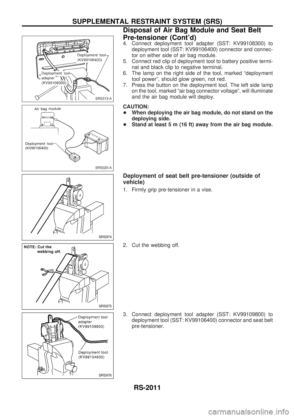
4. Connect deployment tool adapter (SST: KV99108300) to
deployment tool (SST: KV99106400) connector and connec-
tor on either side of air bag module.
5. Connect red clip of deployment tool to battery positive termi-
nal and black clip to negative terminal.
6. The lamp on the right side of the tool, marked ªdeployment
tool powerº, should glow green, not red.
7. Press the button on the deployment tool. The left side lamp
on the tool, marked ªair bag connector voltageº, will illuminate
and the air bag module will deploy.
CAUTION:
+When deploying the air bag module, do not stand on the
deploying side.
+Stand at least 5 m (16 ft) away from the air bag module.
Deployment of seat belt pre-tensioner (outside of
vehicle)
1. Firmly grip pre-tensioner in a vise.
2. Cut the webbing off.
3. Connect deployment tool adapter (SST: KV99109800) to
deployment tool (SST: KV99106400) connector and seat belt
pre-tensioner.
SRS313-A
SRS020-A
SRS974
SRS975
SRS976
SUPPLEMENTAL RESTRAINT SYSTEM (SRS)
Disposal of Air Bag Module and Seat Belt
Pre-tensioner (Cont'd)
RS-2011
Page 263 of 273
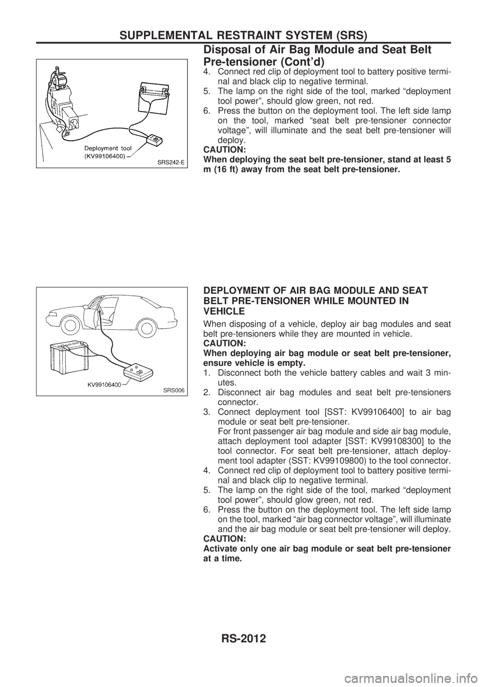
4. Connect red clip of deployment tool to battery positive termi-
nal and black clip to negative terminal.
5. The lamp on the right side of the tool, marked ªdeployment
tool powerº, should glow green, not red.
6. Press the button on the deployment tool. The left side lamp
on the tool, marked ªseat belt pre-tensioner connector
voltageº, will illuminate and the seat belt pre-tensioner will
deploy.
CAUTION:
When deploying the seat belt pre-tensioner, stand at least 5
m (16 ft) away from the seat belt pre-tensioner.
DEPLOYMENT OF AIR BAG MODULE AND SEAT
BELT PRE-TENSIONER WHILE MOUNTED IN
VEHICLE
When disposing of a vehicle, deploy air bag modules and seat
belt pre-tensioners while they are mounted in vehicle.
CAUTION:
When deploying air bag module or seat belt pre-tensioner,
ensure vehicle is empty.
1. Disconnect both the vehicle battery cables and wait 3 min-
utes.
2. Disconnect air bag modules and seat belt pre-tensioners
connector.
3. Connect deployment tool [SST: KV99106400] to air bag
module or seat belt pre-tensioner.
For front passenger air bag module and side air bag module,
attach deployment tool adapter [SST: KV99108300] to the
tool connector. For seat belt pre-tensioner, attach deploy-
ment tool adapter (SST: KV99109800) to the tool connector.
4. Connect red clip of deployment tool to battery positive termi-
nal and black clip to negative terminal.
5. The lamp on the right side of the tool, marked ªdeployment
tool powerº, should glow green, not red.
6. Press the button on the deployment tool. The left side lamp
on the tool, marked ªair bag connector voltageº, will illuminate
and the air bag module or seat belt pre-tensioner will deploy.
CAUTION:
Activate only one air bag module or seat belt pre-tensioner
at a time.
SRS242-E
SRS006
SUPPLEMENTAL RESTRAINT SYSTEM (SRS)
Disposal of Air Bag Module and Seat Belt
Pre-tensioner (Cont'd)
RS-2012
Page 264 of 273
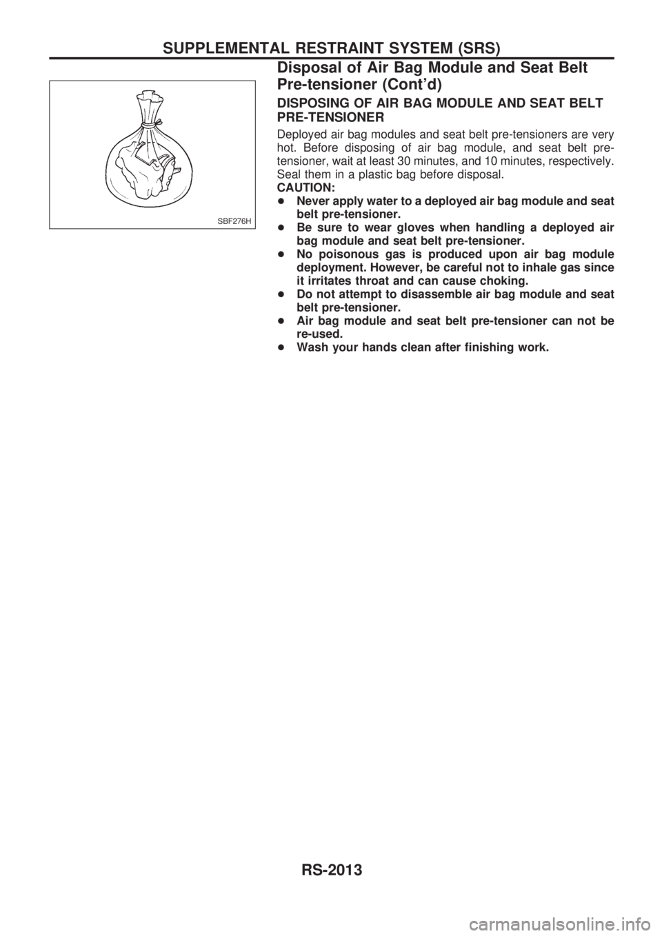
DISPOSING OF AIR BAG MODULE AND SEAT BELT
PRE-TENSIONER
Deployed air bag modules and seat belt pre-tensioners are very
hot. Before disposing of air bag module, and seat belt pre-
tensioner, wait at least 30 minutes, and 10 minutes, respectively.
Seal them in a plastic bag before disposal.
CAUTION:
+Never apply water to a deployed air bag module and seat
belt pre-tensioner.
+Be sure to wear gloves when handling a deployed air
bag module and seat belt pre-tensioner.
+No poisonous gas is produced upon air bag module
deployment. However, be careful not to inhale gas since
it irritates throat and can cause choking.
+Do not attempt to disassemble air bag module and seat
belt pre-tensioner.
+Air bag module and seat belt pre-tensioner can not be
re-used.
+Wash your hands clean after finishing work.
SBF276H
SUPPLEMENTAL RESTRAINT SYSTEM (SRS)
Disposal of Air Bag Module and Seat Belt
Pre-tensioner (Cont'd)
RS-2013
Page 265 of 273
Trouble Diagnoses Introduction
CAUTION:
+Do not use electrical test equipment to check SRS harness connectors unless instructed to in
this Service Manual. SRS wiring harnesses can be identified by yellow harness connector.
+Do not attempt to repair, splice or modify the SRS wiring harness. If the harness is damaged,
replace it with a new one.
+Keep ground portion clean.
DIAGNOSIS FUNCTION
The SRS self-diagnosis results can be read by using ªAIR BAGº warning lamp and/or CONSULT-II. The
reading of these results is accomplished using one of two modes Ð ªUser modeº and ªDiagnosis modeº.
The User mode is exclusively prepared for the customer (driver). This mode warns the driver of a system
malfunction through the operation of the ªAIR BAGº warning lamp.
The Diagnosis mode allows the technician to locate and inspect the malfunctioning part.
The mode applications for the ªAIR BAGº warning lamp and CONSULT-II are as follows:
User mode Diagnosis mode Display type
ªAIR BAGº warning lamp X X ON-OFF operation
CONSULT-II Ð X Monitoring
DIAGNOSIS MODE FOR CONSULT-II
+ªSELF-DIAG [CURRENT]º
A current Self-diagnosis result (also indicated by the warning lamp flashes in the Diagnosis mode) is
displayed on the CONSULT-II screen in real time. This refers to a malfunctioning part requiring repairs.
+ªSELF-DIAG [PAST]º
Diagnosis results previously stored in the memory are displayed on the CONSULT-II screen. The stored
results are not erased until memory erasing is executed.
+ªTROUBLE DIAG RECORDº
With TROUBLE DIAG RECORD, diagnosis results previously erased by a reset operation can be dis-
played on the CONSULT-II screen.
+ªECU DISCRIMINATED NO.º
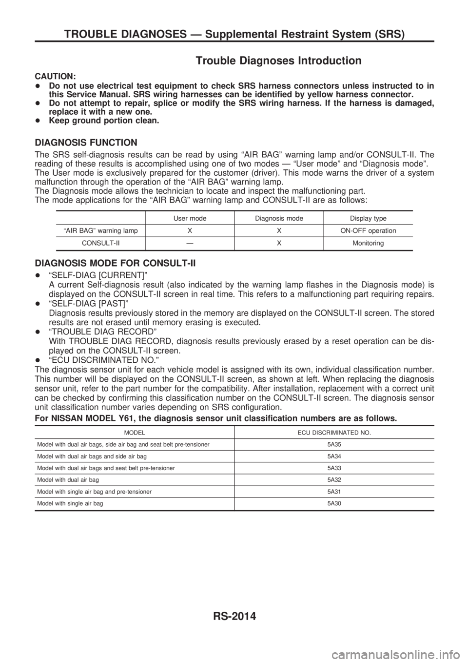
The diagnosis sensor unit for each vehicle model is assigned with its own, individual classification number.
This number will be displayed on the CONSULT-II screen, as shown at left. When replacing the diagnosis
sensor unit, refer to the part number for the compatibility. After installation, replacement with a correct unit
can be checked by confirming this classification number on the CONSULT-II screen. The diagnosis sensor
unit classification number varies depending on SRS configuration.
For NISSAN MODEL Y61, the diagnosis sensor unit classification numbers are as follows.
MODEL ECU DISCRIMINATED NO.
Model with dual air bags, side air bag and seat belt pre-tensioner 5A35
Model with dual air bags and side air bag 5A34
Model with dual air bags and seat belt pre-tensioner 5A33
Model with dual air bag5A32
Model with single air bag and pre-tensioner 5A31
Model with single air bag5A30
TROUBLE DIAGNOSES Ð Supplemental Restraint System (SRS)
RS-2014
Page 266 of 273
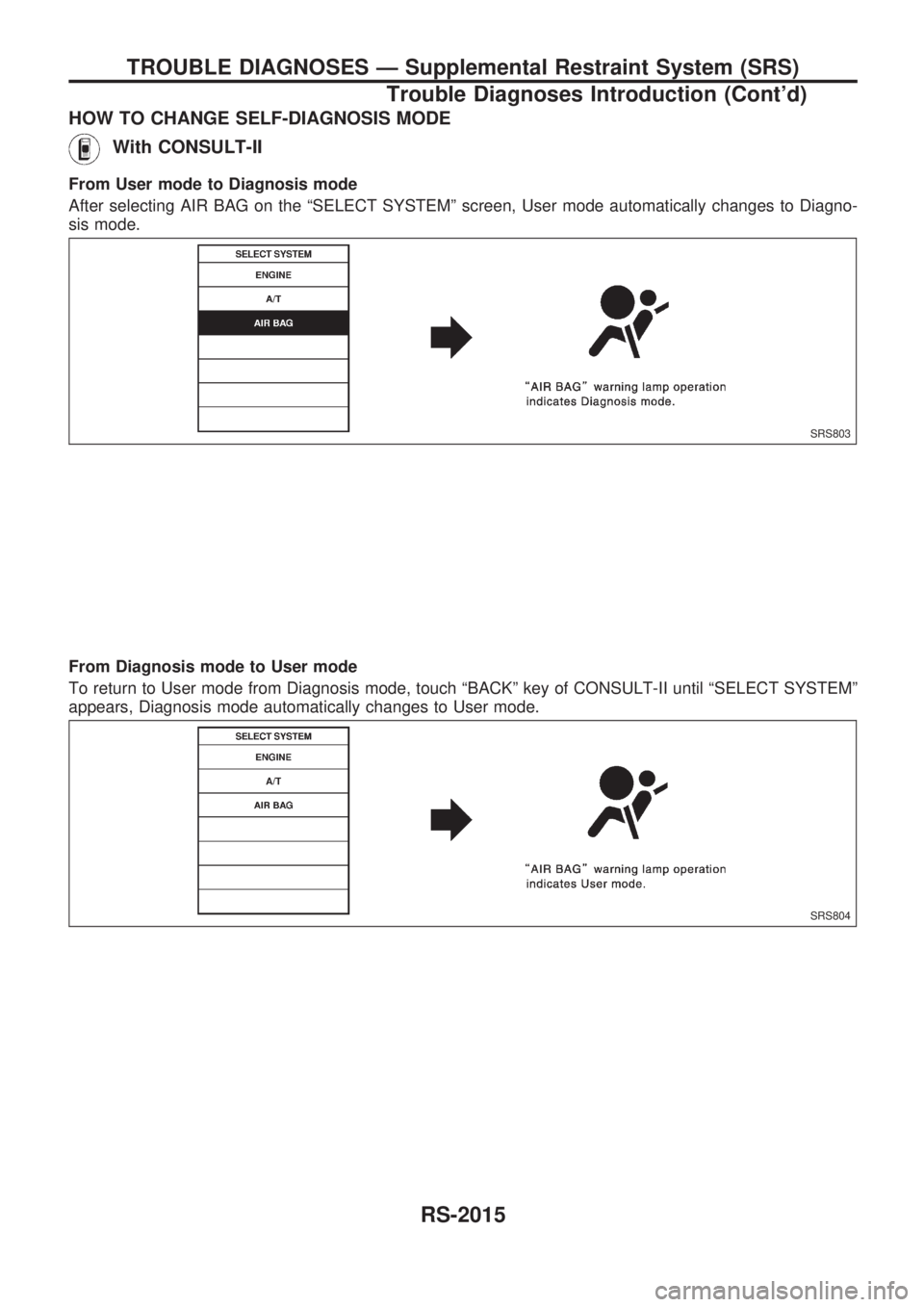
HOW TO CHANGE SELF-DIAGNOSIS MODE
With CONSULT-II
From User mode to Diagnosis mode
After selecting AIR BAG on the ªSELECT SYSTEMº screen, User mode automatically changes to Diagno-
sis mode.
From Diagnosis mode to User mode
To return to User mode from Diagnosis mode, touch ªBACKº key of CONSULT-II until ªSELECT SYSTEMº
appears, Diagnosis mode automatically changes to User mode.
SRS803
SRS804
TROUBLE DIAGNOSES Ð Supplemental Restraint System (SRS)
Trouble Diagnoses Introduction (Cont'd)
RS-2015
Page 267 of 273
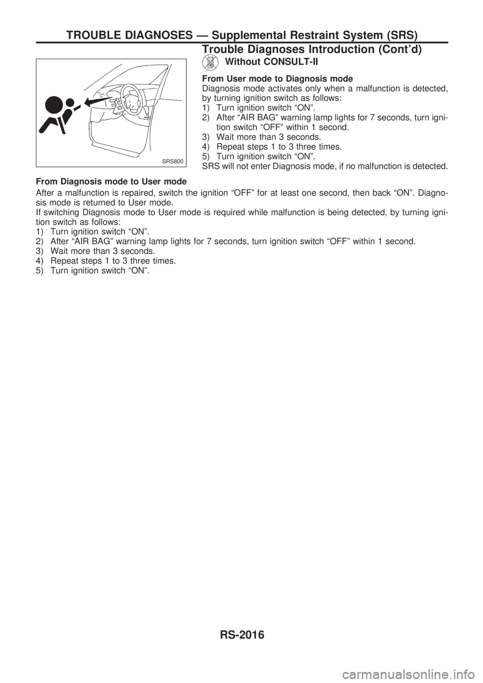
Without CONSULT-II
From User mode to Diagnosis mode
Diagnosis mode activates only when a malfunction is detected,
by turning ignition switch as follows:
1) Turn ignition switch ªONº.
2) After ªAIR BAGº warning lamp lights for 7 seconds, turn igni-
tion switch ªOFFº within 1 second.
3) Wait more than 3 seconds.
4) Repeat steps 1 to 3 three times.
5) Turn ignition switch ªONº.
SRS will not enter Diagnosis mode, if no malfunction is detected.
From Diagnosis mode to User mode
After a malfunction is repaired, switch the ignition ªOFFº for at least one second, then back ªONº. Diagno-
sis mode is returned to User mode.
If switching Diagnosis mode to User mode is required while malfunction is being detected, by turning igni-
tion switch as follows:
1) Turn ignition switch ªONº.
2) After ªAIR BAGº warning lamp lights for 7 seconds, turn ignition switch ªOFFº within 1 second.
3) Wait more than 3 seconds.
4) Repeat steps 1 to 3 three times.
5) Turn ignition switch ªONº.
SRS800
TROUBLE DIAGNOSES Ð Supplemental Restraint System (SRS)
Trouble Diagnoses Introduction (Cont'd)
RS-2016
Page 268 of 273
![NISSAN PATROL 2001 Electronic Repair Manual HOW TO ERASE SELF-DIAGNOSIS RESULTS
With CONSULT-II
+ªSELF-DIAG [CURRENT]º
A current Self-diagnosis result is displayed on the CON-
SULT-II screen in real time. After the malfunction is repaired
com NISSAN PATROL 2001 Electronic Repair Manual HOW TO ERASE SELF-DIAGNOSIS RESULTS
With CONSULT-II
+ªSELF-DIAG [CURRENT]º
A current Self-diagnosis result is displayed on the CON-
SULT-II screen in real time. After the malfunction is repaired
com](/img/5/57366/w960_57366-267.png)
HOW TO ERASE SELF-DIAGNOSIS RESULTS
With CONSULT-II
+ªSELF-DIAG [CURRENT]º
A current Self-diagnosis result is displayed on the CON-
SULT-II screen in real time. After the malfunction is repaired
completely, no malfunction is detected on ªSELF-DIAG
[CURRENT]º.
+ªSELF-DIAG [PAST]º
Return to the ªSELF-DIAG [CURRENT]º CONSULT-II screen
by pushing ªBACKº key of CONSULT-II and select ªSELF-
DIAG [CURRENT]º in ªSELECT DIAG MODEº. Touch
ªERASEº in ªSELF-DIAG [CURRENT]º mode.
NOTE:
If the memory of the malfunction in ªSELF-DIAG [PAST]º is
not erased, the User mode shows the system malfunction by
the operation of the warning lamp even if the malfunction is
repaired completely.
+ªTROUBLE DIAG RECORDº
The memory of ªTROUBLE DIAG RECORDº cannot be
erased.
Without CONSULT-II
After a malfunction is repaired, return Diagnosis mode to User
mode by switching the ignition ªOFFº for at least 1 second, then
back ªONº. At that time, the self-diagnostic result is cleared.
How to Perform Trouble Diagnoses for Quick
and Accurate Repair
A good understanding of the malfunction conditions can make troubleshooting faster and more accurate.
In general, each customer feels differently about a malfunction. It is important to fully understand the symp-
toms or conditions for a customer complaint.
INFORMATION FROM CUSTOMER
WHAT ........ Vehicle model
WHEN ....... Date, Frequencies
WHERE ..... Road conditions
HOW .......... Operating conditions, Symptoms
PRELIMINARY CHECK
Check that the following parts are in good order.
+Battery [Refer to EL section (ªBATTERYº) of Service Manual.]
+Fuse [Refer to EL section (ªFuseº, ªPOWER SUPPLY ROUTINGº) of Service Manual.]
+System component-to-harness connections
SRS701
TROUBLE DIAGNOSES Ð Supplemental Restraint System (SRS)
Trouble Diagnoses Introduction (Cont'd)
RS-2017
Page 269 of 273
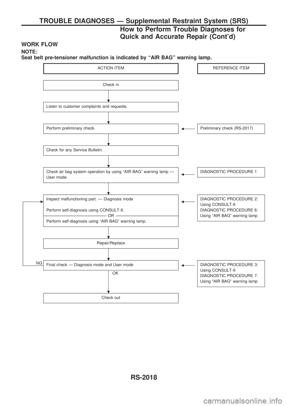
WORK FLOW
NOTE:
Seat belt pre-tensioner malfunction is indicated by ªAIR BAGº warning lamp.
ACTION ITEMREFERENCE ITEM
Check in
Listen to customer complaints and requests.
Perform preliminary check.bPreliminary check (RS-2017)
Check for any Service Bulletin.
Check air bag system operation by using ªAIR BAGº warning lamp Ð
User mode.bDIAGNOSTIC PROCEDURE 1
cInspect malfunctioning part. Ð Diagnosis mode
Perform self-diagnosis using CONSULT-II.
----------------------------------------------------------------------------------------------------------------------------------------------------------------------------------------------------------------------------------OR ----------------------------------------------------------------------------------------------------------------------------------------------------------------------------------------------------------------------------------
Perform self-diagnosis using ªAIR BAGº warning lamp.bDIAGNOSTIC PROCEDURE 2:
Using CONSULT-II
DIAGNOSTIC PROCEDURE 6:
Using ªAIR BAGº warning lamp
Repair/Replace
NGFinal check Ð Diagnosis mode and User mode
OK
bDIAGNOSTIC PROCEDURE 3:
Using CONSULT-II
DIAGNOSTIC PROCEDURE 7:
Using ªAIR BAGº warning lamp
Check out
.
.
.
.
.
.
.
.
TROUBLE DIAGNOSES Ð Supplemental Restraint System (SRS)
How to Perform Trouble Diagnoses for
Quick and Accurate Repair (Cont'd)
RS-2018
Page 270 of 273

Schematic
TRS037M
TROUBLE DIAGNOSES Ð Supplemental Restraint System (SRS)
RS-2019