brake fluid NISSAN PATROL 2002 Electronic Repair Manual
[x] Cancel search | Manufacturer: NISSAN, Model Year: 2002, Model line: PATROL, Model: NISSAN PATROL 2002Pages: 311, PDF Size: 12.08 MB
Page 25 of 311

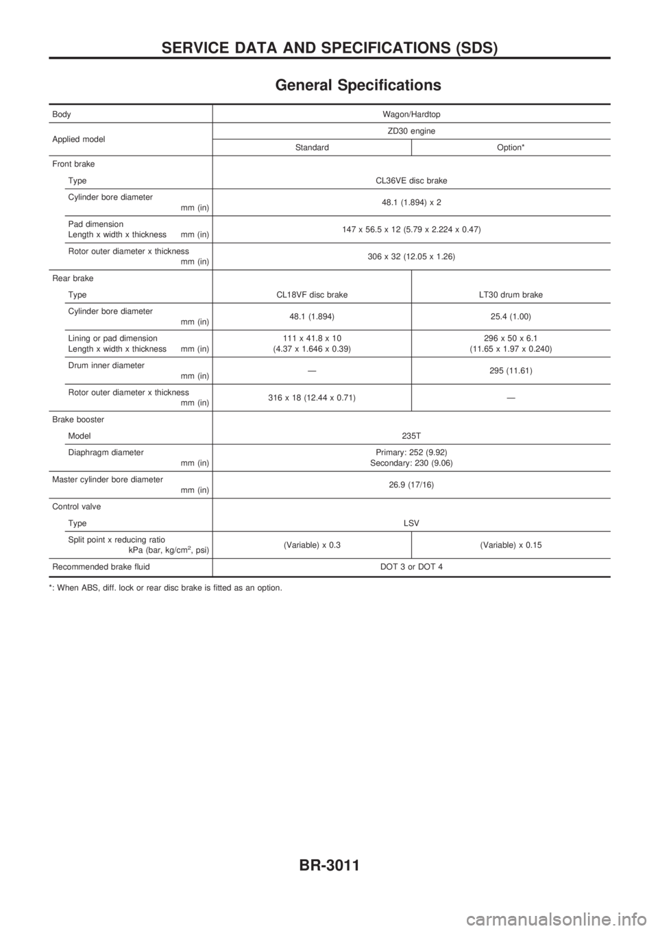
General Specifications
BodyWagon/Hardtop
Applied modelZD30 engine
Standard Option*
Front brake
TypeCL36VE disc brake
Cylinder bore diameter
mm (in)48.1 (1.894) x 2
Pad dimension
Length x width x thickness mm (in)147 x 56.5 x 12 (5.79 x 2.224 x 0.47)
Rotor outer diameter x thickness
mm (in)306 x 32 (12.05 x 1.26)
Rear brake
Type CL18VF disc brake LT30 drum brake
Cylinder bore diameter
mm (in)48.1 (1.894) 25.4 (1.00)
Lining or pad dimension
Length x width x thickness mm (in)111 x 41.8 x 10
(4.37 x 1.646 x 0.39)296x50x6.1
(11.65 x 1.97 x 0.240)
Drum inner diameter
mm (in)Ð 295 (11.61)
Rotor outer diameter x thickness
mm (in)316 x 18 (12.44 x 0.71) Ð
Brake booster
Model235T
Diaphragm diameter
mm (in)Primary: 252 (9.92)
Secondary: 230 (9.06)
Master cylinder bore diameter
mm (in)26.9 (17/16)
Control valve
TypeLSV
Split point x reducing ratio
kPa (bar, kg/cm
2, psi)(Variable) x 0.3 (Variable) x 0.15
Recommended brake fluid DOT 3 or DOT 4
*: When ABS, diff. lock or rear disc brake is fitted as an option.
SERVICE DATA AND SPECIFICATIONS (SDS)
BR-3011
Page 256 of 311

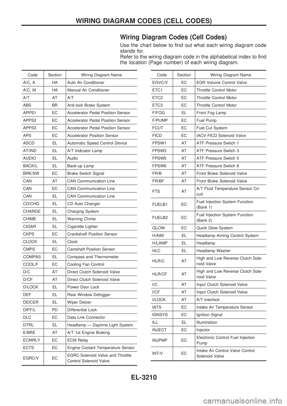
Wiring Diagram Codes (Cell Codes)
Use the chart below to find out what each wiring diagram code
stands for.
Refer to the wiring diagram code in the alphabetical index to find
the location (Page number) of each wiring diagram.
Code Section Wiring Diagram Name
A/C, A HA Auto Air Conditioner
A/C, M HA Manual Air Conditioner
A/T AT A/T
ABS BR Anti-lock Brake System
APPS1 EC Accelerator Pedal Position Sensor
APPS2 EC Accelerator Pedal Position Sensor
APPS3 EC Accelerator Pedal Position Sensor
APS EC Accelerator Position Sensor
ASCD EL Automatic Speed Control Device
AT/IND EL A/T Indicator Lamp
AUDIO EL Audio
BACK/L EL Back-up Lamp
BRK/SW EC Brake Switch Signal
CAN AT CAN Communication Line
CAN EC CAN Communication Line
CAN EL CAN Communication Line
CD/CHG EL CD Auto Changer
CHARGE EL Charging System
CHIME EL Warning Chime
CIGAR EL Cigarette Lighter
CKPS EC Crankshaft Position Sensor
CLOCK EL Clock
CMPS EC Camshaft Position Sensor
COMPAS EL Compass and Thermometer
COOL/F EC Cooling Fan Control
D/C AT Direct Clutch Solenoid Valve
D/CF AT Direct Clutch Solenoid Valve
D/LOCK EL Power Door Lock
DEF EL Rear Window Defogger
DEICER EL Wiper Deicer
DIFF/L PD Differential Lock
DLC EC Data Link Connector
DTRL EL Headlamp Ð Daytime Light System
E/BRE AT A/T 1st Engine Braking
ECMRLY EC ECM Relay
ECTS EC Engine Coolant Temperature Sensor
EGRC/V ECEGRC-Solenoid Valve and Throttle
Control Solenoid ValveCode Section Wiring Diagram Name
EGVC/V EC EGR Volume Control Valve
ETC1 EC Throttle Control Motor
ETC2 EC Throttle Control Motor
ETC3 EC Throttle Control Motor
F/FOG EL Front Fog Lamp
F/PUMP EC Fuel Pump
FCUT EC Fuel Cut System
FICD EC IACV-FICD Solenoid Valve
FPSW1 AT ATF Pressure Switch 1
FPSW3 AT ATF Pressure Switch 3
FPSW5 AT ATF Pressure Switch 5
FPSW6 AT ATF Pressure Switch 6
FR/B AT Front Brake Solenoid Valve
FR/BF AT Front Brake Solenoid Valve
FTS ATA/T Fluid Temperature Sensor Cir-
cuit
FUELB1 ECFuel Injection System Function
(Bank 1)
FUELB2 ECFuel Injection System Function
(Bank 2)
GLOW EC Quick Glow System
H/AIM EL Headlamp Aiming Control System
H/LAMP EL Headlamp
HLC EL Headlamp Washer
HLR/C ATHigh and Low Reverse Clutch Sole-
noid Valve
HLR/CF ATHigh and Low Reverse Clutch Sole-
noid Valve
I/C AT Input Clutch Solenoid Valve
I/CF AT Input Clutch Solenoid Valve
I/LOCK AT A/T Interlock
IATS EC Intake Air Temperature Sensor
IGNSYS EC Ignition Signal
ILL EL Illumination
INJECT EC Injector
INJPMP ECElectronic Control Fuel Injection
Pump
INT/V ECIntake Air Control Valve Control
Solenoid Valve
WIRING DIAGRAM CODES (CELL CODES)
EL-3210